2003 DODGE RAM C1 connector
[x] Cancel search: C1 connectorPage 2380 of 2895
BTSI FUNCTION CHECK
(1) Verify removal of ignition key allowed in PARK
position only.
(2) When the shift lever is in PARK, the ignition
key cylinder should rotate freely from off to lock.
When the shifter is in any other position, the ignition
key should not rotate from off to lock.
(3) Shifting out of PARK should be possible when
the ignition key cylinder is in the off position.
(4) Shifting out of PARK should not be possible
while applying normal force, and ignition key cylin-
der is in the run or start positions, unless the foot
brake pedal is depressed approximately 1/2 inch
(12mm).
(5) Shifting out of PARK should not be possible
when the ignition key cylinder is in the accessory or
lock position.
(6) Shifting between any gear and NEUTRAL, or
PARK, may be done without depressing foot brake
with ignition switch in run or start positions.
(7) Engine starts must be possible with shifter
lever in PARK or NEUTRAL positions only. Engine
starts must not be possible in any position other than
PARK or NEUTRAL.
(8) With shifter lever in the:
²PARK position - Apply upward force on the shift
arm and remove pressure. Engine starts must be
possible.
²PARK position - Apply downward force on the
shift arm and remove pressure. Engine starts must
be possible.
²NEUTRAL position - Normal position. Engine
starts must be possible.²NEUTRAL position - Engine running and brakes
applied, apply upward force on the shift arm. Trans-
mission shall not be able to shift from neutral to
reverse.
FLUID AND FILTER
DIAGNOSIS AND TESTING
DIAGNOSIS AND TESTING - EFFECTS OF
INCORRECT FLUID LEVEL
A low fluid level allows the pump to take in air
along with the fluid. Air in the fluid will cause fluid
pressures to be low and develop slower than normal.
If the transmission is overfilled, the gears churn the
fluid into foam. This aerates the fluid and causing
the same conditions occurring with a low level. In
either case, air bubbles cause fluid overheating, oxi-
dation and varnish buildup which interferes with
valve and clutch operation. Foaming also causes fluid
expansion which can result in fluid overflow from the
transmission vent or fill tube. Fluid overflow can eas-
ily be mistaken for a leak if inspection is not careful.
DIAGNOSIS AND TESTING - CAUSES OF
BURNT FLUID
Burnt, discolored fluid is a result of overheating
which has three primary causes.
(1) Internal clutch slippage, usually caused by low
line pressure, inadequate clutch apply pressure, or
clutch seal failure.
(2) A result of restricted fluid flow through the
main and/or auxiliary cooler. This condition is usu-
ally the result of a faulty or improperly installed
drainback valve, a damaged main cooler, or severe
restrictions in the coolers and lines caused by debris
or kinked lines.
(3) Heavy duty operation with a vehicle not prop-
erly equipped for this type of operation. Trailer tow-
ing or similar high load operation will overheat the
transmission fluid if the vehicle is improperly
equipped. Such vehicles should have an auxiliary
transmission fluid cooler, a heavy duty cooling sys-
tem, and the engine/axle ratio combination needed to
handle heavy loads.
DIAGNOSIS AND TESTING - FLUID
CONTAMINATION
Transmission fluid contamination is generally a
result of:
²adding incorrect fluid
²failure to clean dipstick and fill tube when
checking level
²engine coolant entering the fluid
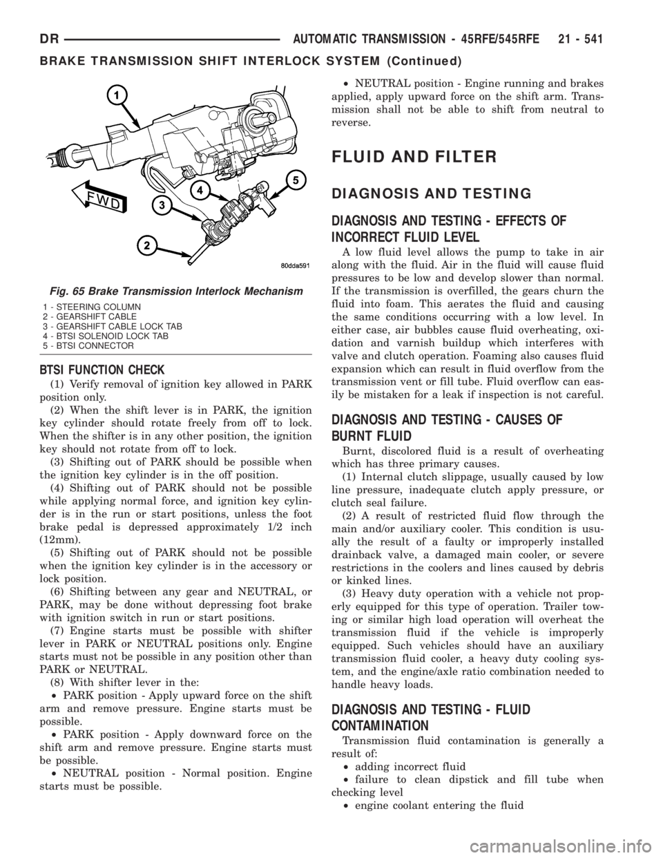
Fig. 65 Brake Transmission Interlock Mechanism
1 - STEERING COLUMN
2 - GEARSHIFT CABLE
3 - GEARSHIFT CABLE LOCK TAB
4 - BTSI SOLENOID LOCK TAB
5 - BTSI CONNECTOR
DRAUTOMATIC TRANSMISSION - 45RFE/545RFE 21 - 541
BRAKE TRANSMISSION SHIFT INTERLOCK SYSTEM (Continued)
Page 2384 of 2895
(4) Lower the vehicle.
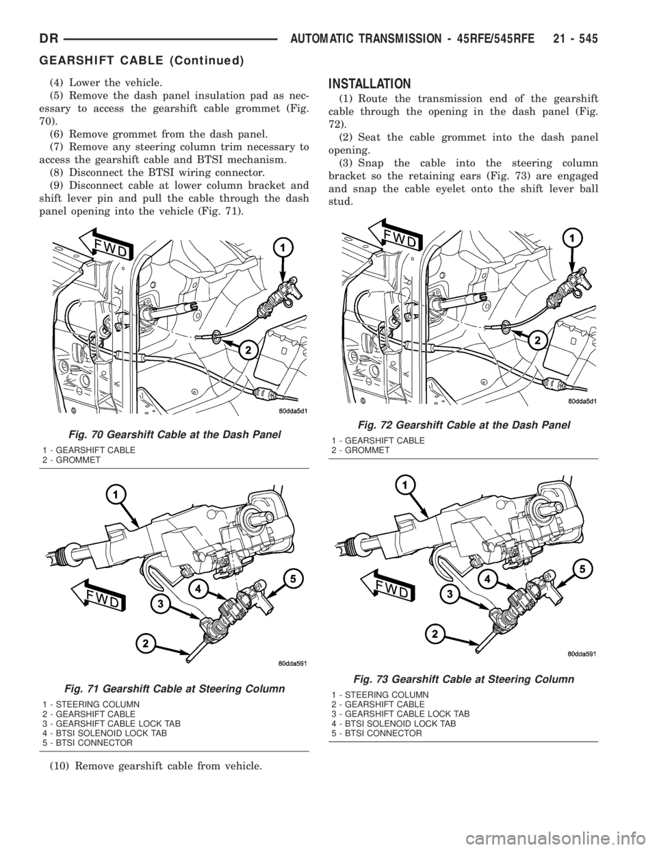
(5) Remove the dash panel insulation pad as nec-
essary to access the gearshift cable grommet (Fig.
70).
(6) Remove grommet from the dash panel.
(7) Remove any steering column trim necessary to
access the gearshift cable and BTSI mechanism.
(8) Disconnect the BTSI wiring connector.
(9) Disconnect cable at lower column bracket and
shift lever pin and pull the cable through the dash
panel opening into the vehicle (Fig. 71).
(10) Remove gearshift cable from vehicle.INSTALLATION
(1) Route the transmission end of the gearshift
cable through the opening in the dash panel (Fig.
72).
(2) Seat the cable grommet into the dash panel
opening.
(3) Snap the cable into the steering column
bracket so the retaining ears (Fig. 73) are engaged
and snap the cable eyelet onto the shift lever ball
stud.
Fig. 70 Gearshift Cable at the Dash Panel
1 - GEARSHIFT CABLE
2 - GROMMET
Fig. 71 Gearshift Cable at Steering Column
1 - STEERING COLUMN
2 - GEARSHIFT CABLE
3 - GEARSHIFT CABLE LOCK TAB
4 - BTSI SOLENOID LOCK TAB
5 - BTSI CONNECTOR
Fig. 72 Gearshift Cable at the Dash Panel
1 - GEARSHIFT CABLE
2 - GROMMET
Fig. 73 Gearshift Cable at Steering Column
1 - STEERING COLUMN
2 - GEARSHIFT CABLE
3 - GEARSHIFT CABLE LOCK TAB
4 - BTSI SOLENOID LOCK TAB
5 - BTSI CONNECTOR
DRAUTOMATIC TRANSMISSION - 45RFE/545RFE 21 - 545
GEARSHIFT CABLE (Continued)
Page 2385 of 2895
(4) Raise the vehicle.
(5) Place the transmission manual shift lever in
the ªPARKº detent (rearmost) position and rotate
prop shaft to ensure transmission is in PARK.
(6) Route the gearshift cable through the transmis-
sion mounting bracket and secure the cable by snap-
ping the cable retaining ears into the transmission
bracket and snapping the cable eyelet on the manual
shift lever ball stud.
(7) Lower vehicle.
(8) Lock the shift cable adjustment by pressing the
cable adjuster lock tab downward until it snaps into
place.
(9) Check for proper operation of the transmission
range sensor.
(10) Adjust the gearshift cable and BTSI mecha-
nism as necessary.
ADJUSTMENTS
GEARSHIFT CABLE
Check adjustment by starting the engine in PARK
and NEUTRAL. Adjustment is CORRECT if the
engine starts only in these positions. Adjustment is
INCORRECT if the engine starts in one but not both
positions. If the engine starts in any position other
than PARK or NEUTRAL, or if the engine will not
start at all, the transmission range sensor may be
faulty.
Gearshift Adjustment Procedure
(1) Shift transmission into PARK.
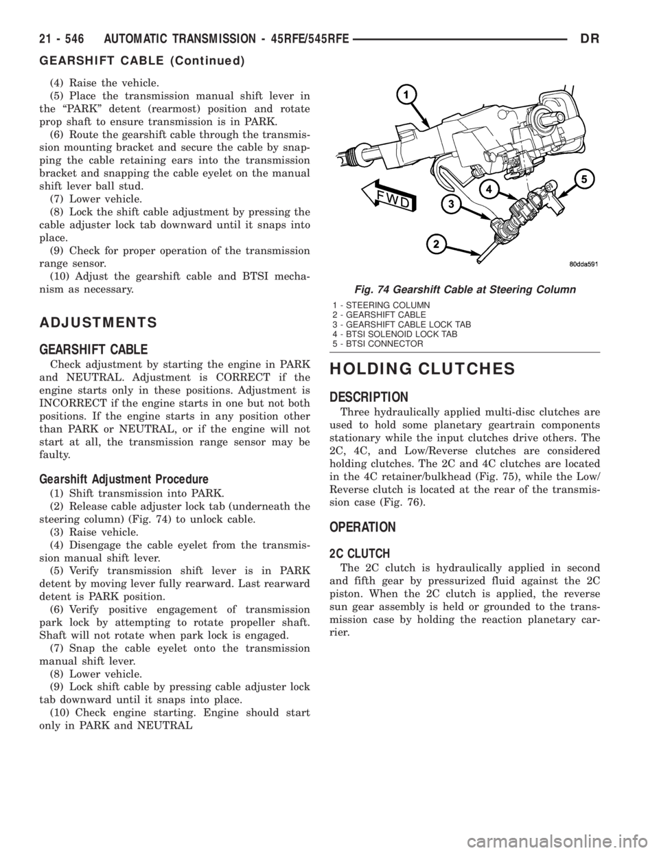
(2) Release cable adjuster lock tab (underneath the
steering column) (Fig. 74) to unlock cable.
(3) Raise vehicle.
(4) Disengage the cable eyelet from the transmis-
sion manual shift lever.
(5) Verify transmission shift lever is in PARK
detent by moving lever fully rearward. Last rearward
detent is PARK position.
(6) Verify positive engagement of transmission
park lock by attempting to rotate propeller shaft.
Shaft will not rotate when park lock is engaged.
(7) Snap the cable eyelet onto the transmission
manual shift lever.
(8) Lower vehicle.
(9) Lock shift cable by pressing cable adjuster lock
tab downward until it snaps into place.
(10) Check engine starting. Engine should start
only in PARK and NEUTRAL
HOLDING CLUTCHES
DESCRIPTION
Three hydraulically applied multi-disc clutches are
used to hold some planetary geartrain components
stationary while the input clutches drive others. The
2C, 4C, and Low/Reverse clutches are considered
holding clutches. The 2C and 4C clutches are located
in the 4C retainer/bulkhead (Fig. 75), while the Low/
Reverse clutch is located at the rear of the transmis-
sion case (Fig. 76).
OPERATION
2C CLUTCH
The 2C clutch is hydraulically applied in second
and fifth gear by pressurized fluid against the 2C
piston. When the 2C clutch is applied, the reverse
sun gear assembly is held or grounded to the trans-
mission case by holding the reaction planetary car-
rier.
Fig. 74 Gearshift Cable at Steering Column
1 - STEERING COLUMN
2 - GEARSHIFT CABLE
3 - GEARSHIFT CABLE LOCK TAB
4 - BTSI SOLENOID LOCK TAB
5 - BTSI CONNECTOR
21 - 546 AUTOMATIC TRANSMISSION - 45RFE/545RFEDR
GEARSHIFT CABLE (Continued)
Page 2398 of 2895
REMOVAL
(1) Raise vehicle.
(2) Place a suitable fluid catch pan under the
transmission.
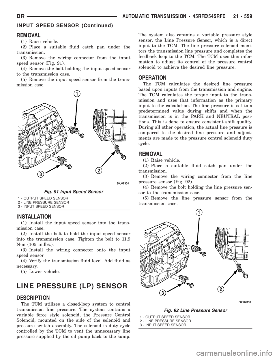
(3) Remove the wiring connector from the input
speed sensor (Fig. 91).
(4) Remove the bolt holding the input speed sensor
to the transmission case.
(5) Remove the input speed sensor from the trans-
mission case.
INSTALLATION
(1) Install the input speed sensor into the trans-
mission case.
(2) Install the bolt to hold the input speed sensor
into the transmission case. Tighten the bolt to 11.9
N´m (105 in.lbs.).
(3) Install the wiring connector onto the input
speed sensor
(4) Verify the transmission fluid level. Add fluid as
necessary.
(5) Lower vehicle.
LINE PRESSURE (LP) SENSOR
DESCRIPTION
The TCM utilizes a closed-loop system to control
transmission line pressure. The system contains a
variable force style solenoid, the Pressure Control
Solenoid, mounted on the side of the solenoid and
pressure switch assembly. The solenoid is duty cycle
controlled by the TCM to vent the unnecessary line
pressure supplied by the oil pump back to the sump.The system also contains a variable pressure style
sensor, the Line Pressure Sensor, which is a direct
input to the TCM. The line pressure solenoid moni-
tors the transmission line pressure and completes the
feedback loop to the TCM. The TCM uses this infor-
mation to adjust its control of the pressure control
solenoid to achieve the desired line pressure.
OPERATION
The TCM calculates the desired line pressure
based upon inputs from the transmission and engine.
The TCM calculates the torque input to the trans-
mission and uses that information as the primary
input to the calculation. The line pressure is set to a
predetermined value during shifts and when the
transmission is in the PARK and NEUTRAL posi-
tions. This is done to ensure consistent shift quality.
During all other operation, the actual line pressure is
compared to the desired line pressure and adjust-
ments are made to the pressure control solenoid duty
cycle.
REMOVAL
(1) Raise vehicle.
(2) Place a suitable fluid catch pan under the
transmission.
(3) Remove the wiring connector from the line
pressure sensor (Fig. 92).
(4) Remove the bolt holding the line pressure sen-
sor to the transmission case.
(5) Remove the line pressure sensor from the
transmission case.
Fig. 91 Input Speed Sensor
1 - OUTPUT SPEED SENSOR
2 - LINE PRESSURE SENSOR
3 - INPUT SPEED SENSOR
Fig. 92 Line Pressure Sensor
1 - OUTPUT SPEED SENSOR
2 - LINE PRESSURE SENSOR
3 - INPUT SPEED SENSOR
DRAUTOMATIC TRANSMISSION - 45RFE/545RFE 21 - 559
INPUT SPEED SENSOR (Continued)
Page 2399 of 2895
INSTALLATION
(1) Install the line pressure sensor into the trans-
mission case.
(2) Install the bolt to hold the line pressure sensor
into the transmission case. Tighten the bolt to 11.9
N´m (105 in.lbs.).
(3) Install the wiring connector onto the line pres-
sure sensor
(4) Verify the transmission fluid level. Add fluid as
necessary.
(5) Lower vehicle.
LOW/REVERSE CLUTCH
DISASSEMBLY
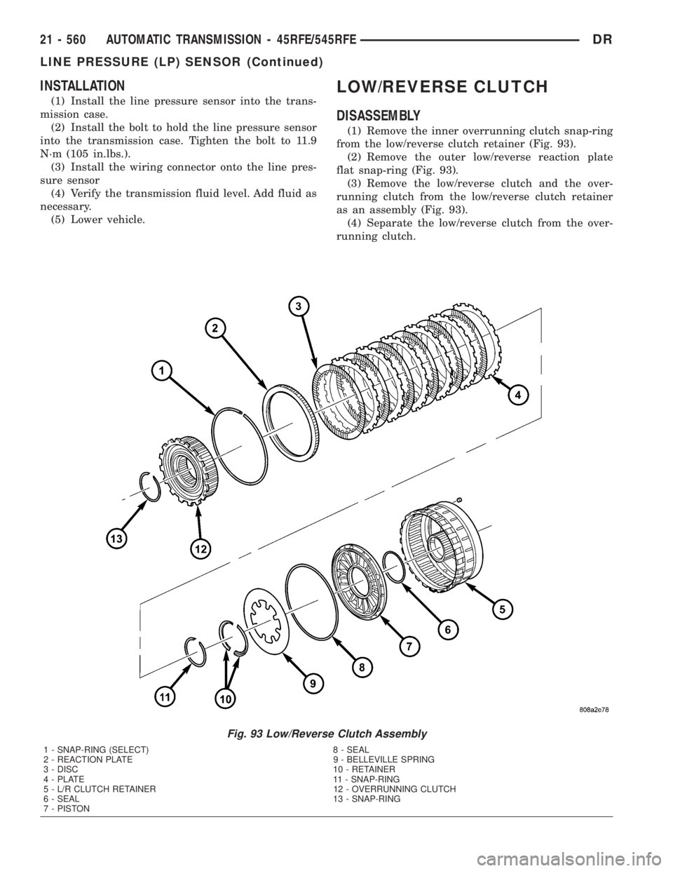
(1) Remove the inner overrunning clutch snap-ring
from the low/reverse clutch retainer (Fig. 93).
(2) Remove the outer low/reverse reaction plate
flat snap-ring (Fig. 93).
(3) Remove the low/reverse clutch and the over-
running clutch from the low/reverse clutch retainer
as an assembly (Fig. 93).
(4) Separate the low/reverse clutch from the over-
running clutch.
Fig. 93 Low/Reverse Clutch Assembly
1 - SNAP-RING (SELECT) 8 - SEAL
2 - REACTION PLATE 9 - BELLEVILLE SPRING
3 - DISC 10 - RETAINER
4 - PLATE 11 - SNAP-RING
5 - L/R CLUTCH RETAINER 12 - OVERRUNNING CLUTCH
6 - SEAL 13 - SNAP-RING
7 - PISTON
21 - 560 AUTOMATIC TRANSMISSION - 45RFE/545RFEDR
LINE PRESSURE (LP) SENSOR (Continued)
Page 2406 of 2895
into the appropriate oil pump valve body bore (Fig.
102) (Fig. 103).
(4) Place the separator plate onto the oil pump
body (Fig. 101).
(5) Install the screws to hold the separator plate
onto the oil pump body (Fig. 101). Tighten the screws
to 4.5 N´m (40 in.lbs.).
(6) Position the oil pump cover onto the locating
dowels (Fig. 100).
(7) Seat the two oil pump halves together and
install all bolts finger tight.
(8) Torque all bolts down slowly starting in the
center and working outward. The correct torque is
4.5 N´m (40 in.lbs.).
(9) Verify that the oil pump gears rotate freely and
smoothly.
(10) Position the reaction shaft support into the oil
pump (Fig. 100).
(11) Install and torque the bolts to hold the reac-
tion shaft support to the oil pump (Fig. 100). The cor-
rect torque is 12 N´m (105 in.lbs.).
OIL PUMP FRONT SEAL
REMOVAL
(1) Remove transmission from the vehicle.
(2) Remove the torque converter from the trans-
mission.
(3) Using a screw mounted in a slide hammer,
remove the oil pump front seal.
INSTALLATION
(1) Clean seal bore of the oil pump of any residue
or particles from the original seal.
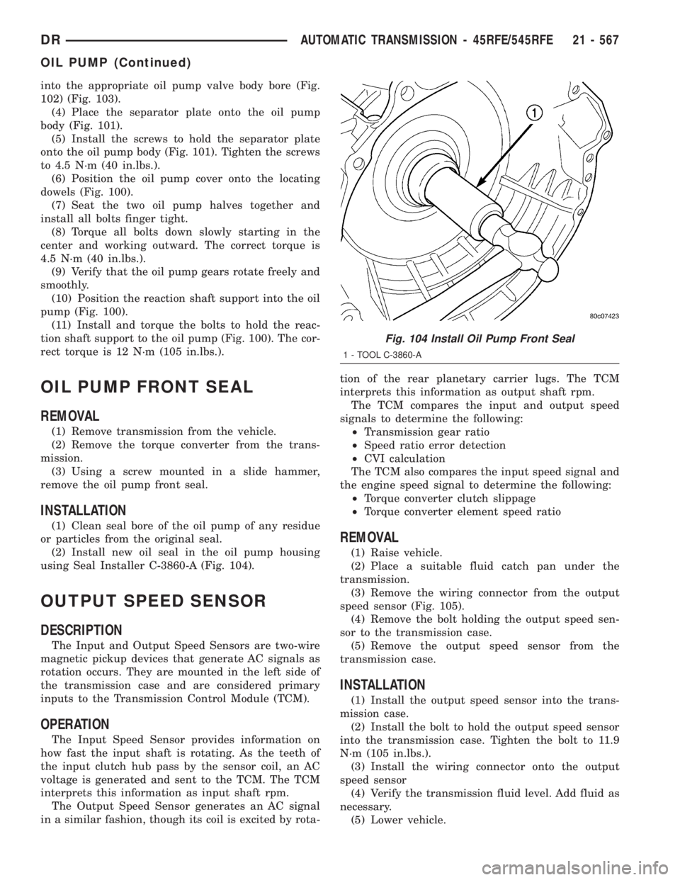
(2) Install new oil seal in the oil pump housing
using Seal Installer C-3860-A (Fig. 104).
OUTPUT SPEED SENSOR
DESCRIPTION
The Input and Output Speed Sensors are two-wire
magnetic pickup devices that generate AC signals as
rotation occurs. They are mounted in the left side of
the transmission case and are considered primary
inputs to the Transmission Control Module (TCM).
OPERATION
The Input Speed Sensor provides information on
how fast the input shaft is rotating. As the teeth of
the input clutch hub pass by the sensor coil, an AC
voltage is generated and sent to the TCM. The TCM
interprets this information as input shaft rpm.
The Output Speed Sensor generates an AC signal
in a similar fashion, though its coil is excited by rota-tion of the rear planetary carrier lugs. The TCM
interprets this information as output shaft rpm.
The TCM compares the input and output speed
signals to determine the following:
²Transmission gear ratio
²Speed ratio error detection
²CVI calculation
The TCM also compares the input speed signal and
the engine speed signal to determine the following:
²Torque converter clutch slippage
²Torque converter element speed ratio
REMOVAL
(1) Raise vehicle.
(2) Place a suitable fluid catch pan under the
transmission.
(3) Remove the wiring connector from the output
speed sensor (Fig. 105).
(4) Remove the bolt holding the output speed sen-
sor to the transmission case.
(5) Remove the output speed sensor from the
transmission case.
INSTALLATION
(1) Install the output speed sensor into the trans-
mission case.
(2) Install the bolt to hold the output speed sensor
into the transmission case. Tighten the bolt to 11.9
N´m (105 in.lbs.).
(3) Install the wiring connector onto the output
speed sensor
(4) Verify the transmission fluid level. Add fluid as
necessary.
(5) Lower vehicle.
Fig. 104 Install Oil Pump Front Seal
1 - TOOL C-3860-A
DRAUTOMATIC TRANSMISSION - 45RFE/545RFE 21 - 567
OIL PUMP (Continued)
Page 2407 of 2895
OVERDRIVE SWITCH
DESCRIPTION
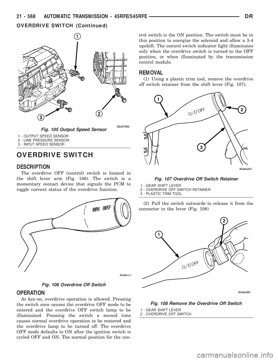
The overdrive OFF (control) switch is located in
the shift lever arm (Fig. 106). The switch is a
momentary contact device that signals the PCM to
toggle current status of the overdrive function.
OPERATION
At key-on, overdrive operation is allowed. Pressing
the switch once causes the overdrive OFF mode to be
entered and the overdrive OFF switch lamp to be
illuminated. Pressing the switch a second time
causes normal overdrive operation to be restored and
the overdrive lamp to be turned off. The overdrive
OFF mode defaults to ON after the ignition switch is
cycled OFF and ON. The normal position for the con-trol switch is the ON position. The switch must be in
this position to energize the solenoid and allow a 3-4
upshift. The control switch indicator light illuminates
only when the overdrive switch is turned to the OFF
position, or when illuminated by the transmission
control module.
REMOVAL
(1) Using a plastic trim tool, remove the overdrive
off switch retainer from the shift lever (Fig. 107).
(2) Pull the switch outwards to release it from the
connector in the lever (Fig. 108)
Fig. 105 Output Speed Sensor
1 - OUTPUT SPEED SENSOR
2 - LINE PRESSURE SENSOR
3 - INPUT SPEED SENSOR
Fig. 106 Overdrive Off Switch
Fig. 107 Overdrive Off Switch Retainer
1 - GEAR SHIFT LEVER
2 - OVERDRIVE OFF SWITCH RETAINER
3 - PLASTIC TRIM TOOL
Fig. 108 Remove the Overdrive Off Switch
1 - GEAR SHIFT LEVER
2 - OVERDRIVE OFF SWITCH
21 - 568 AUTOMATIC TRANSMISSION - 45RFE/545RFEDR
OVERDRIVE SWITCH (Continued)
Page 2408 of 2895
INSTALLATION
NOTE: There is enough slack in the wire to pull out
the connector from the lever.
(1) Pull the connector out of the lever just enough
to grasp it.
CAUTION: Be careful not to bend the pins on the
overdrive off switch. Use care when installing the
switch, as it is not indexed, and can be accidentally
installed incorrectly.
(2) Install the overdrive off switch into the connec-
tor (Fig. 109)
(3) Push the overdrive off switch and wiring into
the shift lever.
(4) Install the overdrive off switch retainer onto
the shift lever.
PISTONS
DESCRIPTION
There are several sizes and types of pistons used in
an automatic transmission. Some pistons are used to
apply clutches, while others are used to apply bands.
They all have in common the fact that they are round or
circular in shape, located within a smooth walled cylin-
der, which is closed at one end and converts fluid pres-
sure into mechanical movement. The fluid pressure
exerted on the piston is contained within the system
through the use of piston rings or seals.
OPERATION
The principal which makes this operation possible
is known as Pascal's Law. Pascal's Law can be statedas: ªPressure on a confined fluid is transmitted
equally in all directions and acts with equal force on
equal areas.º
PRESSURE
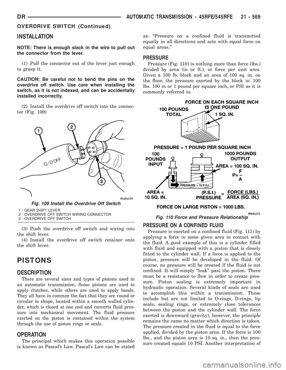
Pressure (Fig. 110) is nothing more than force (lbs.)
divided by area (in or ft.), or force per unit area.
Given a 100 lb. block and an area of 100 sq. in. on
the floor, the pressure exerted by the block is: 100
lbs. 100 in or 1 pound per square inch, or PSI as it is
commonly referred to.
PRESSURE ON A CONFINED FLUID
Pressure is exerted on a confined fluid (Fig. 111) by
applying a force to some given area in contact with
the fluid. A good example of this is a cylinder filled
with fluid and equipped with a piston that is closely
fitted to the cylinder wall. If a force is applied to the
piston, pressure will be developed in the fluid. Of
course, no pressure will be created if the fluid is not
confined. It will simply ªleakº past the piston. There
must be a resistance to flow in order to create pres-
sure. Piston sealing is extremely important in
hydraulic operation. Several kinds of seals are used
to accomplish this within a transmission. These
include but are not limited to O-rings, D-rings, lip
seals, sealing rings, or extremely close tolerances
between the piston and the cylinder wall. The force
exerted is downward (gravity), however, the principle
remains the same no matter which direction is taken.
The pressure created in the fluid is equal to the force
applied, divided by the piston area. If the force is 100
lbs., and the piston area is 10 sq. in., then the pres-
sure created equals 10 PSI. Another interpretation of
Fig. 109 Install the Overdrive Off Switch
1 - GEAR SHIFT LEVER
2 - OVERDRIVE OFF SWITCH WIRING CONNECTOR
3 - OVERDRIVE OFF SWITCH
Fig. 110 Force and Pressure Relationship
DRAUTOMATIC TRANSMISSION - 45RFE/545RFE 21 - 569
OVERDRIVE SWITCH (Continued)