2003 DODGE RAM C1 connector
[x] Cancel search: C1 connectorPage 2603 of 2895
DOORS - REAR
TABLE OF CONTENTS
page page
DOOR
REMOVAL.............................28
INSTALLATION.........................28
ADJUSTMENTS
ADJUSTMENT........................28
DOOR GLASS
REMOVAL.............................30
INSTALLATION.........................30
EXTERIOR HANDLE
REMOVAL.............................30
INSTALLATION.........................30
GLASS RUN CHANNEL
REMOVAL.............................30
INSTALLATION.........................31
HINGE
REMOVAL.............................31
INSTALLATION.........................31
INSIDE HANDLE ACTUATOR
REMOVAL.............................31
INSTALLATION.........................32
LATCH
REMOVAL.............................32INSTALLATION.........................32
ADJUSTMENTS
ADJUSTMENT........................32
LATCH STRIKER
REMOVAL.............................33
INSTALLATION.........................33
ADJUSTMENTS
ADJUSTMENT........................33
TRIM PANEL
REMOVAL.............................33
INSTALLATION.........................33
WATERDAM
REMOVAL.............................34
INSTALLATION.........................34
WINDOW REGULATOR - POWER
REMOVAL.............................34
INSTALLATION.........................34
WINDOW REGULATOR - MANUAL
REMOVAL.............................35
INSTALLATION.........................35
DOOR
REMOVAL
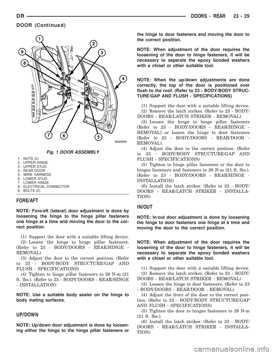
(1) Disconnect the door wire harness electrical con-
nector at the b-pillar. (Fig. 1)
(2) Using a grease pencil or equivalent, mark the
outline of the door hinges on the door to aid in instal-
lation.
(3) Support the door with a suitable lifting device.
NOTE: The epoxy bonded washers should not be
seperated from the hinge. If the washers are
removed the door may have to be re-adjusted.
(4) Remove the nuts and bolts attaching the door
hinges to the door.
INSTALLATION
(1) Support the door with a suitable lifting device
and install the door onto the hinges.
(2) Install the bolts, nuts and washers, if there
were removed previously, and tighten to 28 N´m (21
ft. lbs.).(3) Connect the electrical connector.
(4) Adjust the door as necessary. (Refer to 23 -
BODY/DOORS - REAR/DOOR - ADJUSTMENTS)
ADJUSTMENTS
ADJUSTMENT
NOTE: For vehicles equipped with four doors, it is
recommended that you adjust the rear door before
adjusting the front door.
²Door adjustment measurements should be
taken from stationary or welded body panels like
the roof, rocker or quarter panels.
²During adjustment procedures, it is recom-
mended that all the hinge fasteners be loosened
except for the upper most fasteners. Adjustments
can be made using the upper fasteners to hold the
door with final torque of the fasteners occurring
after correct door positioning is achieved.
23 - 28 DOORS - REARDR
Page 2604 of 2895
FORE/AFT
NOTE: Fore/aft (lateral) door adjustment is done by
loosening the hinge to the hinge pillar fasteners
one hinge at a time and moving the door to the cor-
rect position.
(1) Support the door with a suitable lifting device.
(2) Loosen the hinge to hinge pillar fasteners.
(Refer to 23 - BODY/DOORS - REAR/HINGE -
REMOVAL)
(3) Adjust the door to the correct position. (Refer
to 23 - BODY/BODY STRUCTURE/GAP AND
FLUSH - SPECIFICATIONS)
(4) Tighten to hinge pillar fasteners to 28 N´m (21
ft. lbs.). (Refer to 23 - BODY/DOORS - REAR/HINGE
- INSTALLATION)
NOTE: Use a suitable body sealer on the hinge to
body mating surfaces.
UP/DOWN
NOTE: Up/down door adjustment is done by loosen-
ing either the hinge to the hinge pillar fasteners orthe hinge to door fasteners and moving the door to
the correct position.
NOTE: When adjustment of the door requires the
loosening of the door to hinge fasteners, it will be
necessary to separate the epoxy bonded washers
with a chisel or other suitable tool.
NOTE: When the up/down adjustments are done
correctly, the top of the door is positioned over
flush to the roof. (Refer to 23 - BODY/BODY STRUC-
TURE/GAP AND FLUSH - SPECIFICATIONS)
(1) Support the door with a suitable lifting device.
(2) Remove the latch striker. (Refer to 23 - BODY/
DOORS - REAR/LATCH STRIKER - REMOVAL)
(3) Loosen the hinge to hinge pillar fasteners
(Refer to 23 - BODY/DOORS - REAR/HINGE -
REMOVAL) or loosen the hinge to door fasteners
(Refer to 23 - BODY/DOORS - REAR/DOOR -
REMOVAL).
(4) Adjust the door to the correct position. (Refer
to 23 - BODY/BODY STRUCTURE/GAP AND
FLUSH - SPECIFICATIONS)
(5) Tighten to hinge pillar fasteners or the door to
hinges fasteners and fasteners to 28 N´m (21 ft. lbs.).
(Refer to 23 - BODY/DOORS - REAR/HINGE -
INSTALLATION)
(6) Install the latch striker. (Refer to 23 - BODY/
DOORS - REAR/LATCH STRIKER - INSTALLA-
TION)
IN/OUT
NOTE: In/out door adjustment is done by loosening
the hinge to door fasteners one hinge at a time and
moving the door to the correct position.
NOTE: When adjustment of the door requires the
loosening of the door to hinge fasteners, it will be
necessary to separate the epoxy bonded washers
with a chisel or other suitable tool.
(1) Support the door with a suitable lifting device.
(2) Remove the latch striker. (Refer to 23 - BODY/
DOORS - REAR/LATCH STRIKER - REMOVAL)
(3) Loosen the hinge to door fasteners. (Refer to 23
- BODY/DOORS - REAR/DOOR - REMOVAL)
(4) Adjust the front of the door to the correct posi-
tion. (Refer to 23 - BODY/BODY STRUCTURE/GAP
AND FLUSH - SPECIFICATIONS)
(5) Tighten the door to hinges fasteners to 28 N´m
(21 ft. lbs.).
(6) Install the latch striker. (Refer to 23 - BODY/
DOORS - REAR/LATCH STRIKER - INSTALLA-
TION)
Fig. 1 DOOR ASSEMBLY
1 - NUTS (2)
2 - UPPER HINGE
3 - UPPER STUD
4 - REAR DOOR
5 - WIRE HARNESS
6 - LOWER STUD
7 - LOWER HINGE
8 - ELECTRICAL CONNECTOR
9 - BOLTS (2)
DRDOORS - REAR 23 - 29
DOOR (Continued)
Page 2607 of 2895
INSTALLATION
(1) Install the remote handle actuator and install
the nuts.
(2) Tighten the nuts to 10 N´m (89 in. lbs.).
(3) Connect the latch actuator rod.
(4) Install the door trim panel. (Refer to 23 -
BODY/DOORS - REAR/TRIM PANEL - INSTALLA-
TION)
(5) Install the inside handle and install the bolt.
(6) Tighten the bolt to 9 N´m (80 in. lbs.).
LATCH
REMOVAL
(1) Raise the window to the full up position.
(2) Remove the waterdam. (Refer to 23 - BODY/
DOOR - FRONT/WATERDAM - REMOVAL)
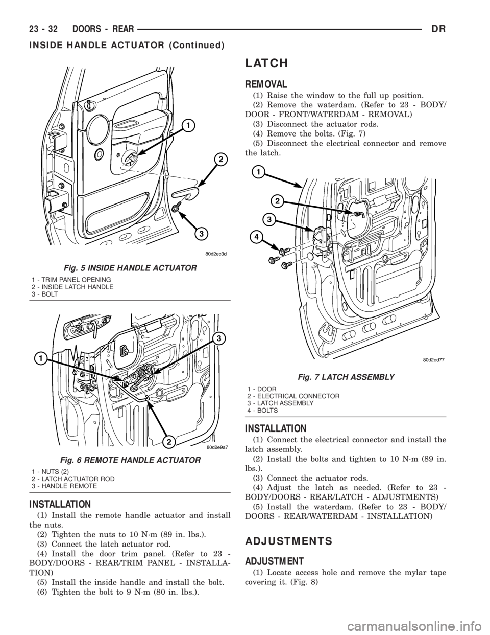
(3) Disconnect the actuator rods.
(4) Remove the bolts. (Fig. 7)
(5) Disconnect the electrical connector and remove
the latch.
INSTALLATION
(1) Connect the electrical connector and install the
latch assembly.
(2) Install the bolts and tighten to 10 N´m (89 in.
lbs.).
(3) Connect the actuator rods.
(4) Adjust the latch as needed. (Refer to 23 -
BODY/DOORS - REAR/LATCH - ADJUSTMENTS)
(5) Install the waterdam. (Refer to 23 - BODY/
DOORS - REAR/WATERDAM - INSTALLATION)
ADJUSTMENTS
ADJUSTMENT
(1) Locate access hole and remove the mylar tape
covering it. (Fig. 8)
Fig. 5 INSIDE HANDLE ACTUATOR
1 - TRIM PANEL OPENING
2 - INSIDE LATCH HANDLE
3 - BOLT
Fig. 6 REMOTE HANDLE ACTUATOR
1 - NUTS (2)
2 - LATCH ACTUATOR ROD
3 - HANDLE REMOTE
Fig. 7 LATCH ASSEMBLY
1 - DOOR
2 - ELECTRICAL CONNECTOR
3 - LATCH ASSEMBLY
4 - BOLTS
23 - 32 DOORS - REARDR
INSIDE HANDLE ACTUATOR (Continued)
Page 2608 of 2895
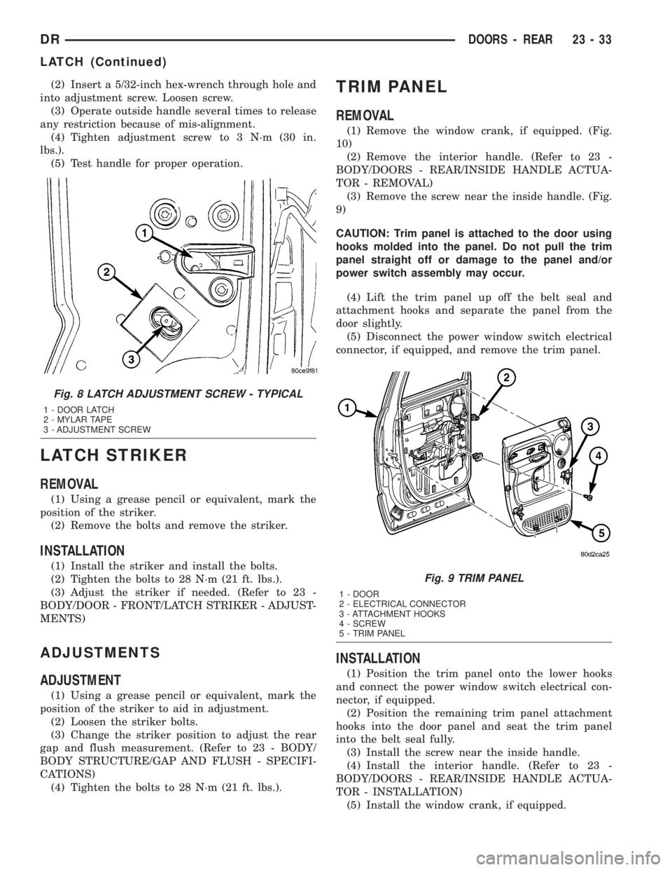
(2) Insert a 5/32-inch hex-wrench through hole and
into adjustment screw. Loosen screw.
(3) Operate outside handle several times to release
any restriction because of mis-alignment.
(4) Tighten adjustment screw to 3 N´m (30 in.
lbs.).
(5) Test handle for proper operation.
LATCH STRIKER
REMOVAL
(1) Using a grease pencil or equivalent, mark the
position of the striker.
(2) Remove the bolts and remove the striker.
INSTALLATION
(1) Install the striker and install the bolts.
(2) Tighten the bolts to 28 N´m (21 ft. lbs.).
(3) Adjust the striker if needed. (Refer to 23 -
BODY/DOOR - FRONT/LATCH STRIKER - ADJUST-
MENTS)
ADJUSTMENTS
ADJUSTMENT
(1) Using a grease pencil or equivalent, mark the
position of the striker to aid in adjustment.
(2) Loosen the striker bolts.
(3) Change the striker position to adjust the rear
gap and flush measurement. (Refer to 23 - BODY/
BODY STRUCTURE/GAP AND FLUSH - SPECIFI-
CATIONS)
(4) Tighten the bolts to 28 N´m (21 ft. lbs.).
TRIM PANEL
REMOVAL
(1) Remove the window crank, if equipped. (Fig.
10)
(2) Remove the interior handle. (Refer to 23 -
BODY/DOORS - REAR/INSIDE HANDLE ACTUA-
TOR - REMOVAL)
(3) Remove the screw near the inside handle. (Fig.
9)
CAUTION: Trim panel is attached to the door using
hooks molded into the panel. Do not pull the trim
panel straight off or damage to the panel and/or
power switch assembly may occur.
(4) Lift the trim panel up off the belt seal and
attachment hooks and separate the panel from the
door slightly.
(5) Disconnect the power window switch electrical
connector, if equipped, and remove the trim panel.
INSTALLATION
(1) Position the trim panel onto the lower hooks
and connect the power window switch electrical con-
nector, if equipped.
(2) Position the remaining trim panel attachment
hooks into the door panel and seat the trim panel
into the belt seal fully.
(3) Install the screw near the inside handle.
(4) Install the interior handle. (Refer to 23 -
BODY/DOORS - REAR/INSIDE HANDLE ACTUA-
TOR - INSTALLATION)
(5) Install the window crank, if equipped.
Fig. 8 LATCH ADJUSTMENT SCREW - TYPICAL
1 - DOOR LATCH
2 - MYLAR TAPE
3 - ADJUSTMENT SCREW
Fig. 9 TRIM PANEL
1 - DOOR
2 - ELECTRICAL CONNECTOR
3 - ATTACHMENT HOOKS
4 - SCREW
5 - TRIM PANEL
DRDOORS - REAR 23 - 33
LATCH (Continued)
Page 2609 of 2895
WATERDAM
REMOVAL
(1) Remove the inside handle actuator. (Refer to 23
- BODY/DOORS - REAR/INSIDE HANDLE ACTUA-
TOR - REMOVAL)
(2) Remove the speaker. (Refer to 8 - ELECTRI-
CAL/AUDIO/SPEAKER - REMOVAL)
(3) Separate the waterdam from the inner door
panel and off of the latch linkages.
INSTALLATION
(1) Position the wire harness and actuator rods
through the holes in the waterdam.
(2) Secure the waterdam to the inner door panel.
(3) Install the speaker. (Refer to 8 - ELECTRICAL/
AUDIO/SPEAKER - INSTALLATION)
(4) Install the inside handle actuator. (Refer to 23 -
BODY/DOORS - REAR/INSIDE HANDLE ACTUA-
TOR - INSTALLATION)
WINDOW REGULATOR -
POWER
REMOVAL
(1) Remove the waterdam. (Refer to 23 - BODY/
DOORS - REAR/WATERDAM - REMOVAL)
(2) Remove the window switch from the door trim
panel and reconnect it to the door wire harness.
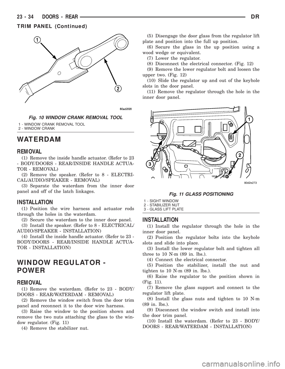
(3) Raise the window to the position shown and
remove the two nuts attaching the glass to the win-
dow regulator. (Fig. 11)
(4) Remove the stabilizer nut.(5) Disengage the door glass from the regulator lift
plate and position into the full up position.
(6) Secure the glass in the up position using a
wood wedge or equivalent.
(7) Lower the regulator.
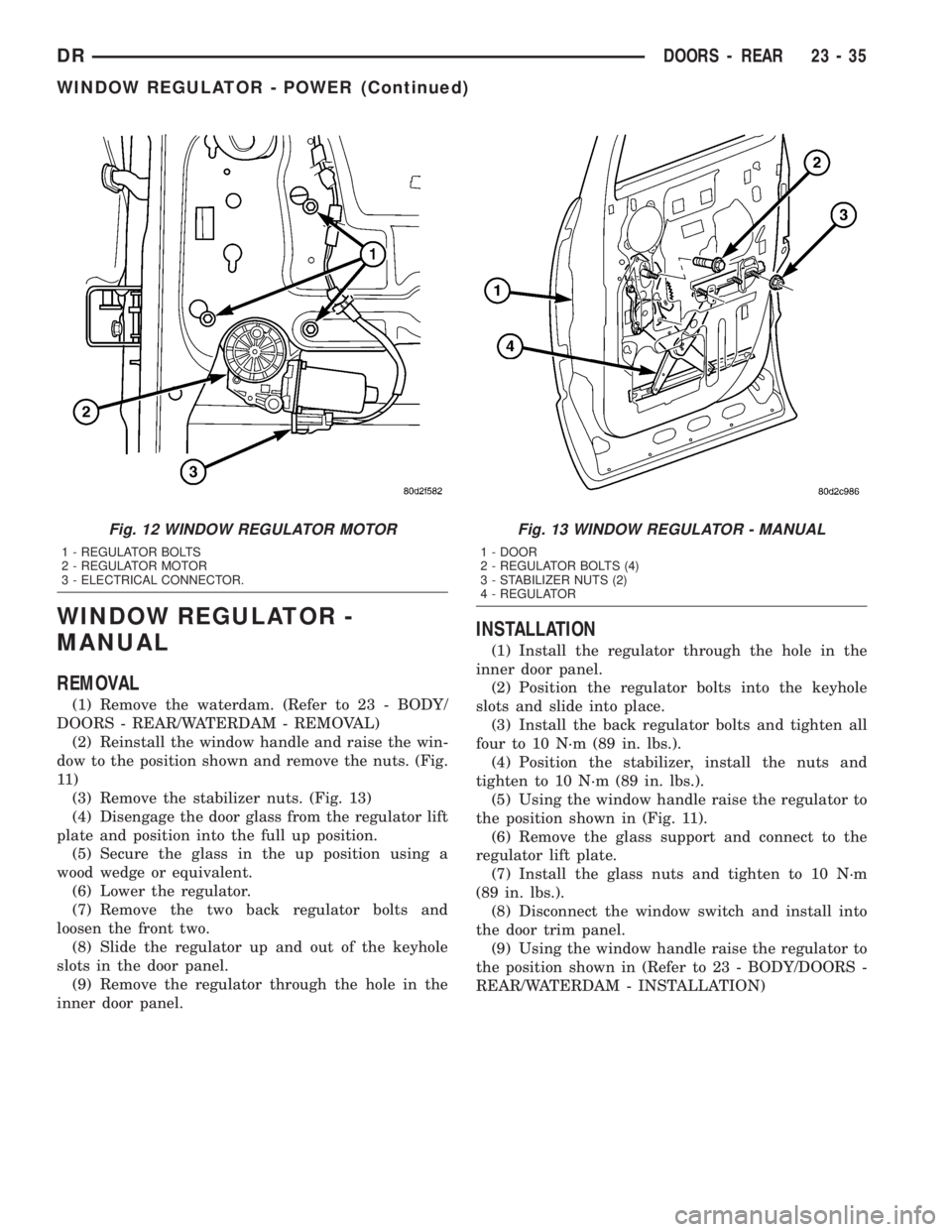
(8) Disconnect the electrical connector. (Fig. 12)
(9) Remove the lower regulator bolt and loosen the
upper two. (Fig. 12)
(10) Slide the regulator up and out of the keyhole
slots in the door panel.
(11) Remove the regulator through the hole in the
inner door panel.
INSTALLATION
(1) Install the regulator through the hole in the
inner door panel.
(2) Position the regulator bolts into the keyhole
slots and slide into place.
(3) Install the lower regulator bolt and tighten all
three to 10 N´m (89 in. lbs.).
(4) Connect the electrical connector.
(5) Position the stabilizer, install the nut and
tighten to 10 N´m (89 in. lbs.).
(6) Raise the regulator to the position shown in
(Fig. 11).
(7) Remove the glass support and connect to the
regulator lift plate.
(8) Install the glass nuts and tighten to 10 N´m
(89 in. lbs.).
(9) Disconnect the window switch and install into
the door trim panel.
(10) Install the waterdam. (Refer to 23 - BODY/
DOORS - REAR/WATERDAM - INSTALLATION)
Fig. 10 WINDOW CRANK REMOVAL TOOL
1 - WINDOW CRANK REMOVAL TOOL
2 - WINDOW CRANK
Fig. 11 GLASS POSITIONING
1 - SIGHT WINDOW
2 - STABILIZER NUT
3 - GLASS LIFT PLATE
23 - 34 DOORS - REARDR
TRIM PANEL (Continued)
Page 2610 of 2895
WINDOW REGULATOR -
MANUAL
REMOVAL
(1) Remove the waterdam. (Refer to 23 - BODY/
DOORS - REAR/WATERDAM - REMOVAL)
(2) Reinstall the window handle and raise the win-
dow to the position shown and remove the nuts. (Fig.
11 )
(3) Remove the stabilizer nuts. (Fig. 13)
(4) Disengage the door glass from the regulator lift
plate and position into the full up position.
(5) Secure the glass in the up position using a
wood wedge or equivalent.
(6) Lower the regulator.
(7) Remove the two back regulator bolts and
loosen the front two.
(8) Slide the regulator up and out of the keyhole
slots in the door panel.
(9) Remove the regulator through the hole in the
inner door panel.
INSTALLATION
(1) Install the regulator through the hole in the
inner door panel.
(2) Position the regulator bolts into the keyhole
slots and slide into place.
(3) Install the back regulator bolts and tighten all
four to 10 N´m (89 in. lbs.).
(4) Position the stabilizer, install the nuts and
tighten to 10 N´m (89 in. lbs.).
(5) Using the window handle raise the regulator to
the position shown in (Fig. 11).
(6) Remove the glass support and connect to the
regulator lift plate.
(7) Install the glass nuts and tighten to 10 N´m
(89 in. lbs.).
(8) Disconnect the window switch and install into
the door trim panel.
(9) Using the window handle raise the regulator to
the position shown in (Refer to 23 - BODY/DOORS -
REAR/WATERDAM - INSTALLATION)
Fig. 12 WINDOW REGULATOR MOTOR
1 - REGULATOR BOLTS
2 - REGULATOR MOTOR
3 - ELECTRICAL CONNECTOR.
Fig. 13 WINDOW REGULATOR - MANUAL
1 - DOOR
2 - REGULATOR BOLTS (4)
3 - STABILIZER NUTS (2)
4 - REGULATOR
DRDOORS - REAR 23 - 35
WINDOW REGULATOR - POWER (Continued)
Page 2615 of 2895
INSTALLATION
(1) Position the grille onto the grille frame.
(2) Install the six upper nuts.
(3) Install the six lower screws.
GRILLE FRAME
REMOVAL
(1) Remove the grille. (Refer to 23 - BODY/EXTE-
RIOR/GRILLE - REMOVAL)
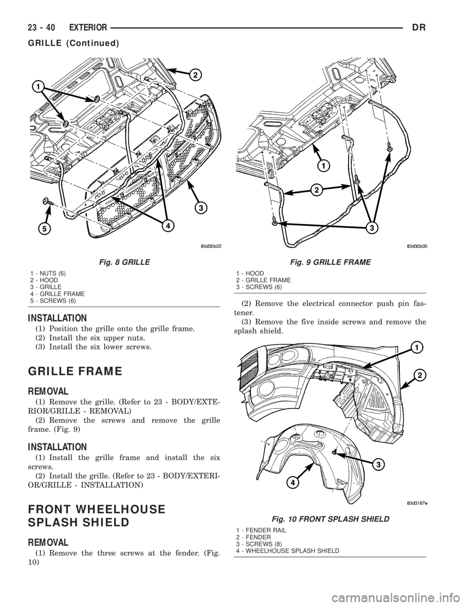
(2) Remove the screws and remove the grille
frame. (Fig. 9)
INSTALLATION
(1) Install the grille frame and install the six
screws.
(2) Install the grille. (Refer to 23 - BODY/EXTERI-
OR/GRILLE - INSTALLATION)
FRONT WHEELHOUSE
SPLASH SHIELD
REMOVAL
(1) Remove the three screws at the fender. (Fig.
10)(2) Remove the electrical connector push pin fas-
tener.
(3) Remove the five inside screws and remove the
splash shield.
Fig. 8 GRILLE
1 - NUTS (6)
2 - HOOD
3 - GRILLE
4 - GRILLE FRAME
5 - SCREWS (6)
Fig. 9 GRILLE FRAME
1 - HOOD
2 - GRILLE FRAME
3 - SCREWS (6)
Fig. 10 FRONT SPLASH SHIELD
1 - FENDER RAIL
2 - FENDER
3 - SCREWS (8)
4 - WHEELHOUSE SPLASH SHIELD
23 - 40 EXTERIORDR
GRILLE (Continued)
Page 2616 of 2895
INSTALLATION
(1) Install the splash shield and position the front
edge into the support bracket on the bumper.
(2) Install the five inner screws.
(3) Install the three screws at the fender.
(4) Install the electrical connector push pin fas-
tener.
REAR WHEELHOUSE SPLASH
SHIELD
REMOVAL
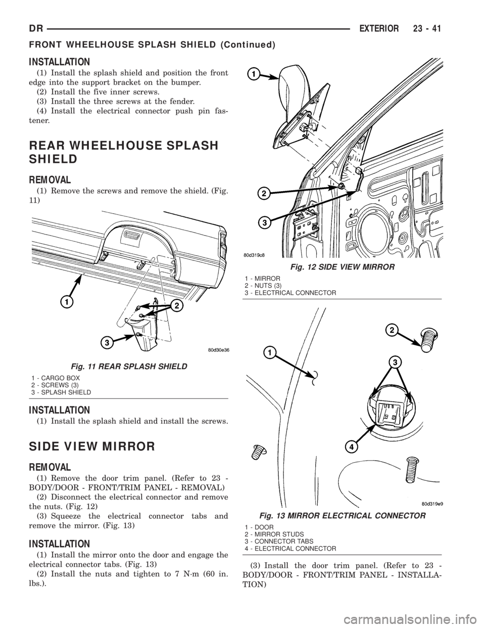
(1) Remove the screws and remove the shield. (Fig.
11 )
INSTALLATION
(1) Install the splash shield and install the screws.
SIDE VIEW MIRROR
REMOVAL
(1) Remove the door trim panel. (Refer to 23 -
BODY/DOOR - FRONT/TRIM PANEL - REMOVAL)
(2) Disconnect the electrical connector and remove
the nuts. (Fig. 12)
(3) Squeeze the electrical connector tabs and
remove the mirror. (Fig. 13)
INSTALLATION
(1) Install the mirror onto the door and engage the
electrical connector tabs. (Fig. 13)
(2) Install the nuts and tighten to 7 N´m (60 in.
lbs.).(3) Install the door trim panel. (Refer to 23 -
BODY/DOOR - FRONT/TRIM PANEL - INSTALLA-
TION)
Fig. 11 REAR SPLASH SHIELD
1 - CARGO BOX
2 - SCREWS (3)
3 - SPLASH SHIELD
Fig. 12 SIDE VIEW MIRROR
1 - MIRROR
2 - NUTS (3)
3 - ELECTRICAL CONNECTOR
Fig. 13 MIRROR ELECTRICAL CONNECTOR
1 - DOOR
2 - MIRROR STUDS
3 - CONNECTOR TABS
4 - ELECTRICAL CONNECTOR
DREXTERIOR 23 - 41
FRONT WHEELHOUSE SPLASH SHIELD (Continued)