2003 DODGE RAM C1 connector
[x] Cancel search: C1 connectorPage 2136 of 2895
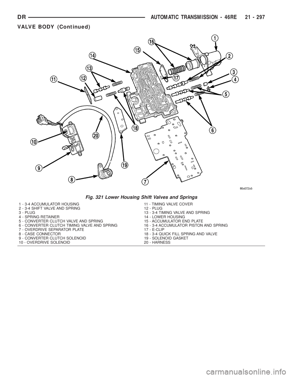
Fig. 321 Lower Housing Shift Valves and Springs
1 - 3-4 ACCUMULATOR HOUSING 11 - TIMING VALVE COVER
2 - 3-4 SHIFT VALVE AND SPRING 12 - PLUG
3 - PLUG 13 - 3-4 TIMING VALVE AND SPRING
4 - SPRING RETAINER 14 - LOWER HOUSING
5 - CONVERTER CLUTCH VALVE AND SPRING 15 - ACCUMULATOR END PLATE
6 - CONVERTER CLUTCH TIMING VALVE AND SPRING 16 - 3-4 ACCUMULATOR PISTON AND SPRING
7 - OVERDRIVE SEPARATOR PLATE 17 - E-CLIP
8 - CASE CONNECTOR 18 - 3-4 QUICK FILL SPRING AND VALVE
9 - CONVERTER CLUTCH SOLENOID 19 - SOLENOID GASKET
10 - OVERDRIVE SOLENOID 20 - HARNESS
DRAUTOMATIC TRANSMISSION - 46RE 21 - 297
VALVE BODY (Continued)
Page 2138 of 2895
Valve body bores do not change dimensionally with
use. If the valve body functioned correctly when new,
it will continue to operate properly after cleaning and
inspection. It should not be necessary to replace a
valve body assembly unless it is damaged in han-
dling.
The only serviceable valve body components are
listed below. The remaining valve body components
are serviced only as part of a complete valve body
assembly. Serviceable parts are:
²dual solenoid and harness assembly
²solenoid gasket
²solenoid case connector O-rings and shoulder
bolt
²switch valve and spring
²pressure adjusting screw and bracket assembly
²throttle lever
²manual lever and shaft seal
²throttle lever shaft seal, washer, and E-clip
²fluid filter and screws
²detent ball and spring
²valve body screws
²governor pressure solenoid
²governor pressure sensor and retaining clip
²park lock rod and E-clip
ASSEMBLY
CAUTION: Do not force valves or plugs into place
during reassembly. If the valve body bores, valves
and plugs are free of distortion or burrs, the valve
body components should all slide into place easily.
In addition, do not overtighten the transfer plate
and valve body screws during reassembly. Over-
tightening can distort the housings resulting in
valve sticking, cross leakage and unsatisfactory
operation. Tighten valve body screws to recom-
mended torque only.
LOWER HOUSING
(1) Lubricate valves, springs, and the housing
valve and plug bores with clean transmission fluid
(Fig. 321).
(2) Install 3-4 timing valve spring and valve in
lower housing.
(3) Install 3-4 quick fill valve in lower housing.
(4) Install 3-4 quick fill valve spring and plug in
housing.
(5) Install timing valve end plate. Tighten end
plate screws to 4 N´m (35 in. lbs.) torque.
3-4 ACCUMULATOR
(1) Lubricate accumulator piston, seals and hous-
ing piston bore with clean transmission fluid (Fig.
322).
(2) Install new seal rings on accumulator piston.
(3) Install piston and spring in housing.
(4) Install end plate on housing.
TRANSFER PLATE
(1) Install rear clutch and rear servo check balls in
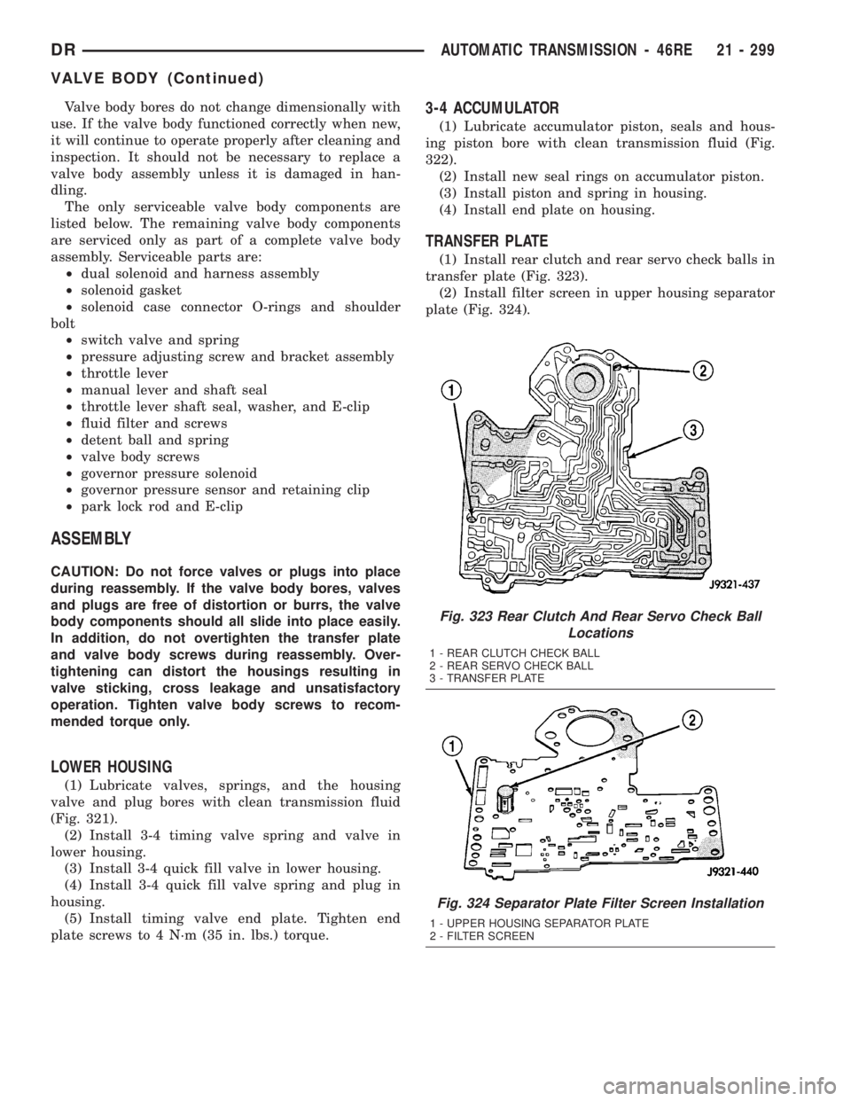
transfer plate (Fig. 323).
(2) Install filter screen in upper housing separator
plate (Fig. 324).
Fig. 323 Rear Clutch And Rear Servo Check Ball
Locations
1 - REAR CLUTCH CHECK BALL
2 - REAR SERVO CHECK BALL
3 - TRANSFER PLATE
Fig. 324 Separator Plate Filter Screen Installation
1 - UPPER HOUSING SEPARATOR PLATE
2 - FILTER SCREEN
DRAUTOMATIC TRANSMISSION - 46RE 21 - 299
VALVE BODY (Continued)
Page 2145 of 2895
VALVE BODY FINAL
(1) Install boost valve, valve spring, retainer and
cover plate. Tighten cover plate screws to 4 N´m (35
in. lbs.) torque.
(2) Insert manual lever detent spring in upper
housing.
(3) Position detent ball on end of spring. Then hold
detent ball and spring in detent housing with
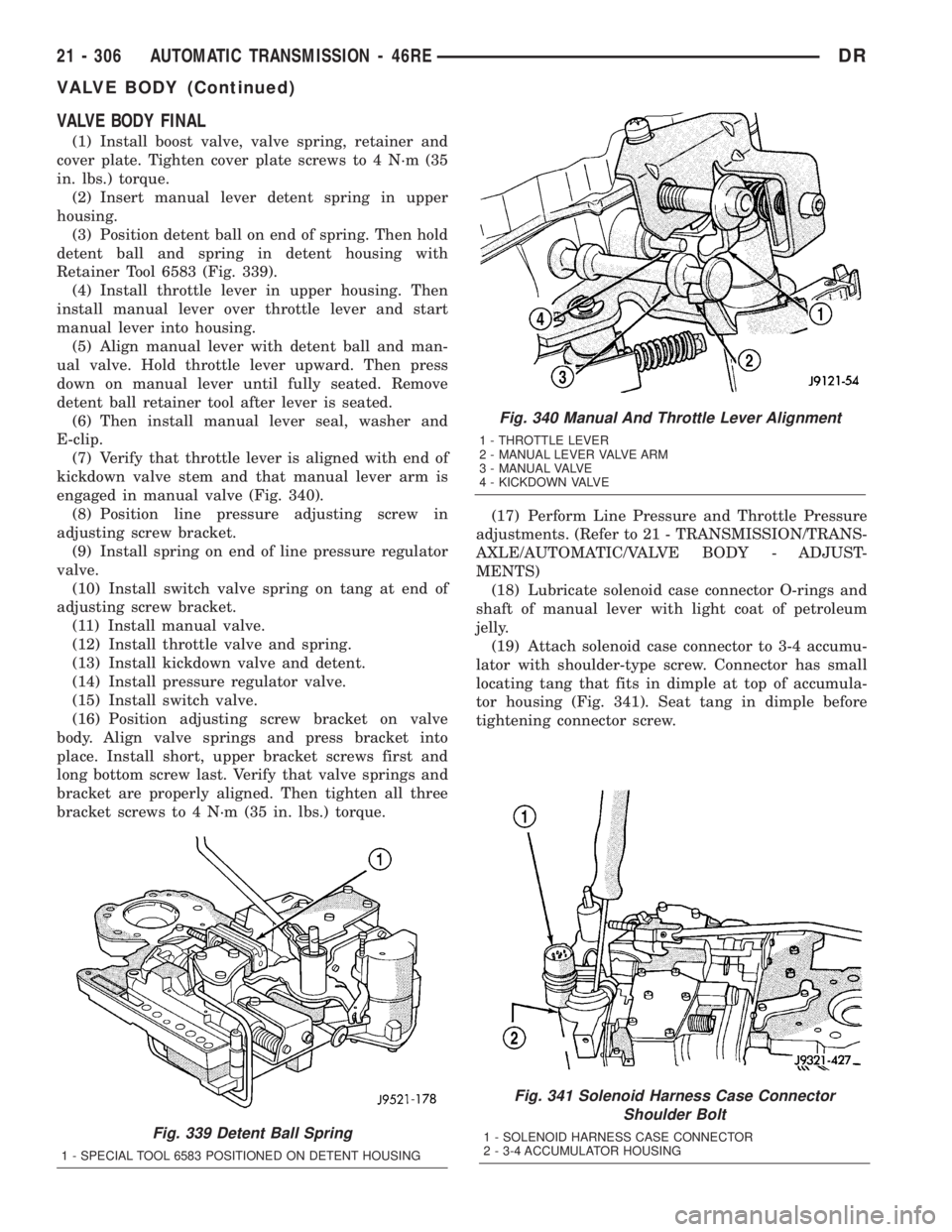
Retainer Tool 6583 (Fig. 339).
(4) Install throttle lever in upper housing. Then
install manual lever over throttle lever and start
manual lever into housing.
(5) Align manual lever with detent ball and man-
ual valve. Hold throttle lever upward. Then press
down on manual lever until fully seated. Remove
detent ball retainer tool after lever is seated.
(6) Then install manual lever seal, washer and
E-clip.
(7) Verify that throttle lever is aligned with end of
kickdown valve stem and that manual lever arm is
engaged in manual valve (Fig. 340).
(8) Position line pressure adjusting screw in
adjusting screw bracket.
(9) Install spring on end of line pressure regulator
valve.
(10) Install switch valve spring on tang at end of
adjusting screw bracket.
(11) Install manual valve.
(12) Install throttle valve and spring.
(13) Install kickdown valve and detent.
(14) Install pressure regulator valve.
(15) Install switch valve.
(16) Position adjusting screw bracket on valve
body. Align valve springs and press bracket into
place. Install short, upper bracket screws first and
long bottom screw last. Verify that valve springs and
bracket are properly aligned. Then tighten all three
bracket screws to 4 N´m (35 in. lbs.) torque.(17) Perform Line Pressure and Throttle Pressure
adjustments. (Refer to 21 - TRANSMISSION/TRANS-
AXLE/AUTOMATIC/VALVE BODY - ADJUST-
MENTS)
(18) Lubricate solenoid case connector O-rings and
shaft of manual lever with light coat of petroleum
jelly.
(19) Attach solenoid case connector to 3-4 accumu-
lator with shoulder-type screw. Connector has small
locating tang that fits in dimple at top of accumula-
tor housing (Fig. 341). Seat tang in dimple before
tightening connector screw.
Fig. 339 Detent Ball Spring
1 - SPECIAL TOOL 6583 POSITIONED ON DETENT HOUSING
Fig. 340 Manual And Throttle Lever Alignment
1 - THROTTLE LEVER
2 - MANUAL LEVER VALVE ARM
3 - MANUAL VALVE
4 - KICKDOWN VALVE
Fig. 341 Solenoid Harness Case Connector
Shoulder Bolt
1 - SOLENOID HARNESS CASE CONNECTOR
2 - 3-4 ACCUMULATOR HOUSING
21 - 306 AUTOMATIC TRANSMISSION - 46REDR
VALVE BODY (Continued)
Page 2146 of 2895
(20) Install solenoid assembly and gasket. Tighten
solenoid attaching screws to 8 N´m (72 in. lbs.)
torque.
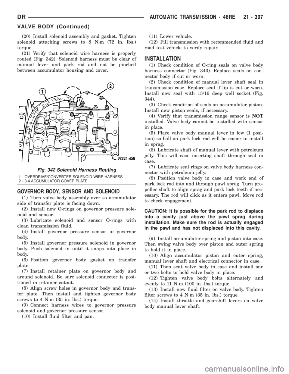
(21) Verify that solenoid wire harness is properly
routed (Fig. 342). Solenoid harness must be clear of
manual lever and park rod and not be pinched
between accumulator housing and cover.
GOVERNOR BODY, SENSOR AND SOLENOID
(1) Turn valve body assembly over so accumulator
side of transfer plate is facing down.
(2) Install new O-rings on governor pressure sole-
noid and sensor.
(3) Lubricate solenoid and sensor O-rings with
clean transmission fluid.
(4) Install governor pressure sensor in governor
body.
(5) Install governor pressure solenoid in governor
body. Push solenoid in until it snaps into place in
body.
(6) Position governor body gasket on transfer
plate.
(7) Install retainer plate on governor body and
around solenoid. Be sure solenoid connector is posi-
tioned in retainer cutout.
(8) Align screw holes in governor body and trans-
fer plate. Then install and tighten governor body
screws to 4 N´m (35 in. lbs.) torque.
(9) Connect harness wires to governor pressure
solenoid and governor pressure sensor.
(10) Install fluid filter and pan.(11) Lower vehicle.
(12) Fill transmission with recommended fluid and
road test vehicle to verify repair.
INSTALLATION
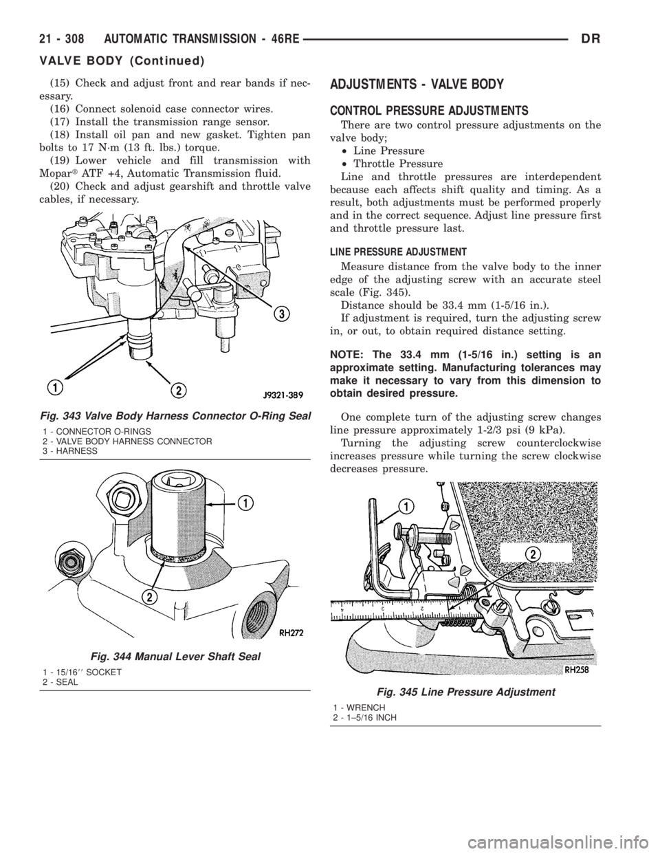
(1) Check condition of O-ring seals on valve body
harness connector (Fig. 343). Replace seals on con-
nector body if cut or worn.
(2) Check condition of manual lever shaft seal in
transmission case. Replace seal if lip is cut or worn.
Install new seal with 15/16 deep well socket (Fig.
344).
(3) Check condition of seals on accumulator piston.
Install new piston seals, if necessary.
(4) Verify that transmission range sensor isNOT
installed. Valve body cannot be installed with sensor
in place.
(5) Place valve body manual lever in low (1 posi-
tion) so ball on park lock rod will be easier to install
in sprag.
(6) Lubricate shaft of manual lever with petroleum
jelly. This will ease inserting shaft through seal in
case.
(7) Lubricate seal rings on valve body harness con-
nector with petroleum jelly.
(8) Position valve body in case and work end of
park lock rod into and through pawl sprag. Turn pro-
peller shaft to align sprag and park lock teeth if nec-
essary. The rod will click as it enters pawl. Move rod
to check engagement.
CAUTION: It is possible for the park rod to displace
into a cavity just above the pawl sprag during
installation. Make sure the rod is actually engaged
in the pawl and has not displaced into this cavity.
(9) Install accumulator spring and piston into case.
Then swing valve body over piston and outer spring
to hold it in place.
(10) Align accumulator piston and outer spring,
manual lever shaft and electrical connector in case.
(11) Then seat valve body in case and install one
or two bolts to hold valve body in place.
(12) Tighten valve body bolts alternately and
evenly to 11 N´m (100 in. lbs.) torque.
(13) Install new fluid filter on valve body. Tighten
filter screws to 4 N´m (35 in. lbs.) torque.
(14) Install throttle and gearshift levers on valve
body manual lever shaft.
Fig. 342 Solenoid Harness Routing
1 - OVERDRIVE/CONVERTER SOLENOID WIRE HARNESS
2 - 3-4 ACCUMULATOR COVER PLATE
DRAUTOMATIC TRANSMISSION - 46RE 21 - 307
VALVE BODY (Continued)
Page 2147 of 2895
(15) Check and adjust front and rear bands if nec-
essary.
(16) Connect solenoid case connector wires.
(17) Install the transmission range sensor.
(18) Install oil pan and new gasket. Tighten pan
bolts to 17 N´m (13 ft. lbs.) torque.
(19) Lower vehicle and fill transmission with
MopartATF +4, Automatic Transmission fluid.
(20) Check and adjust gearshift and throttle valve
cables, if necessary.ADJUSTMENTS - VALVE BODY
CONTROL PRESSURE ADJUSTMENTS
There are two control pressure adjustments on the
valve body;
²Line Pressure
²Throttle Pressure
Line and throttle pressures are interdependent
because each affects shift quality and timing. As a
result, both adjustments must be performed properly
and in the correct sequence. Adjust line pressure first
and throttle pressure last.
LINE PRESSURE ADJUSTMENT
Measure distance from the valve body to the inner
edge of the adjusting screw with an accurate steel
scale (Fig. 345).
Distance should be 33.4 mm (1-5/16 in.).
If adjustment is required, turn the adjusting screw
in, or out, to obtain required distance setting.
NOTE: The 33.4 mm (1-5/16 in.) setting is an
approximate setting. Manufacturing tolerances may
make it necessary to vary from this dimension to
obtain desired pressure.
One complete turn of the adjusting screw changes
line pressure approximately 1-2/3 psi (9 kPa).
Turning the adjusting screw counterclockwise
increases pressure while turning the screw clockwise
decreases pressure.
Fig. 343 Valve Body Harness Connector O-Ring Seal
1 - CONNECTOR O-RINGS
2 - VALVE BODY HARNESS CONNECTOR
3 - HARNESS
Fig. 344 Manual Lever Shaft Seal
1 - 15/1688SOCKET
2 - SEAL
Fig. 345 Line Pressure Adjustment
1 - WRENCH
2 - 1±5/16 INCH
21 - 308 AUTOMATIC TRANSMISSION - 46REDR
VALVE BODY (Continued)
Page 2170 of 2895
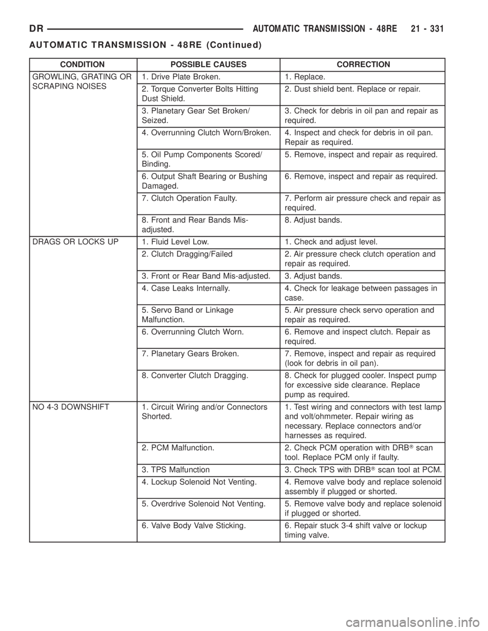
CONDITION POSSIBLE CAUSES CORRECTION
GROWLING, GRATING OR
SCRAPING NOISES1. Drive Plate Broken. 1. Replace.
2. Torque Converter Bolts Hitting
Dust Shield.2. Dust shield bent. Replace or repair.
3. Planetary Gear Set Broken/
Seized.3. Check for debris in oil pan and repair as
required.
4. Overrunning Clutch Worn/Broken. 4. Inspect and check for debris in oil pan.
Repair as required.
5. Oil Pump Components Scored/
Binding.5. Remove, inspect and repair as required.
6. Output Shaft Bearing or Bushing
Damaged.6. Remove, inspect and repair as required.
7. Clutch Operation Faulty. 7. Perform air pressure check and repair as
required.
8. Front and Rear Bands Mis-
adjusted.8. Adjust bands.
DRAGS OR LOCKS UP 1. Fluid Level Low. 1. Check and adjust level.
2. Clutch Dragging/Failed 2. Air pressure check clutch operation and
repair as required.
3. Front or Rear Band Mis-adjusted. 3. Adjust bands.
4. Case Leaks Internally. 4. Check for leakage between passages in
case.
5. Servo Band or Linkage
Malfunction.5. Air pressure check servo operation and
repair as required.
6. Overrunning Clutch Worn. 6. Remove and inspect clutch. Repair as
required.
7. Planetary Gears Broken. 7. Remove, inspect and repair as required
(look for debris in oil pan).
8. Converter Clutch Dragging. 8. Check for plugged cooler. Inspect pump
for excessive side clearance. Replace
pump as required.
NO 4-3 DOWNSHIFT 1. Circuit Wiring and/or Connectors
Shorted.1. Test wiring and connectors with test lamp
and volt/ohmmeter. Repair wiring as
necessary. Replace connectors and/or
harnesses as required.
2. PCM Malfunction. 2. Check PCM operation with DRBTscan
tool. Replace PCM only if faulty.
3. TPS Malfunction 3. Check TPS with DRBTscan tool at PCM.
4. Lockup Solenoid Not Venting. 4. Remove valve body and replace solenoid
assembly if plugged or shorted.
5. Overdrive Solenoid Not Venting. 5. Remove valve body and replace solenoid
if plugged or shorted.
6. Valve Body Valve Sticking. 6. Repair stuck 3-4 shift valve or lockup
timing valve.
DRAUTOMATIC TRANSMISSION - 48RE 21 - 331
AUTOMATIC TRANSMISSION - 48RE (Continued)
Page 2171 of 2895
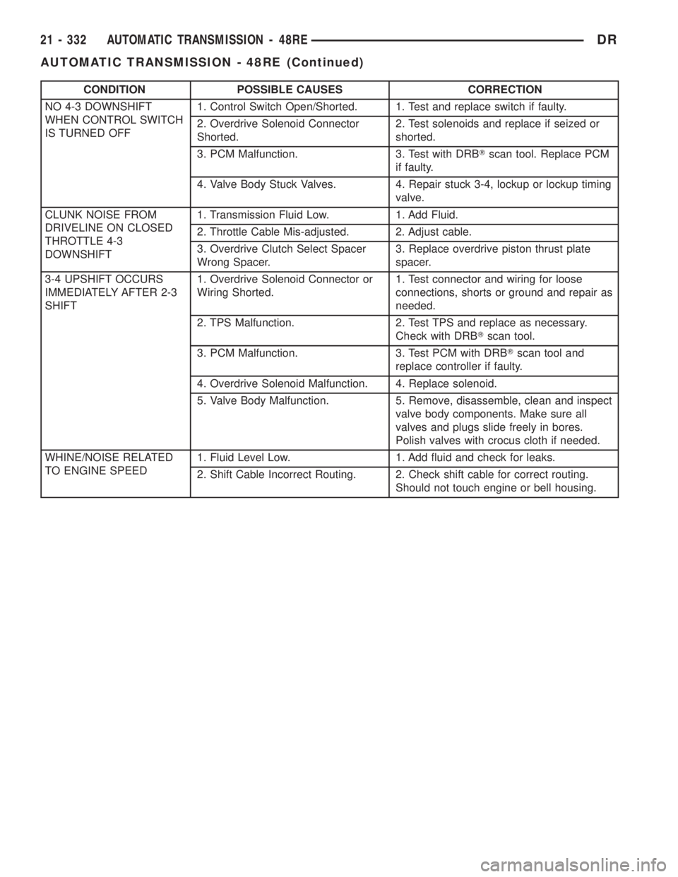
CONDITION POSSIBLE CAUSES CORRECTION
NO 4-3 DOWNSHIFT
WHEN CONTROL SWITCH
IS TURNED OFF1. Control Switch Open/Shorted. 1. Test and replace switch if faulty.
2. Overdrive Solenoid Connector
Shorted.2. Test solenoids and replace if seized or
shorted.
3. PCM Malfunction. 3. Test with DRBTscan tool. Replace PCM
if faulty.
4. Valve Body Stuck Valves. 4. Repair stuck 3-4, lockup or lockup timing
valve.
CLUNK NOISE FROM
DRIVELINE ON CLOSED
THROTTLE 4-3
DOWNSHIFT1. Transmission Fluid Low. 1. Add Fluid.
2. Throttle Cable Mis-adjusted. 2. Adjust cable.
3. Overdrive Clutch Select Spacer
Wrong Spacer.3. Replace overdrive piston thrust plate
spacer.
3-4 UPSHIFT OCCURS
IMMEDIATELY AFTER 2-3
SHIFT1. Overdrive Solenoid Connector or
Wiring Shorted.1. Test connector and wiring for loose
connections, shorts or ground and repair as
needed.
2. TPS Malfunction. 2. Test TPS and replace as necessary.
Check with DRBTscan tool.
3. PCM Malfunction. 3. Test PCM with DRBTscan tool and
replace controller if faulty.
4. Overdrive Solenoid Malfunction. 4. Replace solenoid.
5. Valve Body Malfunction. 5. Remove, disassemble, clean and inspect
valve body components. Make sure all
valves and plugs slide freely in bores.
Polish valves with crocus cloth if needed.
WHINE/NOISE RELATED
TO ENGINE SPEED1. Fluid Level Low. 1. Add fluid and check for leaks.
2. Shift Cable Incorrect Routing. 2. Check shift cable for correct routing.
Should not touch engine or bell housing.
21 - 332 AUTOMATIC TRANSMISSION - 48REDR
AUTOMATIC TRANSMISSION - 48RE (Continued)
Page 2173 of 2895
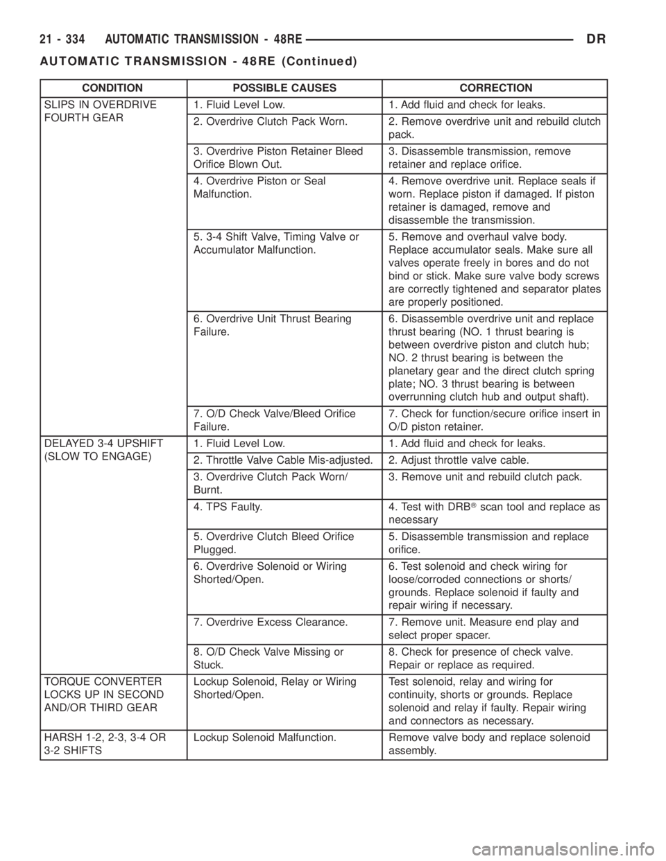
CONDITION POSSIBLE CAUSES CORRECTION
SLIPS IN OVERDRIVE
FOURTH GEAR1. Fluid Level Low. 1. Add fluid and check for leaks.
2. Overdrive Clutch Pack Worn. 2. Remove overdrive unit and rebuild clutch
pack.
3. Overdrive Piston Retainer Bleed
Orifice Blown Out.3. Disassemble transmission, remove
retainer and replace orifice.
4. Overdrive Piston or Seal
Malfunction.4. Remove overdrive unit. Replace seals if
worn. Replace piston if damaged. If piston
retainer is damaged, remove and
disassemble the transmission.
5. 3-4 Shift Valve, Timing Valve or
Accumulator Malfunction.5. Remove and overhaul valve body.
Replace accumulator seals. Make sure all
valves operate freely in bores and do not
bind or stick. Make sure valve body screws
are correctly tightened and separator plates
are properly positioned.
6. Overdrive Unit Thrust Bearing
Failure.6. Disassemble overdrive unit and replace
thrust bearing (NO. 1 thrust bearing is
between overdrive piston and clutch hub;
NO. 2 thrust bearing is between the
planetary gear and the direct clutch spring
plate; NO. 3 thrust bearing is between
overrunning clutch hub and output shaft).
7. O/D Check Valve/Bleed Orifice
Failure.7. Check for function/secure orifice insert in
O/D piston retainer.
DELAYED 3-4 UPSHIFT
(SLOW TO ENGAGE)1. Fluid Level Low. 1. Add fluid and check for leaks.
2. Throttle Valve Cable Mis-adjusted. 2. Adjust throttle valve cable.
3. Overdrive Clutch Pack Worn/
Burnt.3. Remove unit and rebuild clutch pack.
4. TPS Faulty. 4. Test with DRBTscan tool and replace as
necessary
5. Overdrive Clutch Bleed Orifice
Plugged.5. Disassemble transmission and replace
orifice.
6. Overdrive Solenoid or Wiring
Shorted/Open.6. Test solenoid and check wiring for
loose/corroded connections or shorts/
grounds. Replace solenoid if faulty and
repair wiring if necessary.
7. Overdrive Excess Clearance. 7. Remove unit. Measure end play and
select proper spacer.
8. O/D Check Valve Missing or
Stuck.8. Check for presence of check valve.
Repair or replace as required.
TORQUE CONVERTER
LOCKS UP IN SECOND
AND/OR THIRD GEARLockup Solenoid, Relay or Wiring
Shorted/Open.Test solenoid, relay and wiring for
continuity, shorts or grounds. Replace
solenoid and relay if faulty. Repair wiring
and connectors as necessary.
HARSH 1-2, 2-3, 3-4 OR
3-2 SHIFTSLockup Solenoid Malfunction. Remove valve body and replace solenoid
assembly.
21 - 334 AUTOMATIC TRANSMISSION - 48REDR
AUTOMATIC TRANSMISSION - 48RE (Continued)