2003 DODGE RAM Abs control module
[x] Cancel search: Abs control modulePage 2216 of 2895
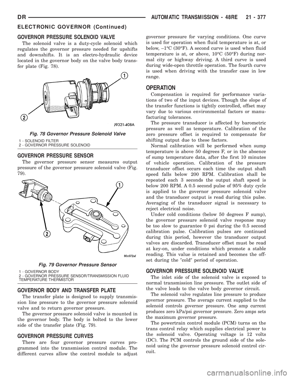
GOVERNOR PRESSURE SOLENOID VALVE
The solenoid valve is a duty-cycle solenoid which
regulates the governor pressure needed for upshifts
and downshifts. It is an electro-hydraulic device
located in the governor body on the valve body trans-
fer plate (Fig. 78).
GOVERNOR PRESSURE SENSOR
The governor pressure sensor measures output
pressure of the governor pressure solenoid valve (Fig.
79).
GOVERNOR BODY AND TRANSFER PLATE
The transfer plate is designed to supply transmis-
sion line pressure to the governor pressure solenoid
valve and to return governor pressure.
The governor pressure solenoid valve is mounted in
the governor body. The body is bolted to the lower
side of the transfer plate (Fig. 79).
GOVERNOR PRESSURE CURVES
There are four governor pressure curves pro-
grammed into the transmission control module. The
different curves allow the control module to adjustgovernor pressure for varying conditions. One curve
is used for operation when fluid temperature is at, or
below, ±1ÉC (30ÉF). A second curve is used when fluid
temperature is at, or above, 10ÉC (50ÉF) during nor-
mal city or highway driving. A third curve is used
during wide-open throttle operation. The fourth curve
is used when driving with the transfer case in low
range.
OPERATION
Compensation is required for performance varia-
tions of two of the input devices. Though the slope of
the transfer functions is tightly controlled, offset may
vary due to various environmental factors or manu-
facturing tolerances.
The pressure transducer is affected by barometric
pressure as well as temperature. Calibration of the
zero pressure offset is required to compensate for
shifting output due to these factors.
Normal calibration will be performed when sump
temperature is above 50 degrees F, or in the absence
of sump temperature data, after the first 10 minutes
of vehicle operation. Calibration of the pressure
transducer offset occurs each time the output shaft
speed falls below 200 RPM. Calibration shall be
repeated each 3 seconds the output shaft speed is
below 200 RPM. A 0.5 second pulse of 95% duty cycle
is applied to the governor pressure solenoid valve
and the transducer output is read during this pulse.
Averaging of the transducer signal is necessary to
reject electrical noise.
Under cold conditions (below 50 degrees F sump),
the governor pressure solenoid valve response may
be too slow to guarantee 0 psi during the 0.5 second
calibration pulse. Calibration pulses are continued
during this period, however the transducer output
valves are discarded. Transducer offset must be read
at key-on, under conditions which promote a stable
reading. This value is retained and becomes the off-
set during the9cold9period of operation.
GOVERNOR PRESSURE SOLENOID VALVE
The inlet side of the solenoid valve is exposed to
normal transmission line pressure. The outlet side of
the valve leads to the valve body governor circuit.
The solenoid valve regulates line pressure to produce
governor pressure. The average current supplied to the
solenoid controls governor pressure. One amp current
produces zero kPa/psi governor pressure. Zero amps sets
the maximum governor pressure.
The powertrain control module (PCM) turns on the
trans control relay which supplies electrical power to
the solenoid valve. Operating voltage is 12 volts
(DC). The PCM controls the ground side of the sole-
noid using the governor pressure solenoid control cir-
cuit.
Fig. 78 Governor Pressure Solenoid Valve
1 - SOLENOID FILTER
2 - GOVERNOR PRESSURE SOLENOID
Fig. 79 Governor Pressure Sensor
1 - GOVERNOR BODY
2 - GOVERNOR PRESSURE SENSOR/TRANSMISSION FLUID
TEMPERATURE THERMISTOR
DRAUTOMATIC TRANSMISSION - 48RE 21 - 377
ELECTRONIC GOVERNOR (Continued)
Page 2790 of 2895
INSTALLATION
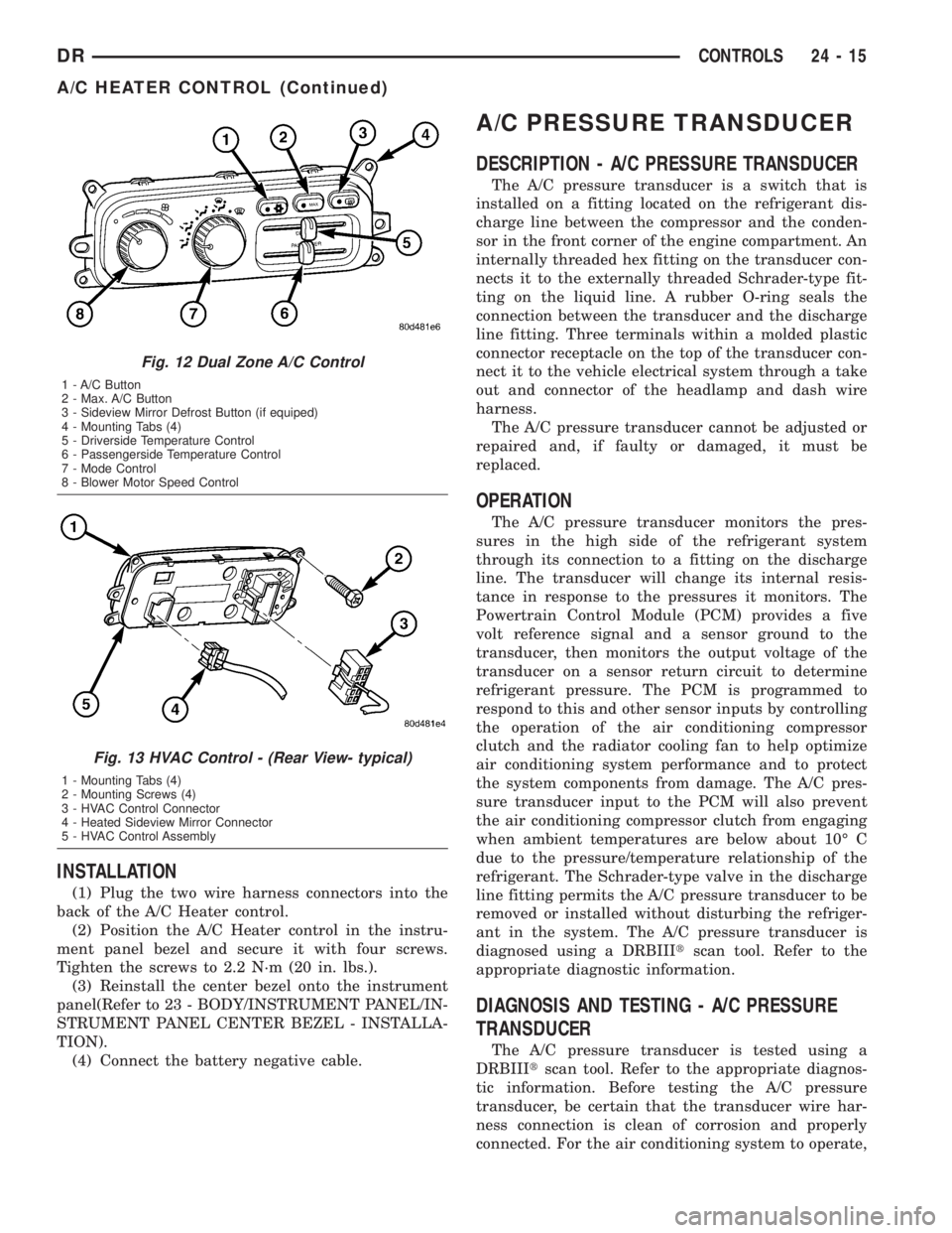
(1) Plug the two wire harness connectors into the
back of the A/C Heater control.
(2) Position the A/C Heater control in the instru-
ment panel bezel and secure it with four screws.
Tighten the screws to 2.2 N´m (20 in. lbs.).
(3) Reinstall the center bezel onto the instrument
panel(Refer to 23 - BODY/INSTRUMENT PANEL/IN-
STRUMENT PANEL CENTER BEZEL - INSTALLA-
TION).
(4) Connect the battery negative cable.
A/C PRESSURE TRANSDUCER
DESCRIPTION - A/C PRESSURE TRANSDUCER
The A/C pressure transducer is a switch that is
installed on a fitting located on the refrigerant dis-
charge line between the compressor and the conden-
sor in the front corner of the engine compartment. An
internally threaded hex fitting on the transducer con-
nects it to the externally threaded Schrader-type fit-
ting on the liquid line. A rubber O-ring seals the
connection between the transducer and the discharge
line fitting. Three terminals within a molded plastic
connector receptacle on the top of the transducer con-
nect it to the vehicle electrical system through a take
out and connector of the headlamp and dash wire
harness.
The A/C pressure transducer cannot be adjusted or
repaired and, if faulty or damaged, it must be
replaced.
OPERATION
The A/C pressure transducer monitors the pres-
sures in the high side of the refrigerant system
through its connection to a fitting on the discharge
line. The transducer will change its internal resis-
tance in response to the pressures it monitors. The
Powertrain Control Module (PCM) provides a five
volt reference signal and a sensor ground to the
transducer, then monitors the output voltage of the
transducer on a sensor return circuit to determine
refrigerant pressure. The PCM is programmed to
respond to this and other sensor inputs by controlling
the operation of the air conditioning compressor
clutch and the radiator cooling fan to help optimize
air conditioning system performance and to protect
the system components from damage. The A/C pres-
sure transducer input to the PCM will also prevent
the air conditioning compressor clutch from engaging
when ambient temperatures are below about 10É C
due to the pressure/temperature relationship of the
refrigerant. The Schrader-type valve in the discharge
line fitting permits the A/C pressure transducer to be
removed or installed without disturbing the refriger-
ant in the system. The A/C pressure transducer is
diagnosed using a DRBIIItscan tool. Refer to the
appropriate diagnostic information.
DIAGNOSIS AND TESTING - A/C PRESSURE
TRANSDUCER
The A/C pressure transducer is tested using a
DRBIIItscan tool. Refer to the appropriate diagnos-
tic information. Before testing the A/C pressure
transducer, be certain that the transducer wire har-
ness connection is clean of corrosion and properly
connected. For the air conditioning system to operate,
Fig. 12 Dual Zone A/C Control
1 - A/C Button
2 - Max. A/C Button
3 - Sideview Mirror Defrost Button (if equiped)
4 - Mounting Tabs (4)
5 - Driverside Temperature Control
6 - Passengerside Temperature Control
7 - Mode Control
8 - Blower Motor Speed Control
Fig. 13 HVAC Control - (Rear View- typical)
1 - Mounting Tabs (4)
2 - Mounting Screws (4)
3 - HVAC Control Connector
4 - Heated Sideview Mirror Connector
5 - HVAC Control Assembly
DRCONTROLS 24 - 15
A/C HEATER CONTROL (Continued)
Page 2791 of 2895
an A/C pressure transducer voltage reading between
0.451 and 4.519 volts is required. Voltages outside
this range indicate a low or high refrigerant system
pressure condition to the Powertrain Control Module
(PCM). The PCM is programmed to respond to a low
or high refrigerant system pressure by suppressing
operation of the compressor. Refer to the A/C Pres-
sure Transducer Voltage table for the possible condi-
tion indicated by the transducer voltage readings.
A/C PRESSURE TRANSDUCER VOLTAGE
VOLTAGE POSSIBLE INDICATION
0.0 1. NO SENSOR SUPPLY
VOLTAGE FROM PCM.
2. SHORTED SENSOR CIRCUIT.
3. FAULTY TRANSDUCER.
0.150 TO 0.450 1. AMBIENT TEMPERATURE
BELOW 10É C (50É F).
2. LOW REFRIGERANT
SYSTEM PRESSURE.
0.451 TO 4.519 1. NORMAL REFRIGERANT
SYSTEM PRESSURE.
4.520 TO 4.850 1. HIGH REFRIGERANT
SYSTEM PRESSURE.
5.0 1. OPEN SENSOR CIRCUIT.
2. FAULTY TRANSDUCER.
REMOVAL
(1) Disconnect and isolate the battery negative
cable.
(2) Disconnect the wire harness connector for the
A/C pressure transducer from the transducer connec-
tor receptacle.
(3) Using an open end wrench, unscrew the A/C
pressure transducer from the fitting on the discharge
line between the compressor and the condenser.
(4) Remove the seal from the A/C pressure trans-
ducer fitting and discard.
INSTALLATION
(1) Lubricate a new rubber O-ring seal with clean
refrigerant oil and install it on the A/C pressure
transducer fitting.
(2) Using an open end wrench, install and tighten
the A/C pressure transducer onto the fitting on the
discharge line between the compressor and the con-
denser.
(3) Reconnect the wire harness connector for the
A/C pressure transducer to the transducer connector
receptacle.
(4) Reconnect the battery negative cable.
BLEND DOOR ACTUATOR
DESCRIPTION
The blend door actuators are reversible, 12-volt
Direct Current (DC), servo motors. Models with the
single zone heater and air conditioner system have a
single blend air door, which is controlled by a single
blend door actuator. Models with the optional dual
zone front heater and air conditioner system have
dual blend air doors, which are controlled by two
blend door actuators. The single zone blend door
actuator is located on the driver side end of the heat-
er-A/C housing unit, close to the dash panel. In the
dual zone system, the same blend door actuator used
for the single zone system becomes the driver side
blend door actuator, and is mechanically connected to
only the driver side blend air door. In the dual zone
system, a second separate blend door actuator is also
located on the top of the heater-A/C housing unit and
is mechanically connected to only the passenger side
blend air door.
The blend door actuators are interchangeable with
each other, as well as with the actuators for the
mode door and the recirculation air door. Each actua-
tor is contained within an identical black molded
plastic housing with an integral wire connector
receptacle. Two integral mounting tabs allow the
actuator to be secured with two screws to the heater-
A/C unit housing. Each actuator also has an identical
output shaft with splines that connects it to the link-
age that drives the proper blend air door. The blend
door actuators do not require mechanical indexing to
the blend door linkage, as they are electronically cal-
ibrated by the heater-A/C control module. The blend
door actuators cannot be adjusted or repaired and, if
damaged or faulty, they must be replaced.
OPERATION
Each blend door actuator is connected to the heat-
er-A/C control module through the vehicle electrical
system by a dedicated two-wire take out and connec-
tor of the HVAC wire harness. The blend door actua-
tor can move the blend air door in two directions.
When the heater-A/C control module pulls the volt-
age on one side of the motor connection high and the
other connection low, the blend air door will move in
one direction. When the module reverses the polarity
of the voltage to the motor, the blend air door moves
in the opposite direction. When the module makes
the voltage to both connections high or both connec-
tions low, the blend air door stops and will not move.
These same motor connections also provide a feed-
back signal to the heater-A/C control module. This
feedback signal allows the module to monitor the
operation and relative positions of the blend door
actuator and the blend air door. The heater-A/C con-
24 - 16 CONTROLSDR
A/C PRESSURE TRANSDUCER (Continued)
Page 2797 of 2895
INSTALLATION
WARNING: ON VEHICLES EQUIPPED WITH AIR-
BAGS, DISABLE THE AIRBAG SYSTEM BEFORE
ATTEMPTING ANY STEERING WHEEL, STEERING
COLUMN, OR INSTRUMENT PANEL COMPONENT
DIAGNOSIS OR SERVICE. DISCONNECT AND ISO-
LATE THE BATTERY NEGATIVE (GROUND) CABLE,
THEN WAIT TWO MINUTES FOR THE AIRBAG SYS-
TEM CAPACITOR TO DISCHARGE BEFORE PER-
FORMING FURTHER DIAGNOSIS OR SERVICE. THIS
IS THE ONLY SURE WAY TO DISABLE THE AIRBAG
SYSTEM. FAILURE TO TAKE THE PROPER PRE-
CAUTIONS COULD RESULT IN ACCIDENTAL AIR-
BAG DEPLOYMENT AND POSSIBLE PERSONAL
INJURY.
(1) Position the mode door actuators onto the heat-
er/AC housing. If necessary, rotate the actuator
slightly to align the splines on the actuator output
shaft with those in the mode door linkage.
(2) Install and tighten the two screws that secure
the mode door actuators to the distribution housing.
Tighten the screws to 2 N´m (17 in. lbs.).
(3) Reconnect the HVAC wire harness connector
for the mode door actuators to the actuator connector
receptacle.
(4) Install the instrument panel assembly(Refer to
23 - BODY/INSTRUMENT PANEL/INSTRUMENT
PANEL ASSEMBLY - INSTALLATION).
(5) Reconnect the battery negative cable.
(6) Perform the heater-A/C control calibration pro-
cedure. (Refer to 24 - HEATING & AIR CONDITION-
ING/CONTROLS - FRONT/A/C-HEATER CONTROL
- STANDARD PROCEDURE - HEATER-A/C CON-
TROL CALIBRATION).
RECIRCULATION DOOR
ACTUATOR
DESCRIPTION
The recirculation door actuator is a reversible,
12-volt Direct Current (DC), servo motor. The single
recirculation door actuator is located on the passen-
ger side end of the heater-A/C housing unit. The
recirculation door actuator is mechanically connected
to the recirculation air door. The recirculation door
actuator is interchangeable with the actuators for the
blend air door(s) and the mode doors. Each actuator
is contained within an identical black molded plastic
housing with an integral wire connector receptacle.
Two integral mounting tabs allow the actuator to be
secured with two screws to the intake air housing.
Each actuator also has an identical output shaft with
splines that connects it to the linkage that drives therecirculation air door. The recirculation door actuator
does not require mechanical indexing to the recircu-
lation air door, as it is electronically calibrated by the
heater-A/C control module. The recirculation door
actuator cannot be adjusted or repaired and, if dam-
aged or faulty, it must be replaced.
OPERATION
The recirculation door actuator is connected to the
heater-A/C control module through the vehicle elec-
trical system by a dedicated two-wire take out and
connector of the HVAC wire harness. The recircula-
tion door actuator can move the recirculation door in
two directions. When the heater-A/C control module
pulls the voltage on one side of the motor connection
high and the other connection low, the recirculation
air door will move in one direction. When the module
reverses the polarity of the voltage to the motor, the
recirculation air door moves in the opposite direction.
When the module makes the voltage to both connec-
tions high or both connections low, the recirculation
air door stops and will not move. These same motor
connections also provide a feedback signal to the
heater-A/C control module. This feedback signal
allows the module to monitor the operation and rela-
tive position of the recirculation door actuator and
the recirculation air door. The heater-A/C control
module learns the recirculation air door stop posi-
tions during the calibration procedure and will store
a Diagnostic Trouble Code (DTC) for any problems it
detects in the recirculation door actuator circuits.
The recirculation door actuator can be diagnosed
using a DRBIIItscan tool. Refer to the appropriate
diagnostic information.
REMOVAL
WARNING: ON VEHICLES EQUIPPED WITH AIR-
BAGS, DISABLE THE AIRBAG SYSTEM BEFORE
ATTEMPTING ANY STEERING WHEEL, STEERING
COLUMN, OR INSTRUMENT PANEL COMPONENT
DIAGNOSIS OR SERVICE. DISCONNECT AND ISO-
LATE THE BATTERY NEGATIVE (GROUND) CABLE,
THEN WAIT TWO MINUTES FOR THE AIRBAG SYS-
TEM CAPACITOR TO DISCHARGE BEFORE PER-
FORMING FURTHER DIAGNOSIS OR SERVICE. THIS
IS THE ONLY SURE WAY TO DISABLE THE AIRBAG
SYSTEM. FAILURE TO TAKE THE PROPER PRE-
CAUTIONS COULD RESULT IN ACCIDENTAL AIR-
BAG DEPLOYMENT AND POSSIBLE PERSONAL
INJURY.
(1) Disconnect and isolate the battery negative
cable.
(2) Pull the carpet on the passenger side front
floor away from the dash panel far enough to access
the recirculation door actuator.
24 - 22 CONTROLSDR
MODE DOOR ACTUATOR (Continued)
Page 2833 of 2895
verter. The PCM calculates the A/F mixture from the
output of the O2S. A low voltage indicates high oxy-
gen content (lean mixture). A high voltage indicates a
low content of oxygen (rich mixture).
When the upstream O2S detects a lean condition,
there is an abundance of oxygen in the exhaust gas.
A functioning converter would store this oxygen so it
can use it for the oxidation of HC and CO. As the
converter absorbs the oxygen, there will be a lack of
oxygen downstream of the converter. The output of
the downstream O2S will indicate limited activity in
this condition.
As the converter loses the ability to store oxygen,
the condition can be detected from the behavior of
the downstream O2S. When the efficiency drops, no
chemical reaction takes place. This means the con-
centration of oxygen will be the same downstream as
upstream. The output voltage of the downstream
O2S copies the voltage of the upstream sensor. The
only difference is a time lag (seen by the PCM)
between the switching of the O2S's.
To monitor the system, the number of lean-to-rich
switches of upstream and downstream O2S's is
counted. The ratio of downstream switches to
upstream switches is used to determine whether the
catalyst is operating properly. An effective catalyst
will have fewer downstream switches than it has
upstream switches i.e., a ratio closer to zero. For a
totally ineffective catalyst, this ratio will be one-to-
one, indicating that no oxidation occurs in the device.
The system must be monitored so that when cata-
lyst efficiency deteriorates and exhaust emissions
increase to over the legal limit, the MIL will be illu-
minated.
DESCRIPTION - TRIP DEFINITION
The term ªTripº has different meanings depending
on what the circumstances are. If the MIL (Malfunc-
tion Indicator Lamp) is OFF, a Trip is defined as
when the Oxygen Sensor Monitor and the Catalyst
Monitor have been completed in the same drive cycle.
When any Emission DTC is set, the MIL on the
dash is turned ON. When the MIL is ON, it takes 3
good trips to turn the MIL OFF. In this case, it
depends on what type of DTC is set to know what a
ªTripº is.
For the Fuel Monitor or Mis-Fire Monitor (contin-
uous monitor), the vehicle must be operated in the
ªSimilar Condition Windowº for a specified amount of
time to be considered a Good Trip.
If a Non-Contiuous OBDII Monitor fails twice in a
row and turns ON the MIL, re-running that monitor
which previously failed, on the next start-up and
passing the monitor, is considered to be a Good Trip.
These will include the following:
²Oxygen Sensor²Catalyst Monitor
²Purge Flow Monitor
²Leak Detection Pump Monitor (if equipped)
²EGR Monitor (if equipped)
²Oxygen Sensor Heater Monitor
If any other Emission DTC is set (not an OBDII
Monitor), a Good Trip is considered to be when the
Oxygen Sensor Monitor and Catalyst Monitor have
been completed; or 2 Minutes of engine run time if
the Oxygen Sensor Monitor or Catalyst Monitor have
been stopped from running.
It can take up to 2 Failures in a row to turn on the
MIL. After the MIL is ON, it takes 3 Good Trips to
turn the MIL OFF. After the MIL is OFF, the PCM
will self-erase the DTC after 40 Warm-up cycles. A
Warm-up cycle is counted when the ECT (Engine
Coolant Temperature Sensor) has crossed 160ÉF and
has risen by at least 40ÉF since the engine has been
started.
DESCRIPTION - COMPONENT MONITORS
There are several components that will affect vehi-
cle emissions if they malfunction. If one of these com-
ponents malfunctions the Malfunction Indicator
Lamp (MIL) will illuminate.
Some of the component monitors are checking for
proper operation of the part. Electrically operated
components now have input (rationality) and output
(functionality) checks. Previously, a component like
the Throttle Position sensor (TPS) was checked by
the PCM for an open or shorted circuit. If one of
these conditions occurred, a DTC was set. Now there
is a check to ensure that the component is working.
This is done by watching for a TPS indication of a
greater or lesser throttle opening than MAP and
engine rpm indicate. In the case of the TPS, if engine
vacuum is high and engine rpm is 1600 or greater,
and the TPS indicates a large throttle opening, a
DTC will be set. The same applies to low vacuum if
the TPS indicates a small throttle opening.
All open/short circuit checks, or any component
that has an associated limp-in, will set a fault after 1
trip with the malfunction present. Components with-
out an associated limp-in will take two trips to illu-
minate the MIL.
OPERATION
OPERATION
The Powertrain Control Module (PCM) monitors
many different circuits in the fuel injection, ignition,
emission and engine systems. If the PCM senses a
problem with a monitored circuit often enough to
indicate an actual problem, it stores a Diagnostic
Trouble Code (DTC) in the PCM's memory. If the
25 - 4 EMISSIONS CONTROLDR
EMISSIONS CONTROL (Continued)
Page 2856 of 2895
ABS - DESCRIPTION, BRAKES...........5-39
ABS - OPERATION, BRAKES.............5-39
ABS BRAKE BLEEDING - STANDARD
PROCEDURE.........................5-40
ABS INDICATOR - DESCRIPTION.........8J-17
ABS INDICATOR - OPERATION..........8J-17
A/C APPLICATION TABLE,
SPECIFICATIONS......................24-7
A/C COMPRESSOR CLUTCH -
DESCRIPTION........................24-9
A/C COMPRESSOR CLUTCH -
INSPECTION........................24-12
A/C COMPRESSOR CLUTCH -
INSTALLATION.......................24-12
A/C COMPRESSOR CLUTCH -
OPERATION..........................24-9
A/C COMPRESSOR CLUTCH - REMOVAL . . 24-10
A/C COMPRESSOR CLUTCH BREAK-IN -
STANDARD PROCEDURE...............24-10
A/C COMPRESSOR CLUTCH COIL -
DIAGNOSIS AND TESTING.............24-10
A/C COMPRESSOR CLUTCH RELAY -
DESCRIPTION.......................24-13
A/C COMPRESSOR CLUTCH RELAY -
INSTALLATION.......................24-14
A/C COMPRESSOR CLUTCH RELAY -
OPERATION.........................24-13
A/C COMPRESSOR CLUTCH RELAY -
REMOVAL..........................24-14
A/C COMPRESSOR NOISE - DIAGNOSIS
AND TESTING.......................24-36
A/C CONDENSER - DESCRIPTION.........24-39
A/C CONDENSER - OPERATION..........24-39
A/C EVAPORATOR - DESCRIPTION.......24-47
A/C EVAPORATOR - INSTALLATION......24-47
A/C EVAPORATOR - OPERATION.........24-47
A/C EVAPORATOR - REMOVAL..........24-47
A/C HEATER CONTROL - DESCRIPTION . . . 24-14
A/C HEATER CONTROL - INSTALLATION . . . 24-15
A/C HEATER CONTROL - REMOVAL......24-14
A/C ORIFICE TUBE - DESCRIPTION.......24-48
A/C ORIFICE TUBE - INSTALLATION......24-49
A/C ORIFICE TUBE - OPERATION........24-48
A/C ORIFICE TUBE - REMOVAL..........24-49
A/C PERFORMANCE - DIAGNOSIS AND
TESTING............................24-2
A/C PRESSURE TRANSDUCER -
DESCRIPTION.......................24-15
A/C PRESSURE TRANSDUCER -
DIAGNOSIS AND TESTING.............24-15
A/C PRESSURE TRANSDUCER -
INSTALLATION.......................24-16
A/C PRESSURE TRANSDUCER -
OPERATION.........................24-15
A/C PRESSURE TRANSDUCER -
REMOVAL..........................24-16
ACCELERATOR PEDAL - INSTALLATION . . . 14-24
ACCELERATOR PEDAL - REMOVAL.......14-24
ACCELERATOR PEDAL POSITION
SENSOR - DESCRIPTION...............14-25
ACCELERATOR PEDAL POSITION
SENSOR - INSTALLATION..............14-25
ACCELERATOR PEDAL POSITION
SENSOR - OPERATION................14-25
ACCELERATOR PEDAL POSITION
SENSOR - REMOVAL..................14-25
ACCESSORY DRIVE BELT - DIAGNOSIS
AND TESTING................7-25,7-28,7-31
ACCUMULATOR - DESCRIPTION.........24-49
ACCUMULATOR - DESCRIPTION
. . 21-191,21-372
ACCUMULATOR - INSPECTION
. . . 21-192,21-373
ACCUMULATOR - INSTALLATION
........24-50
ACCUMULATOR - OPERATION
..........24-49
ACCUMULATOR - OPERATION
....21-192,21-373
ACCUMULATOR - REMOVAL
............24-49
ACM COVER - INSTALLATION
............8O-9
ACM COVER - REMOVAL
...............8O-9
ACTUATION TEST MODE - DESCRIPTION,
CIRCUIT
.............................25-1
ACTUATOR - DESCRIPTION, BLEND
DOOR
.............................24-16
ACTUATOR - DESCRIPTION, FUEL
CONTROL
..........................14-85
ACTUATOR - DESCRIPTION, MODE
DOOR
.............................24-20
ACTUATOR - DESCRIPTION,
RECIRCULATION DOOR
................24-22ACTUATOR - INSTALLATION, BLEND
DOOR.............................24-17
ACTUATOR - INSTALLATION, FLOOR -
DEFROST DOOR.....................24-20
ACTUATOR - INSTALLATION, FUEL
CONTROL..........................14-85
ACTUATOR - INSTALLATION, INSIDE
HANDLE.......................23-22,23-32
ACTUATOR - INSTALLATION, MODE
DOOR.............................24-22
ACTUATOR - INSTALLATION,
RECIRCULATION DOOR................24-23
ACTUATOR - OPERATION, BLEND DOOR . . 24-16
ACTUATOR - OPERATION, FUEL
CONTROL..........................14-85
ACTUATOR - OPERATION, MODE DOOR . . . 24-21
ACTUATOR - OPERATION,
RECIRCULATION DOOR................24-22
ACTUATOR - REMOVAL, BLEND DOOR....24-17
ACTUATOR - REMOVAL, FLOOR -
DEFROST DOOR.....................24-19
ACTUATOR - REMOVAL, FUEL CONTROL . . 14-85
ACTUATOR - REMOVAL, INSIDE HANDLE . 23-22,
23-31
ACTUATOR - REMOVAL, MODE DOOR....24-21
ACTUATOR - REMOVAL, RECIRCULATION
DOOR.............................24-22
ADAPTER HOUSING SEAL -
INSTALLATION...........21-127,21-539,21-83
ADAPTER HOUSING SEAL - REMOVAL . . 21-127,
21-539,21-83
ADAPTER MOUNT - INSTALLATION, DISC
BRAKE CALIPER......................5-17
ADDING ADDITIONAL COOLANT -
STANDARD PROCEDURE................7-19
ADDITIONAL COOLANT - STANDARD
PROCEDURE, ADDING..................7-19
ADHESIVE LOCATIONS -
SPECIFICATIONS, STRUCTURAL........23-113
ADJUSTABLE PEDAL MOTOR -
DESCRIPTION........................5-24
ADJUSTABLE PEDAL MOTOR -
INSTALLATION........................5-24
ADJUSTABLE PEDAL MOTOR - REMOVAL . . 5-24
ADJUSTABLE PEDAL SWITCH -
INSTALLATION.........................5-6
ADJUSTABLE PEDAL SWITCH -
REMOVAL............................5-6
ADJUSTER - DIAGNOSIS AND TESTING,
HYDRAULIC LASH................9-124,9-31
ADJUSTER - INSTALLATION, SEAT BELT
TURNING LOOP.....................8O-50
ADJUSTER - REMOVAL, SEAT BELT
TURNING LOOP.....................8O-50
ADJUSTER ASSEMBLY - DESCRIPTION,
ROCKER ARM.......................9-124
ADJUSTER ASSEMBLY - INSTALLATION,
ROCKER ARM..................9-124,9-249
ADJUSTER ASSEMBLY - REMOVAL,
ROCKER ARM..................9-124,9-249
ADJUSTER ASSY - CLEANING, ROCKER
ARM
..............................9-310
ADJUSTER ASSY - DESCRIPTION,
ROCKER ARM
.......................9-310
ADJUSTER ASSY - INSPECTION,
ROCKER ARM
.......................9-311
ADJUSTER ASSY - INSTALLATION,
ROCKER ARM
.............9-198,9-312,9-379
ADJUSTER ASSY - REMOVAL, ROCKER
ARM
....................9-198,9-310,9-379
ADJUSTING TOOL - ADJUSTMENT, WITH
. . . 5-36
AFTER A SUPPLEMENTAL RESTRAINT
DEPLOYMENT - STANDARD
PROCEDURE, SERVICE
.................8O-7
AIR CHECKING TRANSMISSION CLUTCH
OPERATION - DIAGNOSIS AND
TESTING
..........................21-494
AIR CLEANER ELEMENT - INSTALLATION
. 9-105,
9-20,9-242,9-298,9-370
AIR CLEANER ELEMENT - REMOVAL
. 9-105,9-20,
9-242,9-297,9-370
AIR CONDITIONER - DESCRIPTION,
HEATER
.............................24-1
AIR CONDITIONER - OPERATION,
HEATER
.............................24-1
AIR CONDITIONING - INSTALLATION,
WATER PUMP BYPASS HOSE WITH
.......7-70AIR CONDITIONING - INSTALLATION,
WATER PUMP BYPASS HOSE
WITHOUT............................7-70
AIR CONDITIONING - REMOVAL, WATER
PUMP BYPASS HOSE WITH.............7-68
AIR CONDITIONING - REMOVAL, WATER
PUMP BYPASS HOSE WITHOUT..........7-69
AIR CONTROL MOTOR - DESCRIPTION,
IDLE...............................14-33
AIR CONTROL MOTOR - INSTALLATION,
IDLE...............................14-35
AIR CONTROL MOTOR - OPERATION,
IDLE...............................14-33
AIR CONTROL MOTOR - REMOVAL, IDLE . . 14-34
AIR COOLER AND PLUMBING -
CLEANING, CHARGE..................11-16
AIR COOLER AND PLUMBING -
DESCRIPTION, CHARGE...............11-15
AIR COOLER AND PLUMBING -
INSPECTION, CHARGE.................11-16
AIR COOLER AND PLUMBING -
INSTALLATION, CHARGE...............11-16
AIR COOLER AND PLUMBING -
OPERATION, CHARGE.................11-15
AIR COOLER AND PLUMBING -
REMOVAL, CHARGE..................11-15
AIR COOLER SYSTEM - LEAKS -
DIAGNOSIS AND TESTING, CHARGE......11-15
AIR DAM - INSTALLATION, FRONT........13-2
AIR DAM - REMOVAL, FRONT...........13-2
AIR HEATER - DESCRIPTION, INTAKE.....14-91
AIR HEATER - INSTALLATION, INTAKE....14-91
AIR HEATER - OPERATION, INTAKE......14-91
AIR HEATER - REMOVAL, INTAKE........14-91
AIR HEATER RELAY - DESCRIPTION,
INTAKE ............................14-92
AIR HEATER RELAY - INSTALLATION,
INTAKE ............................14-93
AIR HEATER RELAY - OPERATION,
INTAKE ............................14-92
AIR HEATER RELAY - REMOVAL, INTAKE . . 14-93
AIR INTAKE SYSTEM - INSTALLATION....9-194
AIR INTAKE SYSTEM - REMOVAL........9-194
AIR TEMPERATURE SENSOR -
DESCRIPTION, INTAKE................14-36
AIR TEMPERATURE SENSOR -
INSTALLATION, INTAKE................14-38
AIR TEMPERATURE SENSOR -
OPERATION, INTAKE..................14-36
AIR TEMPERATURE SENSOR -
REMOVAL, INTAKE...................14-36
AIR TEMPERATURE SENSOR/MAP
SENSOR - DESCRIPTION, INTAKE........14-93
AIR TEMPERATURE SENSOR/MAP
SENSOR - INSTALLATION, INTAKE.......14-94
AIR TEMPERATURE SENSOR/MAP
SENSOR - OPERATION, INTAKE.........14-93
AIR TEMPERATURE SENSOR/MAP
SENSOR - REMOVAL, INTAKE...........14-93
AIR TEMPERATURE SENSOR/PRESSURE
SENSOR - DESCRIPTION, INLET.........14-90
AIR TEMPERATURE SENSOR/PRESSURE
SENSOR - INSTALLATION, INLET........14-90
AIR TEMPERATURE SENSOR/PRESSURE
SENSOR - OPERATION, INLET..........14-90
AIR TEMPERATURE SENSOR/PRESSURE
SENSOR - REMOVAL, INLET............14-90
AIR TESTING TRANSMISSION CLUTCH
AND BAND OPERATION - DIAGNOSIS
AND TESTING................21-143,21-324
AIR TO OIL COOLER - INSTALLATION.....7-75
AIR TO OIL COOLER - REMOVAL.........7-74
AIRBAG - DESCRIPTION, DRIVER........8O-22
AIRBAG - DESCRIPTION, PASSENGER....8O-34
AIRBAG - DESCRIPTION, SIDE CURTAIN . . 8O-51
AIRBAG - INSTALLATION, DRIVER.......8O-24
AIRBAG - INSTALLATION, PASSENGER . . . 8O-37
AIRBAG - INSTALLATION, SIDE CURTAIN . . 8O-53
AIRBAG - OPERATION, DRIVER.........8O-23
AIRBAG - OPERATION, PASSENGER......8O-35
AIRBAG - OPERATION, SIDE CURTAIN....8O-51
AIRBAG - REMOVAL, DRIVER
...........8O-23
AIRBAG - REMOVAL, PASSENGER
.......8O-35
AIRBAG - REMOVAL, SIDE CURTAIN
.....8O-52
AIRBAG CONTROL MODULE -
DESCRIPTION
.......................8O-10
AIRBAG CONTROL MODULE -
DESCRIPTION, SIDE IMPACT
...........8O-53
DRINDEX 1
Description Group-Page Description Group-Page Description Group-Page
Page 2872 of 2895
HIGH-PRESSURE FUEL LINE LEAKS -
DIAGNOSIS AND TESTING.............14-69
HINGE - INSTALLATION.....23-16,23-22,23-31,
23-46
HINGE - INSTALLATION, CENTER SEAT
BACK..............................23-80
HINGE - REMOVAL....23-16,23-22,23-31,23-46
HINGE - REMOVAL, CENTER SEAT BACK . . 23-79
HINGE COVER - INSTALLATION, CENTER
SEAT BACK INERTIA..................23-78
HINGE COVER - REMOVAL, CENTER
SEAT BACK INERTIA..................23-78
HITCH - INSTALLATION, TRAILER........13-25
HITCH - REMOVAL, TRAILER...........13-25
HOAT COOLANT - DESCRIPTION..........7-37
HOISTING - STANDARD PROCEDURE......0-14
HOLDDOWN - DESCRIPTION, BATTERY . . . 8F-14
HOLDDOWN - INSTALLATION, BATTERY . . . 8F-14
HOLDDOWN - OPERATION, BATTERY.....8F-14
HOLDDOWN - REMOVAL, BATTERY......8F-14
HOLDER - INSTALLATION, CUP.........23-52
HOLDER - REMOVAL, CUP.............23-52
HOLDING CLUTCHES - DESCRIPTION....21-546
HOLDING CLUTCHES - OPERATION.....21-546
HOLE PLUG - INSTALLATION, CAMSHAFT
CORE..............................9-201
HOLE PLUG - REMOVAL, CAMSHAFT
CORE..............................9-200
HOLE REPAIR - DESCRIPTION,
THREADED........................Intro.-9
HONING - STANDARD PROCEDURE,
CYLINDER BORE.......9-126,9-233,9-360,9-37
HOOD - INSTALLATION................23-47
HOOD - REMOVAL....................23-47
HOOK - INSTALLATION, COAT...........23-67
HOOK - REMOVAL, COAT..............23-67
HOOK ASSEMBLY - INSTALLATION,
FRONT TOW........................13-26
HOOK ASSEMBLY - REMOVAL, FRONT
TOW ..............................13-26
HORN - DIAGNOSIS AND TESTING.......8H-1
HORN - INSTALLATION.................8H-2
HORN - REMOVAL....................8H-2
HORN SWITCH - DESCRIPTION..........8H-2
HORN SWITCH - DIAGNOSIS AND
TESTING............................8H-2
HORN SYSTEM - DESCRIPTION..........8H-1
HORN SYSTEM - DIAGNOSIS AND
TESTING............................8H-1
HORN SYSTEM - OPERATION............8H-1
HOSE - GEAR TO COOLER -
INSTALLATION, RETURN..........19-43,19-44
HOSE - GEAR TO COOLER - REMOVAL,
RETURN............................19-43
HOSE - INSTALLATION, FRONT BRAKE......5-9
HOSE - INSTALLATION, PRESSURE . 19-43,19-44
HOSE - INSTALLATION, REAR BRAKE.......5-9
HOSE - REMOVAL, FRONT...............5-9
HOSE - REMOVAL, PRESSURE.....19-43,19-44
HOSE - REMOVAL, REAR BRAKE..........5-8
HOSE - RESERVOIR TO COOLER -
INSTALLATION, RETURN..........19-43,19-44
HOSE - RESERVOIR TO COOLER -
REMOVAL, RETURN.............19-43,19-44
HOSE ASSEMBLY - INSTALLATION, REAR
TUBE................................5-9
HOSE ASSEMBLY - REMOVAL, REAR
TUBE................................5-8
HOSE CLAMPS - DESCRIPTION...........7-3
HOSE CLAMPS - OPERATION.............7-5
HOSE WITH AIR CONDITIONING -
INSTALLATION, WATER PUMP BYPASS....7-70
HOSE WITH AIR CONDITIONING -
REMOVAL, WATER PUMP BYPASS........7-68
HOSE WITHOUT AIR CONDITIONING -
INSTALLATION, WATER PUMP BYPASS....7-70
HOSE WITHOUT AIR CONDITIONING -
REMOVAL, WATER PUMP BYPASS........7-69
HOSES/LINES/TUBES PRECAUTIONS -
CAUTION, REFRIGERANT..............24-33
HOSES/TUBES - DESCRIPTION, WASHER . 8R-11
HOSES/TUBES - OPERATION, WASHER . . . 8R-11
HOUSING - ASSEMBLY, HVAC
...........24-28
HOUSING - DIAGNOSIS AND TESTING,
CLUTCH
..............................6-8
HOUSING - DISASSEMBLY, HVAC
........24-28
HOUSING - INSTALLATION, CLUTCH
......6-10
HOUSING - INSTALLATION, GEAR
........9-349HOUSING - INSTALLATION, HVAC........24-29
HOUSING - INSTALLATION, ROCKER.....9-304
HOUSING - REMOVAL, CLUTCH..........6-10
HOUSING - REMOVAL, GEAR...........9-348
HOUSING - REMOVAL, HVAC...........24-27
HOUSING - REMOVAL, ROCKER.........9-304
HOUSING BUSHING - INSTALLATION,
EXTENSION........................21-200
HOUSING BUSHING - REMOVAL,
EXTENSION........................21-200
HOUSING BUSHING AND SEAL -
INSTALLATION, EXTENSION.....21-616,21-682
HOUSING BUSHING AND SEAL -
REMOVAL, EXTENSION.........21-616,21-682
HOUSING COVER - INSTALLATION, GEAR . 9-350
HOUSING COVER - REMOVAL, GEAR.....9-349
HOUSING FLUID LEAK - DIAGNOSIS AND
TESTING, CONVERTER . . . 21-143,21-324,21-495
HOUSING SEAL - INSTALLATION,
ADAPTER...............21-127,21-539,21-83
HOUSING SEAL - INSTALLATION,
EXTENSION.......21-127,21-200,21-380,21-83
HOUSING SEAL - REMOVAL, ADAPTER . . 21-127,
21-539,21-83
HOUSING SEAL - REMOVAL,
EXTENSION.......21-127,21-200,21-380,21-83
HOUSING SEAL AND DUST BOOT -
INSTALLATION, EXTENSION.....21-652,21-716
HOUSING SEAL AND DUST BOOT -
REMOVAL, EXTENSION.........21-652,21-716
HOW TO USE WIRING DIAGRAMS -
DESCRIPTION.....................8W-01-1
H-SECTION REPLACEMENT - STANDARD
PROCEDURE, REAR FRAME............13-15
HUB / BEARING - INSTALLATION.........2-31
HUB / BEARING - REMOVAL.............2-30
HVAC HOUSING - ASSEMBLY...........24-28
HVAC HOUSING - DISASSEMBLY........24-28
HVAC HOUSING - INSTALLATION........24-29
HVAC HOUSING - REMOVAL............24-27
HYDRAULIC BOOSTER - DIAGNOSIS
AND TESTING........................5-25
HYDRAULIC LASH ADJUSTER -
DIAGNOSIS AND TESTING.........9-124,9-31
HYDRAULIC LIFTERS - CLEANING . . 9-260,9-388
HYDRAULIC LIFTERS - INSTALLATION . . . 9-260,
9-388
HYDRAULIC LIFTERS - REMOVAL . . . 9-259,9-387
HYDRAULIC PRESSURE TEST -
DIAGNOSIS AND TESTING......21-140,21-321,
21-493
HYDRAULIC SCHEMATICS, SCHEMATICS
AND DIAGRAMS........21-175,21-355,21-513
HYDRAULIC TAPPETS - DIAGNOSIS AND
TESTING......................9-258,9-386
HYDROBOOST - INSTALLATION..........5-22
HYDROBOOST - INSTALLATION, ALL
EXCEPT.............................5-22
HYDROBOOST - REMOVAL..............5-21
HYDROBOOST - REMOVAL, ALL EXCEPT . . . 5-21
HYDRO-BOOST BRAKE BOOSTER -
INSTALLATION........................5-27
HYDRO-BOOST BRAKE BOOSTER -
REMOVAL...........................5-27
HYDROFORM FENDER RAIL REPAIR -
STANDARD PROCEDURE...............13-12
HYDROSTATIC LOCK - STANDARD
PROCEDURE.........9-186,9-232,9-290,9-361
IDENTIFICATION - DESCRIPTION,
FASTENER.........................Intro.-6
IDENTIFICATION AND INFORMATION -
DESCRIPTION, SECTION.............8W-01-6
IDENTIFICATION NUMBER -
DESCRIPTION, VEHICLE..............Intro.-2
IDLE AIR CONTROL MOTOR -
DESCRIPTION.......................14-33
IDLE AIR CONTROL MOTOR -
INSTALLATION.......................14-35
IDLE AIR CONTROL MOTOR -
OPERATION.........................14-33
IDLE AIR CONTROL MOTOR - REMOVAL . . 14-34
IDLER SHAFT - INSTALLATION......9-175,9-80
IDLER SHAFT - REMOVAL
..........9-175,9-79
IGNITION - SPECIFICATIONS, TORQUE
.....8I-3
IGNITION CIRCUIT SENSE -
DESCRIPTION
.......................8E-10
IGNITION CIRCUIT SENSE - OPERATION
. . 8E-12
IGNITION COIL - DESCRIPTION
..........8I-19IGNITION COIL - INSTALLATION.........8I-24
IGNITION COIL - OPERATION............8I-20
IGNITION COIL - REMOVAL.............8I-23
IGNITION COIL CAPACITOR -
DESCRIPTION........................8I-33
IGNITION COIL CAPACITOR -
INSTALLATION.......................8I-33
IGNITION COIL CAPACITOR - OPERATION . . 8I-33
IGNITION COIL CAPACITOR - REMOVAL . . . 8I-33
IGNITION COIL RESISTANCE, 3.7L V-6.....8I-6
IGNITION COIL RESISTANCE, 4.7L V-8.....8I-6
IGNITION COIL RESISTANCE, 5.7L V-8.....8I-6
IGNITION COIL RESISTANCE, 5.9L.........8I-6
IGNITION COIL RESISTANCE, 8.0L V-10
ENGINE..............................8I-6
IGNITION CONTROL - DESCRIPTION.......8I-1
IGNITION SWITCH - DESCRIPTION........19-9
IGNITION SWITCH - DESCRIPTION,
KEY-IN.............................19-11
IGNITION SWITCH - DIAGNOSIS AND
TESTING............................19-9
IGNITION SWITCH - INSTALLATION......19-11
IGNITION SWITCH - OPERATION.........19-9
IGNITION SWITCH - REMOVAL..........19-10
IGNITION SWITCH AND KEY LOCK
CYLINDER - DIAGNOSIS AND TESTING . . . 19-11
IGNITION TIMING, SPECIFICATIONS.......8I-6
IGNITION-OFF DRAW TEST - STANDARD
PROCEDURE..........................8F-11
IMMOBILIZER MODULE - DESCRIPTION,
SENTRY KEY........................8E-13
IMMOBILIZER MODULE - INSTALLATION,
SENTRY KEY........................8E-15
IMMOBILIZER MODULE - OPERATION,
SENTRY KEY........................8E-13
IMMOBILIZER MODULE - REMOVAL,
SENTRY KEY........................8E-15
IMMOBILIZER SYSTEM INDICATOR
LAMP - DESCRIPTION, SENTRY KEY......8Q-5
IMMOBILIZER SYSTEM INDICATOR
LAMP - OPERATION, SENTRY KEY........8Q-5
IMMOBILIZER SYSTEM INITIALIZATION,
STANDARD PROCEDURE - SENTRY
KEY................................8Q-3
IMMOBILIZER SYSTEM (SKIS),
DESCRIPTION - SENTRY KEY............8Q-1
IMMOBILIZER SYSTEM TRANSPONDER
PROGRAMMING, STANDARD
PROCEDURE - SENTRY KEY.............8Q-4
IMPACT AIRBAG CONTROL MODULE -
DESCRIPTION, SIDE..................8O-53
IMPACT AIRBAG CONTROL MODULE -
OPERATION, SIDE....................8O-54
INCORRECT FLUID LEVEL - DIAGNOSIS
AND TESTING, EFFECTS OF.....21-201,21-381,
21-541
INDEPENDENT FRONT SUSPENSION -
DESCRIPTION, GEAR..................19-16
INDEPENDENT FRONT SUSPENSION -
INSTALLATION, GEAR.................19-17
INDEPENDENT FRONT SUSPENSION -
REMOVAL, GEAR.....................19-16
INDICATOR - DESCRIPTION, ABS........8J-17
INDICATOR - DESCRIPTION, AIRBAG.....8J-18
INDICATOR - DESCRIPTION, BRAKE/
PARK BRAKE........................8J-18
INDICATOR - DESCRIPTION, CARGO
LAMP..............................8J-20
INDICATOR - DESCRIPTION, CHECK
GAUGES............................8J-21
INDICATOR - DESCRIPTION, CRUISE.....8J-22
INDICATOR - DESCRIPTION, DOOR AJAR . . 8J-23
INDICATOR - DESCRIPTION, ETC........8J-24
INDICATOR - DESCRIPTION, GEAR
SELECTOR..........................8J-26
INDICATOR - DESCRIPTION, HIGH BEAM . . 8J-27
INDICATOR - DESCRIPTION, LAMP OUT . . . 8J-28
INDICATOR - DESCRIPTION, LOW FUEL . . . 8J-29
INDICATOR - DESCRIPTION, OVERDRIVE
OFF ...............................8J-33
INDICATOR - DESCRIPTION, SEATBELT
. . . 8J-34
INDICATOR - DESCRIPTION, SECURITY
. . . 8J-34
INDICATOR - DESCRIPTION, SERVICE
4WD
...............................8J-35
INDICATOR - DESCRIPTION, TRANS
TEMP
..............................8J-38
INDICATOR - DESCRIPTION, TURN
SIGNAL
............................8J-39
DRINDEX 17
Description Group-Page Description Group-Page Description Group-Page