2003 DODGE RAM Dash removal
[x] Cancel search: Dash removalPage 263 of 2895

NOTE: On a new vehicle or after parking brake lin-
ing replacement, it is recommended that the park-
ing brake system be conditioned prior to use. This
is done by making one stop from 25 mph on dry
pavement or concrete using light to moderate force
on the parking brake foot pedal.
(18) Road test the vehicle to ensure proper func-
tion of the vehicle's brake system.
ADJUSTMENT - WITH ADJUSTING TOOL
Adjustment can be made with a standard brake
gauge or with adjusting tool. Adjustment is per-
formed with the complete brake assembly installed
on the backing plate.
(1) Be sure parking brake lever is fully released.
(2) Raise vehicle so rear wheels can be rotated
freely.
(3) Remove plug from each access hole in brake
support plates.
(4) Loosen parking brake cable adjustment nut
until there is slack in front cable.
(5) Insert adjusting tool through support plate
access hole and engage tool in teeth of adjusting
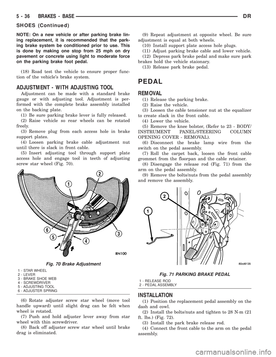
screw star wheel (Fig. 70).
(6) Rotate adjuster screw star wheel (move tool
handle upward) until slight drag can be felt when
wheel is rotated.
(7) Push and hold adjuster lever away from star
wheel with thin screwdriver.
(8) Back off adjuster screw star wheel until brake
drag is eliminated.(9) Repeat adjustment at opposite wheel. Be sure
adjustment is equal at both wheels.
(10) Install support plate access hole plugs.
(11) Adjust parking brake cable and lower vehicle.
(12) Depress park brake pedal and make sure park
brakes hold the vehicle staionary.
(13) Release park brake pedal.
PEDAL
REMOVAL
(1) Release the parking brake.
(2) Raise the vehicle.
(3) Loosen the cable tensioner nut at the equalizer
to create slack in the front cable.
(4) Lower the vehicle.
(5) Remove the knee bolster, (Refer to 23 - BODY/
INSTRUMENT PANEL/STEERING COLUMN
OPENING COVER - REMOVAL).
(6) Disconnect the brake lamp wire from the
switch on the pedal assembly.
(7) Roll the carpet back, loosen the front cable
grommet from the floorpan and the cable retainer.
(8) Disengage the release rod (Fig. 71) from the
arm on the pedal assembly.
(9) Remove the bolts/nuts from the pedal assembly
and remove the assembly.
INSTALLATION
(1) Position the replacement pedal assembly on the
dash and cowl.
(2) Install the bolts/nuts and tighten to 28 N´m (21
ft. lbs.) (Fig. 72).
(3) Install the park brake release rod.
(4) Connect the front cable to the arm on the pedal
assembly.
Fig. 70 Brake Adjustment
1 - STAR WHEEL
2 - LEVER
3 - BRAKE SHOE WEB
4 - SCREWDRIVER
5 - ADJUSTING TOOL
6 - ADJUSTER SPRINGFig. 71 PARKING BRAKE PEDAL
1 - RELEASE ROD
2 - PEDAL ASSEMBLY
5 - 36 BRAKES - BASEDR
SHOES (Continued)
Page 274 of 2895

CLUTCH
TABLE OF CONTENTS
page page
CLUTCH
DESCRIPTION..........................1
OPERATION............................1
WARNING.............................2
DIAGNOSIS AND TESTING................2
SPECIFICATIONS........................6
CLUTCH DISC
REMOVAL.............................6
INSTALLATION..........................6
CLUTCH HOUSING
DIAGNOSIS AND TESTING................8
REMOVAL.............................10
INSTALLATION.........................10
CLUTCH RELEASE BEARING
REMOVAL.............................11
INSTALLATION.........................11FLYWHEEL
DIAGNOSIS AND TESTING................11
REMOVAL.............................12
DISASSEMBLY.........................12
ASSEMBLY............................12
INSTALLATION.........................12
PILOT BEARING
REMOVAL.............................12
INSTALLATION.........................12
LINKAGE
REMOVAL.............................13
INSTALLATION.........................13
CLUTCH PEDAL POSITION SWITCH
DESCRIPTION.........................14
OPERATION...........................14
DIAGNOSIS AND TESTING................14
CLUTCH
DESCRIPTION
The clutch mechanism consists of a flywheel, a sin-
gle, dry-type disc, and a diaphragm style clutch cover
(Fig. 1). A hydraulic linkage is used to operate the
clutch release bearing and fork. The flywheel is
bolted to the rear flange of the crankshaft. The
clutch pressure plate is bolted to the flywheel with
the clutch disc located between these two compo-
nents. The clutch system provides the mechanical,
but still easily detachable, link between the engine
and the transmission. The system is designed to
ensure that the full torque output of the engine is
transfered to the transmission while isolating the
transmission from the engine firing pulses to mini-
mize concerns such as gear rattle.
OPERATION
Leverage, clamping force and friction are what
make the clutch work. The disc serves as the friction
element and a diaphragm spring and pressure plate
provide the clamping force. The clutch pedal, hydrau-
lic linkage, release lever and bearing provide the
leverage.
The clutch master cylinder push rod is connected
to the clutch pedal. When the clutch pedal is
depressed, the slave cylinder is operated by the
clutch master cylinder mounted on the dash panel.
The release fork is actuated by the hydraulic slave
cylinder mounted on the transmission housing. Therelease bearing is operated by a release fork pivoting
on a ball stud mounted in the transmission housing.
The release bearing then depresses the pressure
plate spring fingers, releasing pressure on the clutch
disc and allowing the engine crankshaft to spin inde-
pendently of the transmission input shaft (Fig. 2).
Fig. 1 ENGINE POWERFLOW
DRCLUTCH 6 - 1
Page 286 of 2895

(3) Install clutch disc, pressure plate and trans-
mission.
LINKAGE
REMOVAL
CAUTION: The hydraulic linkage has a quick dis-
connect at the slave cylinder. This fitting should
never be disconnected or tampered with. Once the
hydraulic line is connected to the slave cylinder, it
should never be disconnected.
(1) Raise and support vehicle.
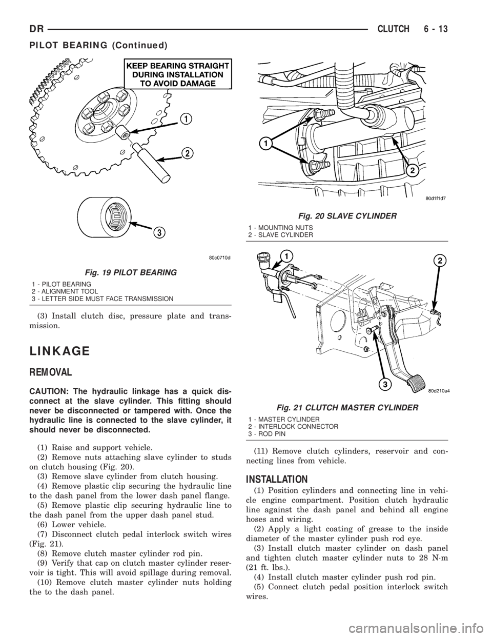
(2) Remove nuts attaching slave cylinder to studs
on clutch housing (Fig. 20).
(3) Remove slave cylinder from clutch housing.
(4) Remove plastic clip securing the hydraulic line
to the dash panel from the lower dash panel flange.
(5) Remove plastic clip securing hydraulic line to
the dash panel from the upper dash panel stud.
(6) Lower vehicle.
(7) Disconnect clutch pedal interlock switch wires
(Fig. 21).
(8) Remove clutch master cylinder rod pin.
(9) Verify that cap on clutch master cylinder reser-
voir is tight. This will avoid spillage during removal.
(10) Remove clutch master cylinder nuts holding
the to the dash panel.(11) Remove clutch cylinders, reservoir and con-
necting lines from vehicle.
INSTALLATION
(1) Position cylinders and connecting line in vehi-
cle engine compartment. Position clutch hydraulic
line against the dash panel and behind all engine
hoses and wiring.
(2) Apply a light coating of grease to the inside
diameter of the master cylinder push rod eye.
(3) Install clutch master cylinder on dash panel
and tighten clutch master cylinder nuts to 28 N´m
(21 ft. lbs.).
(4) Install clutch master cylinder push rod pin.
(5) Connect clutch pedal position interlock switch
wires.
Fig. 19 PILOT BEARING
1 - PILOT BEARING
2 - ALIGNMENT TOOL
3 - LETTER SIDE MUST FACE TRANSMISSION
Fig. 20 SLAVE CYLINDER
1 - MOUNTING NUTS
2 - SLAVE CYLINDER
Fig. 21 CLUTCH MASTER CYLINDER
1 - MASTER CYLINDER
2 - INTERLOCK CONNECTOR
3 - ROD PIN
DRCLUTCH 6 - 13
PILOT BEARING (Continued)
Page 294 of 2895

WARNING: DO NOT REMOVE CYLINDER BLOCK
DRAIN PLUGS OR LOOSEN RADIATOR DRAIN-
COCK WITH SYSTEM HOT AND UNDER PRESSURE.
SERIOUS BURNS FROM COOLANT CAN OCCUR.
Drain sufficient coolant to allow thermostat
removal. (Refer to 7 - COOLING/ENGINE/ENGINE
COOLANT THERMOSTAT - REMOVAL). Remove
accessory drive belt (Refer to 7 - COOLING/ACCES-
SORY DRIVE/DRIVE BELTS - REMOVAL).
Add coolant to radiator to bring level to within 6.3
mm (1/4 in) of the top of the thermostat housing.CAUTION: Avoid overheating. Do not operate
engine for an excessive period of time. Open drain-
cock immediately after test to eliminate boil over.
Start engine and accelerate rapidly three times, to
approximately 3000 rpm while observing coolant. If
internal engine combustion gases are leaking into
cooling system, bubbles will appear in coolant. If bub-
bles do not appear, internal combustion gas leakage
is not present.
DIAGNOSIS AND TESTING - COOLING SYSTEM
DIESEL ENGINE
COOLING SYSTEM DIAGNOSISÐDIESEL ENGINE
CONDITION POSSIBLE CAUSES CORRECTION
TEMPERATURE GAUGE READS
LOWNOTE:
Information on dash cluster is
displayed based on broadcast data
from ECM. DTC will be set for
engine sensor circuit concern.1. Vehicle is equipped with a heavy
duty cooling system.1. None. System operating normally.
2. Thermostat stuck open 2. Inspect and test thermostat.
3. Coolant level low. 3. Fill cooling system. (Refer to 7 -
COOLING - STANDARD
PROCEDURE)
4. Temperature gauge not
functioning correctly.4. Check cluster (Refer to 8 -
ELECTRICAL/INSTRUMENT
CLUSTER - DIAGNOSIS AND
TESTING)
DRCOOLING 7 - 7
COOLING (Continued)
Page 393 of 2895

²supplies a reference voltage for the Throttle
Position Sensor (TPS) sensor.
Secondary 5±volt supply:
²supplies the required 5 volt power source to the
oil pressure sensor.
²supplies the required 5 volt power source for the
Vehicle Speed Sensor (VSS) (if equipped).
²supplies the 5 volt power source to the transmis-
sion pressure sensor (certain automatic transmis-
sions).
OPERATION - IGNITION CIRCUIT SENSE
The ignition circuit sense input tells the PCM the
ignition switch has energized the ignition circuit.
Battery voltage is also supplied to the PCM
through the ignition switch when the ignition is in
the RUN or START position. This is referred to as
the9ignition sense9circuit and is used to9wake up9
the PCM. Voltage on the ignition input can be as low
as 6 volts and the PCM will still function. Voltage is
supplied to this circuit to power the PCM's 8-volt reg-
ulator and to allow the PCM to perform fuel, ignition
and emissions control functions.
REMOVAL
USE THE DRB SCAN TOOL TO REPROGRAM
THE NEW POWERTRAIN CONTROL MODULE
(PCM) WITH THE VEHICLES ORIGINAL IDEN-
TIFICATION NUMBER (VIN) AND THE VEHI-
CLES ORIGINAL MILEAGE. IF THIS STEP IS
NOT DONE, A DIAGNOSTIC TROUBLE CODE
(DTC) MAY BE SET.
The PCM is located in the engine compartment
attached to the dash panel (Fig. 6).
To avoid possible voltage spike damage to the
PCM, ignition key must be off, and negative battery
cable must be disconnected before unplugging PCM
connectors.
(1) Disconnect negative battery cable at battery.
(2) Remove cover over electrical connectors. Cover
snaps onto PCM.
(3) Carefully unplug the three 32±way connectors
(four 38±way connectors if equipped with NGC) from
PCM (Fig. 7).
(4) Remove three PCM mounting bolts (Fig. 7) and
remove PCM from vehicle.
INSTALLATION
USE THE DRB SCAN TOOL TO REPROGRAM
THE NEW POWERTRAIN CONTROL MODULE
(PCM) WITH THE VEHICLES ORIGINAL IDEN-
TIFICATION NUMBER (VIN) AND THE VEHI-
CLES ORIGINAL MILEAGE. IF THIS STEP IS
NOT DONE, A DIAGNOSTIC TROUBLE CODE
(DTC) MAY BE SET.
(1) Install PCM and 3 mounting bolts to vehicle.
Fig. 6 PCM LOCATION
1 - COWL GRILL
2 - PCM
3 - COWL (RIGHT-REAR)
Fig. 7 PCM REMOVAL / INSTALLATION
1 - THREE 32-WAY CONNECTORS WITH JTEC (FOUR 38-WAY
CONNECTORS WITH NGC)
2 - PCM MOUNTING BRACKET
3 - PCM
4 - PCM MOUNTING SCREWS (3)
8E - 12 ELECTRONIC CONTROL MODULESDR
POWERTRAIN CONTROL MODULE (Continued)
Page 474 of 2895

REMOVAL
CAUTION: Base ignition timing is not adjustable on
any engine. Distributors do not have built in centrif-
ugal or vacuum assisted advance. Base ignition
timing and timing advance are controlled by the
Powertrain Control Module (PCM). Because a con-
ventional timing light can not be used to adjust dis-
tributor position after installation, note position of
distributor before removal.
(1) Disconnect negative cable from battery.
(2) Remove air cleaner tubing.
(3) Remove distributor cap from distributor (two
screws).
(4) Mark the position of distributor housing in
relationship to engine or dash panel. This is done to
aid in installation.
(5) Before distributor is removed, the number one
cylinder must be brought to the Top Dead Center
(TDC) firing position.
(6) Attach a socket to the Crankshaft Vibration
Damper mounting bolt.
(7) Slowly rotate engine clockwise, as viewed from
front, until indicating mark on crankshaft vibration
damper is aligned to 0 degree (TDC) mark on timing
chain cover (Fig. 24).
(8) The distributor rotor should now be aligned to
the CYL. NO. 1 alignment mark (stamped) into the
camshaft position sensor (Fig. 25). If not, rotate the
crankshaft through another complete 360 degree
turn. Note the position of the number one cylinder
spark plug cable (on the cap) in relation to rotor.
Rotor should now be aligned to this position.(9) Disconnect camshaft position sensor wiring
harness from main engine wiring harness.
(10) Remove distributor rotor from distributor
shaft.
(11) Remove distributor holddown clamp bolt and
clamp (Fig. 26). Remove distributor from vehicle.
CAUTION: Do not crank engine with distributor
removed. Distributor/crankshaft relationship will be
lost.
Fig. 24 DAMPER-TO-COVER ALIGNMENT MARKS Ð
TYPICAL
1 - ALIGNMENT MARK
2 - TIMING CHAIN COVER MARKS
3 - CRANKSHAFT VIBRATION DAMPER
Fig. 25 ROTOR ALIGNMENT MARK
1 - CAMSHAFT POSITION SENSOR ALIGNMENT MARK
2 - ROTOR
3 - DISTRIBUTOR
Fig. 26 DISTRIBUTOR HOLDDOWN CLAMP
1 - CLAMP BOLT
2 - HOLDDOWN CLAMP
3 - DISTRIBUTOR HOUSING
DRIGNITION CONTROL 8I - 17
DISTRIBUTOR (Continued)
Page 551 of 2895

HEADLAMP SWITCH
DESCRIPTION
The multiplexed headlamp switch is located on the
instrument panel. The headlamp switch controls the
parking lamps, fog lamps and the headlamps. A sep-
arate switch in the module controls the interior
lamps and instrument cluster illumination. This
switch also contains a rheostat for controlling the
illumination level of the cluster lamps.
OPERATION
The multiplexed headlamp switch has an off, park-
ing lamp, fog lamp and a headlamp on position. High
beams are controlled by the multiplexed multifunc-
tion switch on the steering column. The fog lamps
are illuminated by pulling back on the headlamp
switch knob when in the parking lamp or headlamp
ON position.The headlamp switch cannot be
repaired. It must be replaced.
The Instrument Cluster monitors the headlamp
and multifunction switch operation. When the head-
lamp switch is rotated to the parking lamp or On
position the Instrument Cluster sends a J1850 mes-
sage to the Front Control Module, which is mated to
the power distribution center to become the Inte-
grated Control Module, to illuminate the appropriate
bulbs. When the multifunction switch is activated to
the optical horn or high beam position the Instru-
ment Cluster illuminates the high beam indicator
and sends a J1850 message to the Front Control
Module to illuminate the appropriate bulbs.
REMOVAL
WARNING: ON VEHICLES EQUIPPED WITH AIR-
BAGS, DISABLE THE AIRBAG SYSTEM BEFORE
ATTEMPTING ANY STEERING WHEEL, STEERING
COLUMN, OR INSTRUMENT PANEL COMPONENT
DIAGNOSIS OR SERVICE. DISCONNECT AND ISO-
LATE THE BATTERY NEGATIVE (GROUND) CABLE,
THEN WAIT TWO MINUTES FOR THE AIRBAG SYS-
TEM CAPACITOR TO DISCHARGE BEFORE PER-
FORMING FURTHER DIAGNOSIS OR SERVICE. THIS
IS THE ONLY SURE WAY TO DISABLE THE AIRBAG
SYSTEM. FAILURE TO TAKE THE PROPER PRE-
CAUTIONS COULD RESULT IN ACCIDENTAL AIR-
BAG DEPLOYMENT AND POSSIBLE PERSONAL
INJURY.
(1) Disconnect and isolate the battery negative
cable.
(2) Remove the left instrument panel bezel. (Refer
to 23 - BODY/INSTRUMENT PANEL/CLUSTER
BEZEL - REMOVAL).
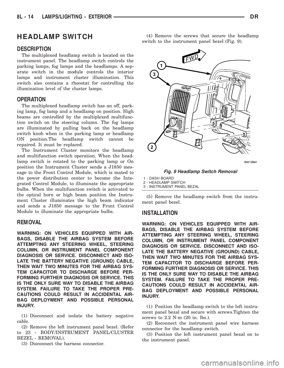
(3) Disconnect the harness connector.(4) Remove the screws that secure the headlamp
switch to the instrument panel bezel (Fig. 9).
(5) Remove the headlamp switch from the instru-
ment panel bezel.
INSTALLATION
WARNING: ON VEHICLES EQUIPPED WITH AIR-
BAGS, DISABLE THE AIRBAG SYSTEM BEFORE
ATTEMPTING ANY STEERING WHEEL, STEERING
COLUMN, OR INSTRUMENT PANEL COMPONENT
DIAGNOSIS OR SERVICE. DISCONNECT AND ISO-
LATE THE BATTERY NEGATIVE (GROUND) CABLE,
THEN WAIT TWO MINUTES FOR THE AIRBAG SYS-
TEM CAPACITOR TO DISCHARGE BEFORE PER-
FORMING FURTHER DIAGNOSIS OR SERVICE. THIS
IS THE ONLY SURE WAY TO DISABLE THE AIRBAG
SYSTEM. FAILURE TO TAKE THE PROPER PRE-
CAUTIONS COULD RESULT IN ACCIDENTAL AIR-
BAG DEPLOYMENT AND POSSIBLE PERSONAL
INJURY.
(1) Position the headlamp switch to the left instru-
ment panel bezal and secure with screws.Tighten the
screws to 2.2 N´m (20 in. lbs.).
(2) Reconnect the instrument panel wire harness
connector for the headlamp switch.
(3) Position the left instrument panel bezal on to
the instrument panel.
Fig. 9 Headlamp Switch Removal
1 - DASH BOARD
2 - HEADLAMP SWITCH
3 - INSTRUMENT PANEL BEZAL
8L - 14 LAMPS/LIGHTING - EXTERIORDR
Page 562 of 2895

DOOR AJAR SWITCH
DESCRIPTION
The door ajar switches are integral to the door
latches on each door. The switches close a path to
ground for the Instrument Cluster when a door is
opened.
The door ajar switches cannot be repaired and, if
faulty or damaged, the door latch unit must be
replaced. Refer to the Body section under Doors for
the removal and installation procedure.
OPERATION
The door ajar switches close a path to ground for
the Instrument Cluster when a door is opened. The
passenger front door is connected in a parallel-series
circuit between ground and the Instrument Cluster,
while the driver side front door ajar switch is con-
nected in series between ground and the Instrument
Cluster to provide a unique input. The Instrument
Cluster reads the switch status, then sends the
proper switch status messages to other electronic
modules over the Programmable Communications
Interface (PCI) data bus network. The door ajar
switches can be diagnosed using conventional diag-
nostic tools and methods. Refer to the Body section
under Doors for the Removal and Installation proce-
dures.
GLOVE BOX LAMP/SWITCH
REMOVAL
(1) Disconnect and isolate the battery negative
cable.
(2) Remove the glove box from the instrument
panel. (Refer to 23 - BODY/INSTRUMENT PANEL/
GLOVE BOX - REMOVAL) for the procedures.(3) Reach through the glove box opening and
behind the glove box lamp and switch mounting
bracket to access the instrument panel wire harness
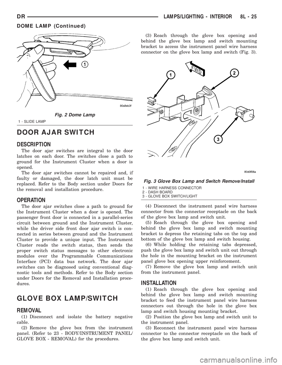
connector on the glove box lamp and switch (Fig. 3).
(4) Disconnect the instrument panel wire harness
connector from the connector receptacle on the back
of the glove box lamp and switch unit.
(5) Reach through the glove box opening and
behind the glove box lamp and switch mounting
bracket to depress the retaining tabs on the top and
bottom of the glove box lamp and switch housing.
(6) While holding the retaining tabs depressed,
push the glove box lamp and switch unit out through
the hole in the mounting bracket on the instrument
panel glove box opening upper reinforcement.
(7) Remove the glove box lamp and switch unit
from the instrument panel.
INSTALLATION
(1) Reach through the glove box opening and
behind the glove box lamp and switch mounting
bracket to feed the instrument panel wire harness
connectors out through the hole in the glove box
lamp and switch housing mounting bracket.
(2) Position the glove box lamp and switch unit to
the instrument panel.
(3) Reconnect the instrument panel wire harness
connector to the connector receptacle on the back of
the glove box lamp and switch unit.
Fig. 2 Dome Lamp
1 - SLIDE LAMP
Fig. 3 Glove Box Lamp and Switch Remove/Install
1 - WIRE HARNESS CONNECTOR
2 - DASH BOARD
3 - GLOVE BOX SWITCH/LIGHT
DRLAMPS/LIGHTING - INTERIOR 8L - 25
DOME LAMP (Continued)