2003 DODGE RAM Dash removal
[x] Cancel search: Dash removalPage 2800 of 2895
(1) Recover refrigerant(Refer to 24 - HEATING &
AIR CONDITIONING/PLUMBING - STANDARD
PROCEDURE).
(2) Remove and disassemble the HVAC housing.
(Refer to 24 - HEATING & AIR CONDITIONING/
DISTRIBUTION/HVAC HOUSING - REMOVAL)
(Refer to 24 - HEATING & AIR CONDITIONING/
DISTRIBUTION/HVAC HOUSING - DISASSEMBLY)
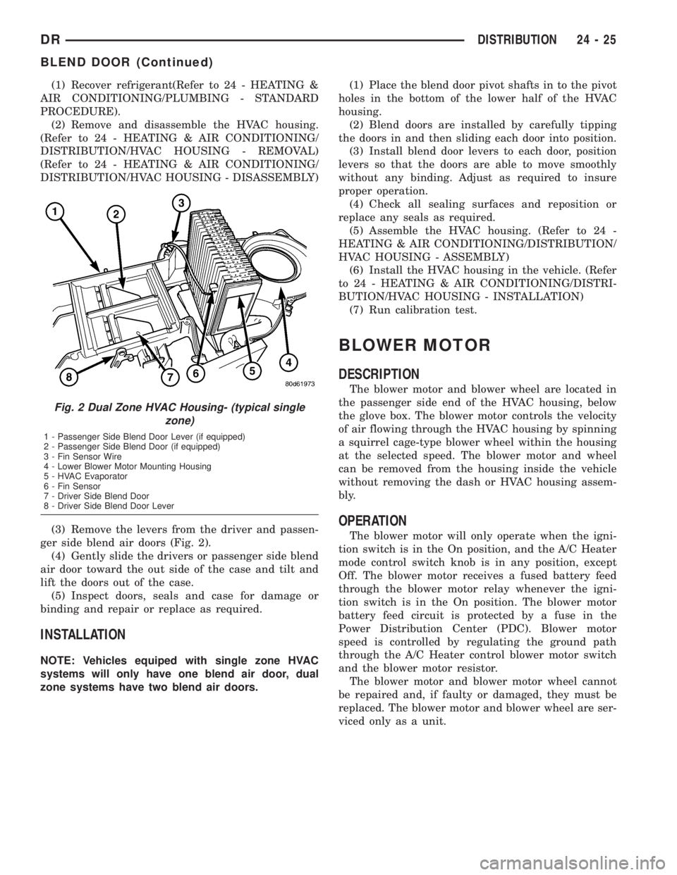
(3) Remove the levers from the driver and passen-
ger side blend air doors (Fig. 2).
(4) Gently slide the drivers or passenger side blend
air door toward the out side of the case and tilt and
lift the doors out of the case.
(5) Inspect doors, seals and case for damage or
binding and repair or replace as required.
INSTALLATION
NOTE: Vehicles equiped with single zone HVAC
systems will only have one blend air door, dual
zone systems have two blend air doors.(1) Place the blend door pivot shafts in to the pivot
holes in the bottom of the lower half of the HVAC
housing.
(2) Blend doors are installed by carefully tipping
the doors in and then sliding each door into position.
(3) Install blend door levers to each door, position
levers so that the doors are able to move smoothly
without any binding. Adjust as required to insure
proper operation.
(4) Check all sealing surfaces and reposition or
replace any seals as required.
(5) Assemble the HVAC housing. (Refer to 24 -
HEATING & AIR CONDITIONING/DISTRIBUTION/
HVAC HOUSING - ASSEMBLY)
(6) Install the HVAC housing in the vehicle. (Refer
to 24 - HEATING & AIR CONDITIONING/DISTRI-
BUTION/HVAC HOUSING - INSTALLATION)
(7) Run calibration test.
BLOWER MOTOR
DESCRIPTION
The blower motor and blower wheel are located in
the passenger side end of the HVAC housing, below
the glove box. The blower motor controls the velocity
of air flowing through the HVAC housing by spinning
a squirrel cage-type blower wheel within the housing
at the selected speed. The blower motor and wheel
can be removed from the housing inside the vehicle
without removing the dash or HVAC housing assem-
bly.
OPERATION
The blower motor will only operate when the igni-
tion switch is in the On position, and the A/C Heater
mode control switch knob is in any position, except
Off. The blower motor receives a fused battery feed
through the blower motor relay whenever the igni-
tion switch is in the On position. The blower motor
battery feed circuit is protected by a fuse in the
Power Distribution Center (PDC). Blower motor
speed is controlled by regulating the ground path
through the A/C Heater control blower motor switch
and the blower motor resistor.
The blower motor and blower motor wheel cannot
be repaired and, if faulty or damaged, they must be
replaced. The blower motor and blower wheel are ser-
viced only as a unit.
Fig. 2 Dual Zone HVAC Housing- (typical single
zone)
1 - Passenger Side Blend Door Lever (if equipped)
2 - Passenger Side Blend Door (if equipped)
3 - Fin Sensor Wire
4 - Lower Blower Motor Mounting Housing
5 - HVAC Evaporator
6 - Fin Sensor
7 - Driver Side Blend Door
8 - Driver Side Blend Door Lever
DRDISTRIBUTION 24 - 25
BLEND DOOR (Continued)
Page 2801 of 2895
DIAGNOSIS AND TESTING - BLOWER MOTOR
WARNING: ON VEHICLES EQUIPPED WITH AIR-
BAGS, DISABLE THE AIRBAG SYSTEM BEFORE
ATTEMPTING ANY STEERING WHEEL, STEERING
COLUMN, OR INSTRUMENT PANEL COMPONENT
DIAGNOSIS OR SERVICE. DISCONNECT AND ISO-
LATE THE BATTERY NEGATIVE (GROUND) CABLE,
THEN WAIT TWO MINUTES FOR THE AIRBAG SYS-
TEM CAPACITOR TO DISCHARGE BEFORE PER-
FORMING FURTHER DIAGNOSIS OR SERVICE. THIS
IS THE ONLY SURE WAY TO DISABLE THE AIRBAG
SYSTEM. FAILURE TO TAKE THE PROPER PRE-
CAUTIONS COULD RESULT IN AN ACCIDENTAL
AIRBAG DEPLOYMENT AND POSSIBLE PERSONAL
INJURY.
For circuit descriptions and diagrams, (Refer to
Appropriate Wiring Information). Possible causes of
an inoperative blower motor include:
²Faulty fuse
²Faulty blower motor circuit wiring or wire har-
ness connectors
²Faulty blower motor resistor
²Faulty blower motor relay
²Faulty blower motor switch
²Faulty A/C Heater mode control switch
²Faulty blower motor.
Possible causes of the blower motor not operating
in all speeds include:
²Faulty blower motor switch
²Faulty blower motor resistor
²Faulty blower motor circuit wiring or wire har-
ness connectors.
VIBRATION
Possible causes of blower motor vibration include:
²Improper blower motor mounting
²Improper blower wheel mounting
²Blower wheel out of balance or bent
²Blower motor faulty.
NOISE
To verify that the blower is the source of the noise,
unplug the blower motor wire harness connector and
operate the HVAC system. If the noise goes away,
possible causes include:
²Foreign material in the HVAC housing
²Improper blower motor mounting
²Improper blower wheel mounting
²Blower motor faulty.
REMOVAL
WARNING: ON VEHICLES EQUIPPED WITH AIR-
BAGS, DISABLE THE AIRBAG SYSTEM BEFORE
ATTEMPTING ANY STEERING WHEEL, STEERINGCOLUMN, OR INSTRUMENT PANEL COMPONENT
DIAGNOSIS OR SERVICE. DISCONNECT AND ISO-
LATE THE BATTERY NEGATIVE (GROUND) CABLE,
THEN WAIT TWO MINUTES FOR THE AIRBAG SYS-
TEM CAPACITOR TO DISCHARGE BEFORE PER-
FORMING FURTHER DIAGNOSIS OR SERVICE. THIS
IS THE ONLY SURE WAY TO DISABLE THE AIRBAG
SYSTEM. FAILURE TO TAKE THE PROPER PRE-
CAUTIONS COULD RESULT IN AN ACCIDENTAL
AIRBAG DEPLOYMENT AND POSSIBLE PERSONAL
INJURY.
The blower motor is located on the passenger side
of the vehicle under the dash
(1) Disconnect and isolate the battery negative
cable.
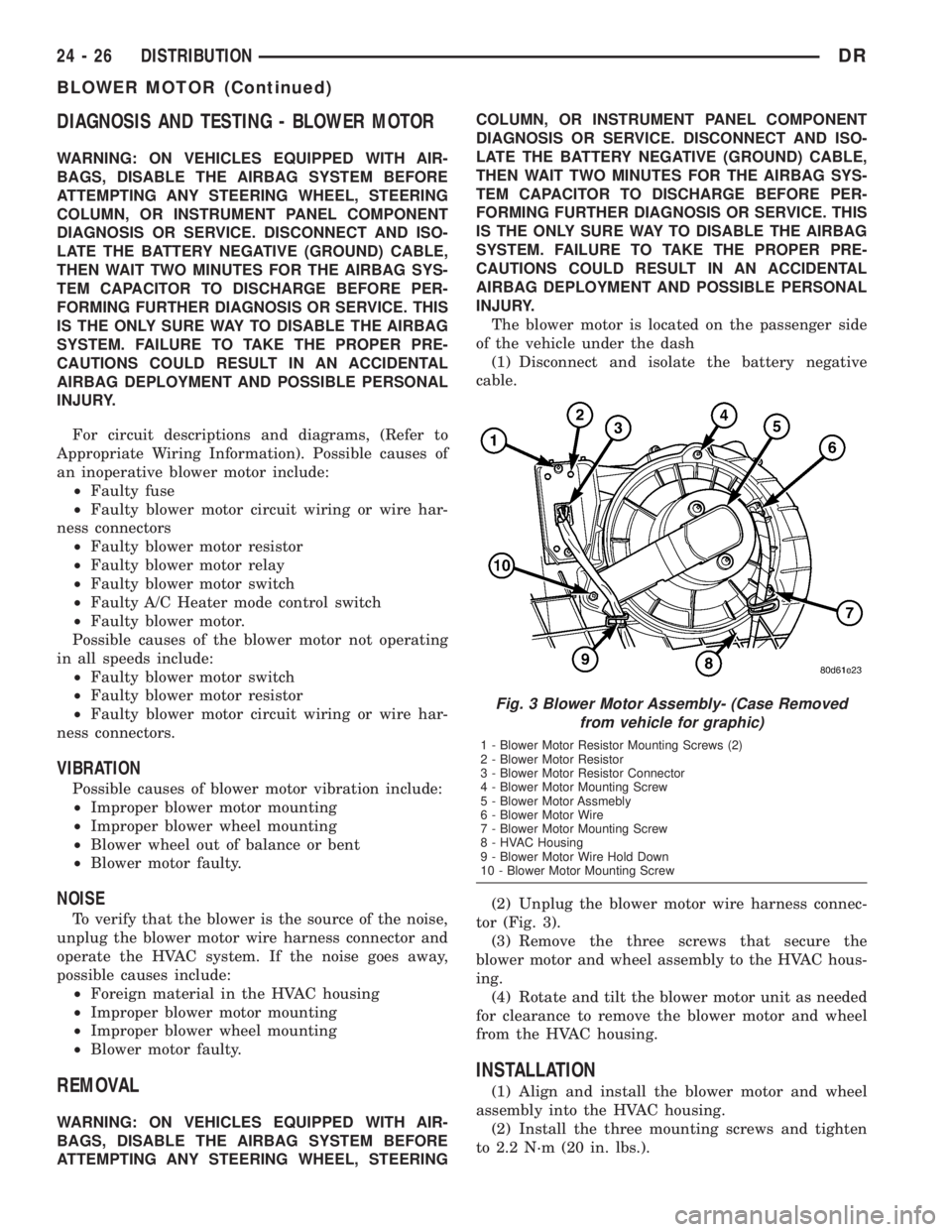
(2) Unplug the blower motor wire harness connec-
tor (Fig. 3).
(3) Remove the three screws that secure the
blower motor and wheel assembly to the HVAC hous-
ing.
(4) Rotate and tilt the blower motor unit as needed
for clearance to remove the blower motor and wheel
from the HVAC housing.
INSTALLATION
(1) Align and install the blower motor and wheel
assembly into the HVAC housing.
(2) Install the three mounting screws and tighten
to 2.2 N´m (20 in. lbs.).
Fig. 3 Blower Motor Assembly- (Case Removed
from vehicle for graphic)
1 - Blower Motor Resistor Mounting Screws (2)
2 - Blower Motor Resistor
3 - Blower Motor Resistor Connector
4 - Blower Motor Mounting Screw
5 - Blower Motor Assmebly
6 - Blower Motor Wire
7 - Blower Motor Mounting Screw
8 - HVAC Housing
9 - Blower Motor Wire Hold Down
10 - Blower Motor Mounting Screw
24 - 26 DISTRIBUTIONDR
BLOWER MOTOR (Continued)
Page 2804 of 2895
(2) Install the screws and snap clips that secure
the upper and lower HVAC housing halves to each
other. Tighten the screws to 2.2 N´m (20 in. lbs.).
(3) Install the blower motor and wheel unit in the
HVAC housing. (Refer to 24 - HEATING & AIR CON-
DITIONING/DISTRIBUTION/BLOWER MOTOR -
INSTALLATION)
(4) Install the foam seals on the flanges around
the heater core and evaporator coil tube mounting
flange of the HVAC housing. Repair or replace any
seals as required.
(5) Install the electrical wiring harness for the
acutators. Make sure the wires are routed through
all wiring retainers, replace any retainers that are
damaged or missing.
(6) Connect the wiring harness to each actuator,
making sure each connector is securely attached.
INSTALLATION
WARNING: IF THE VEHICLE IS EQUIPPED WITH AIR
CONDITIONING, REVIEW THE WARNINGS AND
CAUTIONS IN PLUMBING BEFORE PERFORMING
THE FOLLOWING OPERATION. (Refer to 24 - HEAT-
ING & AIR CONDITIONING/PLUMBING - WARNING)
(Refer to 24 - HEATING & AIR CONDITIONING/
PLUMBING - CAUTION) (Refer to 24 - HEATING &
AIR CONDITIONING/PLUMBING - CAUTION -
REFRIGERANT HOSES/LINES/TUBES PRECAU-
TIONS)
(1) Position the HVAC housing to the dash panel.
Be certain that the evaporator condensate drain tube
and the housing mounting studs are inserted into
their correct mounting holes.
(2) Install and tighten the nuts onto the HVAC
housing mounting studs. Tighten the nuts to 6.2 N´m
(55 in.lbs.).
(3) Connect the HVAC system electrical connec-
tors.
(4) Unplug or remove the tape from the heater
core tubes. Connect the heater hoses to the heater
core tubes and fill the engine cooling system(Refer to
7 - COOLING/ENGINE - STANDARD PROCE-
DURE).
(5) Unplug or remove the tape from the liquid line
and the evaporator inlet tube fittings. Connect the
liquid line coupler to the evaporator inlet tube. (Refer
to 24 - HEATING & AIR CONDITIONING/PLUMB-
ING - STANDARD PROCEDURE - A/C LINE COU-
PLERS)(6) Evacuate the refrigerant system. (Refer to 24 -
HEATING & AIR CONDITIONING/PLUMBING -
STANDARD PROCEDURE - REFRIGERANT SYS-
TEM EVACUATE)
(7) Charge the refrigerant system. (Refer to 24 -
HEATING & AIR CONDITIONING/PLUMBING -
STANDARD PROCEDURE - REFRIGERANT SYS-
TEM CHARGE)
(8) Install the instrument panel in the vehicle(Re-
fer to 23 - BODY/INSTRUMENT PANEL - INSTAL-
LATION).
(9) Connect the battery negative cable.
(10) Start the engine and check for proper opera-
tion of the heating and air conditioning systems.
(11) Run the calibration procedure.
INSTRUMENT PANEL DUCTS
REMOVAL
(1) Disconnect and isolate the battery negative
cable.
(2) Remove the HVAC assembly from the vehi-
cle(Refer to 24 - HEATING & AIR CONDITIONING/
DISTRIBUTION/HVAC HOUSING - REMOVAL).
(3) Disasemble the HVAC housing(Refer to 24 -
HEATING & AIR CONDITIONING/DISTRIBUTION/
HVAC HOUSING - DISASSEMBLY).
(4) Remove the panel door actuator from the hous-
ing if not already removed.
(5) With the actuator removed you can take the
door and shift it so that one pivot point will clear the
housing. You can then tilt the door and remove it
from the housing.
INSTALLATION
(1) Take the door and tilt it so one pivot point is
installed. The carfully install the second pivot point.
Check to be sure no binding of the door is occuring,
repair as required.
(2) Reassemble the HVAC housing(Refer to 24 -
HEATING & AIR CONDITIONING/DISTRIBUTION/
HVAC HOUSING - ASSEMBLY).
(3) Install the HVAC assembly into the vehicle(Re-
fer to 24 - HEATING & AIR CONDITIONING/DIS-
TRIBUTION/INSTRUMENT PANEL DUCTS -
INSTALLATION).
(4) Connect the battery negative cable.
DRDISTRIBUTION 24 - 29
HVAC HOUSING (Continued)
Page 2820 of 2895
STANDARD PROCEDURE - REFRIGERANT SYS-
TEM EVACUATE)
(7) Charge the refrigerant system. (Refer to 24 -
HEATING & AIR CONDITIONING/PLUMBING -
STANDARD PROCEDURE - REFRIGERANT SYS-
TEM CHARGE)
LIQUID LINE
REMOVAL
WARNING: REVIEW THE WARNINGS AND CAU-
TIONS IN THE FRONT OF THIS SECTION BEFORE
PERFORMING THE FOLLOWING OPERATION.
(Refer to 24 - HEATING & AIR CONDITIONING/
PLUMBING - WARNING) (Refer to 24 - HEATING &
AIR CONDITIONING/PLUMBING - CAUTION)
(1) Disconnect and isolate the battery negative
cable.
NOTE: Removal of the second battery and battery
tray is required on the diesel equipped vehicles.
(2) Remove rightside battery(Refer to 8 - ELEC-
TRICAL/BATTERY SYSTEM/BATTERY - REMOV-
AL).
(3) Remove rightside battery tray(Refer to 8 -
ELECTRICAL/BATTERY SYSTEM/TRAY - REMOV-
AL).
(4) Recover the refrigerant from the refrigerant
system. (Refer to 24 - HEATING & AIR CONDI-
TIONING/PLUMBING - STANDARD PROCEDURE -
REFRIGERANT RECOVERY)
(5) Disconnect the liquid line refrigerant line cou-
plers at the condenser outlet the mid point connec-
tion and the evaporator inlet. (Refer to 24 -
HEATING & AIR CONDITIONING/PLUMBING -
STANDARD PROCEDURE - A/C LINE COUPLERS)
Install plugs in, or tape over all of the opened refrig-
erant line fittings.
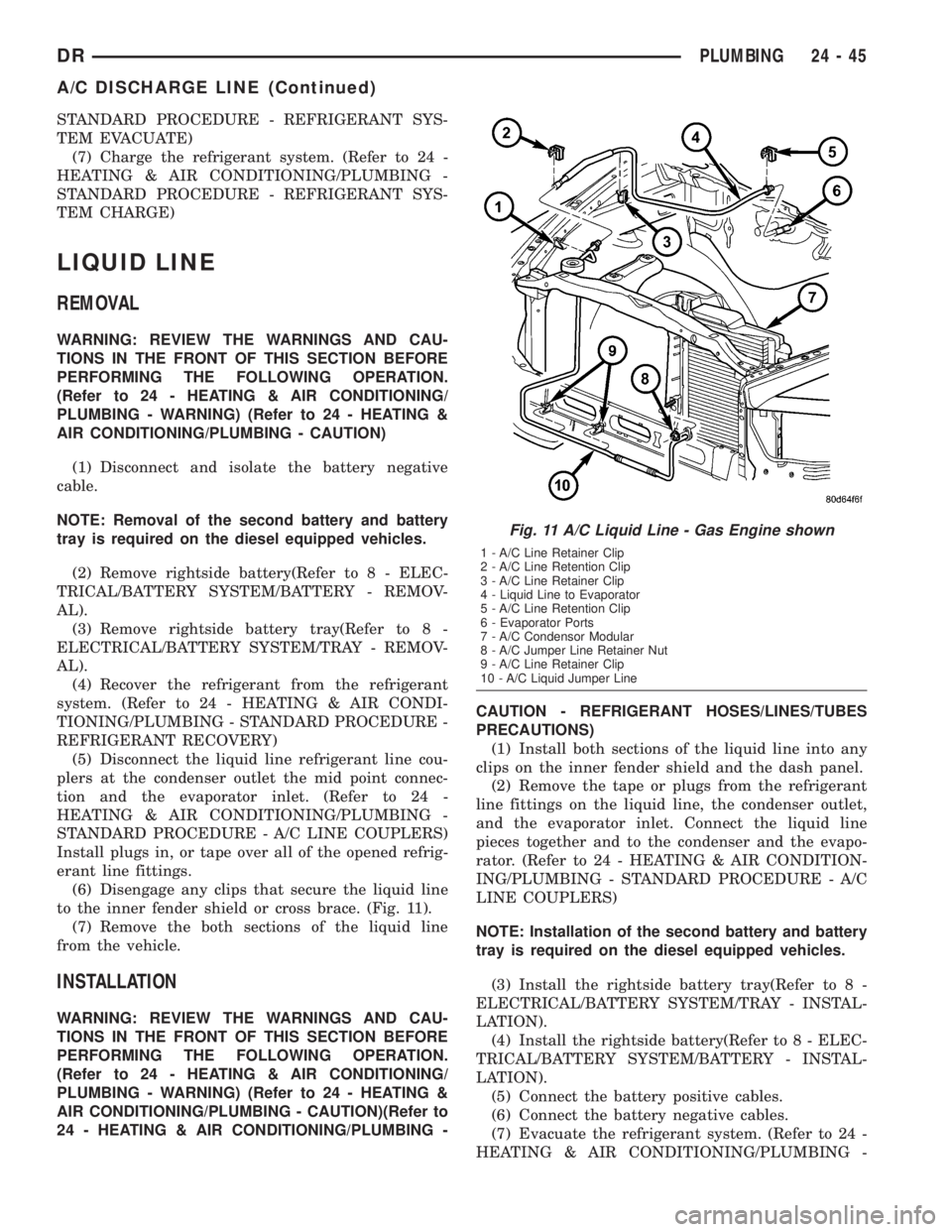
(6) Disengage any clips that secure the liquid line
to the inner fender shield or cross brace. (Fig. 11).
(7) Remove the both sections of the liquid line
from the vehicle.
INSTALLATION
WARNING: REVIEW THE WARNINGS AND CAU-
TIONS IN THE FRONT OF THIS SECTION BEFORE
PERFORMING THE FOLLOWING OPERATION.
(Refer to 24 - HEATING & AIR CONDITIONING/
PLUMBING - WARNING) (Refer to 24 - HEATING &
AIR CONDITIONING/PLUMBING - CAUTION)(Refer to
24 - HEATING & AIR CONDITIONING/PLUMBING -CAUTION - REFRIGERANT HOSES/LINES/TUBES
PRECAUTIONS)
(1) Install both sections of the liquid line into any
clips on the inner fender shield and the dash panel.
(2) Remove the tape or plugs from the refrigerant
line fittings on the liquid line, the condenser outlet,
and the evaporator inlet. Connect the liquid line
pieces together and to the condenser and the evapo-
rator. (Refer to 24 - HEATING & AIR CONDITION-
ING/PLUMBING - STANDARD PROCEDURE - A/C
LINE COUPLERS)
NOTE: Installation of the second battery and battery
tray is required on the diesel equipped vehicles.
(3) Install the rightside battery tray(Refer to 8 -
ELECTRICAL/BATTERY SYSTEM/TRAY - INSTAL-
LATION).
(4) Install the rightside battery(Refer to 8 - ELEC-
TRICAL/BATTERY SYSTEM/BATTERY - INSTAL-
LATION).
(5) Connect the battery positive cables.
(6) Connect the battery negative cables.
(7) Evacuate the refrigerant system. (Refer to 24 -
HEATING & AIR CONDITIONING/PLUMBING -
Fig. 11 A/C Liquid Line - Gas Engine shown
1 - A/C Line Retainer Clip
2 - A/C Line Retention Clip
3 - A/C Line Retainer Clip
4 - Liquid Line to Evaporator
5 - A/C Line Retention Clip
6 - Evaporator Ports
7 - A/C Condensor Modular
8 - A/C Jumper Line Retainer Nut
9 - A/C Line Retainer Clip
10 - A/C Liquid Jumper Line
DRPLUMBING 24 - 45
A/C DISCHARGE LINE (Continued)
Page 2824 of 2895
compartment. The liquid line should be hot to the
touch.
(5) Touch the liquid line near the evaporator inlet
at the rear of the engine compartment. The liquid
line should be cold to the touch.
(6) If there is a distinct temperature differential
between the two ends of the liquid line, the orifice
tube is in good condition. If there is little or no
detectable temperature differential between the two
ends of the liquid line, the orifice tube is obstructed
or missing and the liquid line must be replaced.
REMOVAL
The fixed orifice tube is located in the liquid line,
between the condenser and the evaporator coil. The
orifice has filter screens on the inlet and outlet ends
of the tube body. If the fixed orifice tube is faulty or
plugged, the liquid line assembly must be replace-
d(Refer to 24 - HEATING & AIR CONDITIONING/
PLUMBING/LIQUID LINE - REMOVAL).
INSTALLATION
The fixed orifice tube is located in the liquid line,
between the condenser and the evaporator coil. The
orifice has filter screens on the inlet and outlet ends
of the tube body. If the fixed orifice tube is faulty or
plugged, the liquid line assembly must be replace-
d(Refer to 24 - HEATING & AIR CONDITIONING/
PLUMBING/LIQUID LINE - INSTALLATION).
ACCUMULATOR
DESCRIPTION
The accumulator is mounted in the engine com-
partment between the A/C evaporator outlet tube and
the compressor inlet.
OPERATION
Refrigerant enters the accumulator canister as a
low pressure vapor through the inlet tube. Any liq-
uid, oil-laden refrigerant falls to the bottom of the
canister, which acts as a separator. A desiccant bag is
mounted inside the accumulator canister to absorb
any moisture which may have entered and become
trapped within the refrigerant system.
REMOVAL
WARNING: REVIEW THE WARNINGS AND CAU-
TIONS IN THE FRONT OF THIS SECTION BEFORE
PERFORMING THE FOLLOWING OPERATION.
(Refer to 24 - HEATING & AIR CONDITIONING/
PLUMBING - WARNING) (Refer to 24 - HEATING &
AIR CONDITIONING/PLUMBING - CAUTION)(1) Disconnect and isolate the battery negative
cable.
(2) Recover the refrigerant from the refrigerant
system. (Refer to 24 - HEATING & AIR CONDI-
TIONING/PLUMBING - STANDARD PROCEDURE -
REFRIGERANT RECOVERY)
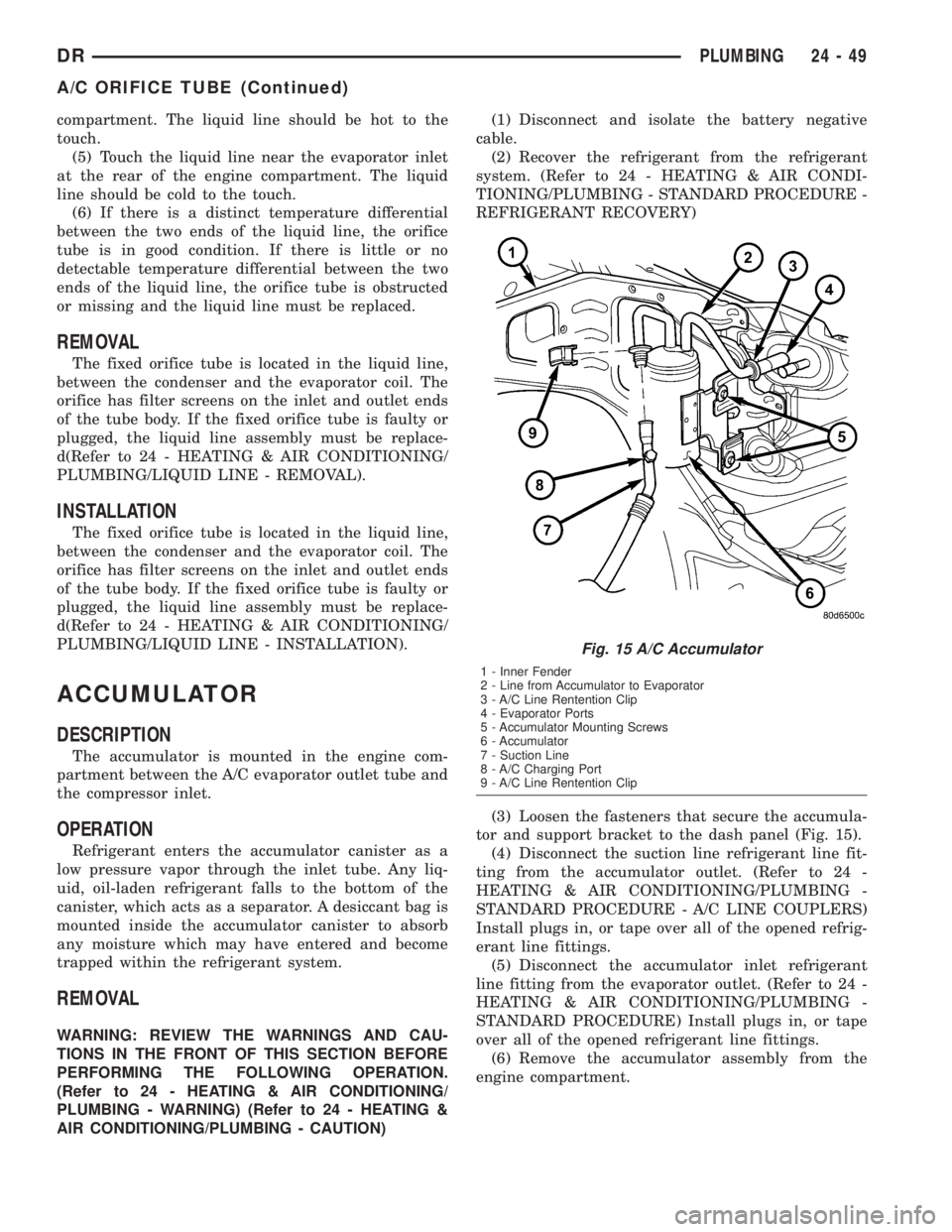
(3) Loosen the fasteners that secure the accumula-
tor and support bracket to the dash panel (Fig. 15).
(4) Disconnect the suction line refrigerant line fit-
ting from the accumulator outlet. (Refer to 24 -
HEATING & AIR CONDITIONING/PLUMBING -
STANDARD PROCEDURE - A/C LINE COUPLERS)
Install plugs in, or tape over all of the opened refrig-
erant line fittings.
(5) Disconnect the accumulator inlet refrigerant
line fitting from the evaporator outlet. (Refer to 24 -
HEATING & AIR CONDITIONING/PLUMBING -
STANDARD PROCEDURE) Install plugs in, or tape
over all of the opened refrigerant line fittings.
(6) Remove the accumulator assembly from the
engine compartment.
Fig. 15 A/C Accumulator
1 - Inner Fender
2 - Line from Accumulator to Evaporator
3 - A/C Line Rentention Clip
4 - Evaporator Ports
5 - Accumulator Mounting Screws
6 - Accumulator
7 - Suction Line
8 - A/C Charging Port
9 - A/C Line Rentention Clip
DRPLUMBING 24 - 49
A/C ORIFICE TUBE (Continued)