2003 DODGE RAM Dash removal
[x] Cancel search: Dash removalPage 1731 of 2895
The IAC motor has 4 wires with 4 circuits. Two of
the wires are for 12 volts and ground to supply elec-
trical current to the motor windings to operate the
stepper motor in one direction. The other 2 wires are
also for 12 volts and ground to supply electrical cur-
rent to operate the stepper motor in the opposite
direction.
To make the IAC go in the opposite direction, the
PCM just reverses polarity on both windings. If only
1 wire is open, the IAC can only be moved 1 step
(increment) in either direction. To keep the IAC
motor in position when no movement is needed, the
PCM will energize both windings at the same time.
This locks the IAC motor in place.
In the IAC motor system, the PCM will count
every step that the motor is moved. This allows the
PCM to determine the motor pintle position. If the
memory is cleared, the PCM no longer knows the
position of the pintle. So at the first key ON, the
PCM drives the IAC motor closed, regardless of
where it was before. This zeros the counter. From
this point the PCM will back out the IAC motor and
keep track of its position again.
When engine rpm is above idle speed, the IAC is
used for the following:
²Off-idle dashpot (throttle blade will close quickly
but idle speed will not stop quickly)
²Deceleration air flow control
²A/C compressor load control (also opens the pas-
sage slightly before the compressor is engaged so
that the engine rpm does not dip down when the
compressor engages)
²Power steering load control
The PCM can control polarity of the circuit to con-
trol direction of the stepper motor.
IAC Stepper Motor Program:The PCM is also
equipped with a memory program that records the
number of steps the IAC stepper motor most recently
advanced to during a certain set of parameters. For
example: The PCM was attempting to maintain a
1000 rpm target during a cold start-up cycle. The last
recorded number of steps for that may have been
125. That value would be recorded in the memory
cell so that the next time the PCM recognizes the
identical conditions, the PCM recalls that 125 steps
were required to maintain the target. This program
allows for greater customer satisfaction due to
greater control of engine idle.
Another function of the memory program, which
occurs when the power steering switch (if equipped),
or the A/C request circuit, requires that the IAC step-
per motor control engine rpm, is the recording of the
last targeted steps into the memory cell. The PCM
can anticipate A/C compressor loads. This is accom-
plished by delaying compressor operation for approx-
imately 0.5 seconds until the PCM moves the IACstepper motor to the recorded steps that were loaded
into the memory cell. Using this program helps elim-
inate idle-quality changes as loads change. Finally,
the PCM incorporates a9No-Load9engine speed lim-
iter of approximately 1800 - 2000 rpm, when it rec-
ognizes that the TPS is indicating an idle signal and
IAC motor cannot maintain engine idle.
A (factory adjusted) set screw is used to mechani-
cally limit the position of the throttle body throttle
plate.Never attempt to adjust the engine idle
speed using this screw.All idle speed functions are
controlled by the IAC motor through the PCM.
REMOVAL
3.7L V-6
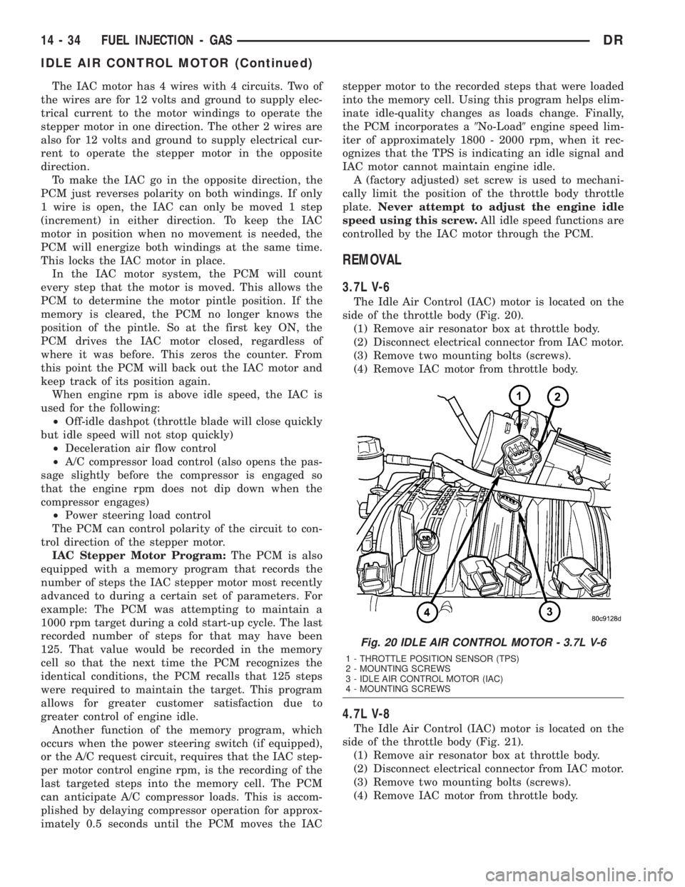
The Idle Air Control (IAC) motor is located on the
side of the throttle body (Fig. 20).
(1) Remove air resonator box at throttle body.
(2) Disconnect electrical connector from IAC motor.
(3) Remove two mounting bolts (screws).
(4) Remove IAC motor from throttle body.
4.7L V-8
The Idle Air Control (IAC) motor is located on the
side of the throttle body (Fig. 21).
(1) Remove air resonator box at throttle body.
(2) Disconnect electrical connector from IAC motor.
(3) Remove two mounting bolts (screws).
(4) Remove IAC motor from throttle body.
Fig. 20 IDLE AIR CONTROL MOTOR - 3.7L V-6
1 - THROTTLE POSITION SENSOR (TPS)
2 - MOUNTING SCREWS
3 - IDLE AIR CONTROL MOTOR (IAC)
4 - MOUNTING SCREWS
14 - 34 FUEL INJECTION - GASDR
IDLE AIR CONTROL MOTOR (Continued)
Page 1746 of 2895
THROTTLE CONTROL CABLE
REMOVAL
3.7L V-6
CAUTION: Be careful not to damage or kink cable
core wire (within cable sheathing) while servicing
accelerator pedal or throttle cable.
(1) From inside vehicle, hold up accelerator pedal.
Remove plastic cable retainer (clip) and throttle cable
core wire from upper end of pedal arm (Fig. 1). Plas-
tic cable retainer snaps into top of pedal arm.
(2) Remove cable core wire at pedal arm.
(3) From inside vehicle, remove metal clip holding
cable to dashpanel (Fig. 1).
(4) Remove air resonator box at throttle body.
(5) Unsnap cable from dashpanel routing clip.
(6) Remove cable housing from dash panel and
pull into engine compartment.
(7) Hold throttle in wide open position. While held
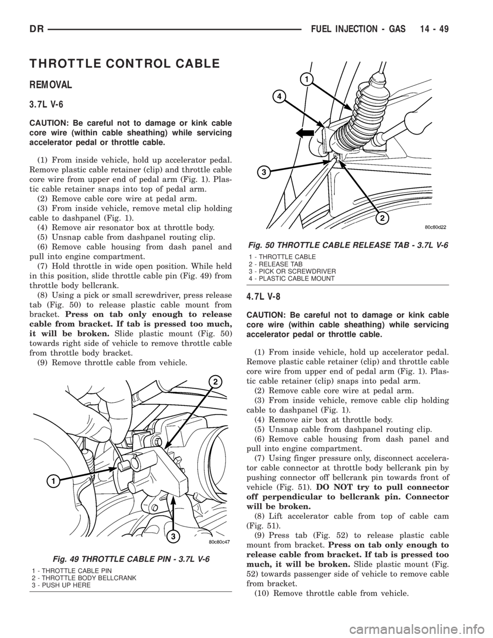
in this position, slide throttle cable pin (Fig. 49) from
throttle body bellcrank.
(8) Using a pick or small screwdriver, press release
tab (Fig. 50) to release plastic cable mount from
bracket.Press on tab only enough to release
cable from bracket. If tab is pressed too much,
it will be broken.Slide plastic mount (Fig. 50)
towards right side of vehicle to remove throttle cable
from throttle body bracket.
(9) Remove throttle cable from vehicle.
4.7L V-8
CAUTION: Be careful not to damage or kink cable
core wire (within cable sheathing) while servicing
accelerator pedal or throttle cable.
(1) From inside vehicle, hold up accelerator pedal.
Remove plastic cable retainer (clip) and throttle cable
core wire from upper end of pedal arm (Fig. 1). Plas-
tic cable retainer (clip) snaps into pedal arm.
(2) Remove cable core wire at pedal arm.
(3) From inside vehicle, remove cable clip holding
cable to dashpanel (Fig. 1).
(4) Remove air box at throttle body.
(5) Unsnap cable from dashpanel routing clip.
(6) Remove cable housing from dash panel and
pull into engine compartment.
(7) Using finger pressure only, disconnect accelera-
tor cable connector at throttle body bellcrank pin by
pushing connector off bellcrank pin towards front of
vehicle (Fig. 51).DO NOT try to pull connector
off perpendicular to bellcrank pin. Connector
will be broken.
(8) Lift accelerator cable from top of cable cam
(Fig. 51).
(9) Press tab (Fig. 52) to release plastic cable
mount from bracket.Press on tab only enough to
release cable from bracket. If tab is pressed too
much, it will be broken.Slide plastic mount (Fig.
52) towards passenger side of vehicle to remove cable
from bracket.
(10) Remove throttle cable from vehicle.
Fig. 49 THROTTLE CABLE PIN - 3.7L V-6
1 - THROTTLE CABLE PIN
2 - THROTTLE BODY BELLCRANK
3 - PUSH UP HERE
Fig. 50 THROTTLE CABLE RELEASE TAB - 3.7L V-6
1 - THROTTLE CABLE
2 - RELEASE TAB
3 - PICK OR SCREWDRIVER
4 - PLASTIC CABLE MOUNT
DRFUEL INJECTION - GAS 14 - 49
Page 1747 of 2895
5.7L V-8
The Throttle Control Cable on the 5.7L V-8 engine
connects the accelerator pedal to the Accelerator
Pedal Position Sensor (APPS). A separate mechanical
cable is not routed to the throttle body.
CAUTION: Be careful not to damage or kink cable
core wire (within cable sheathing) while servicing
accelerator pedal, cables or APPS.
(1) From inside vehicle, hold up accelerator pedal.
Remove plastic cable retainer and throttle cable core
wire from upper end of pedal arm (Fig. 1). The plas-
tic cable retainer snaps into pedal arm.
(2) Remove cable core wire at pedal arm.
(3) Remove APPS. Refer to Accelerator Pedal Posi-
tion Sensor (APPS) Removal / Installation.
(4) From inside vehicle, remove cable clip (Fig. 1).
(5) Remove cable housing from dash panel and
pull cable into engine compartment.
(6) Remove cable housing at APPS bracket by
pressing on release tab with a small screwdriver.To
prevent cable housing breakage, press on tab
only enough to release cable from APPS
bracket.
5.9L V-8
CAUTION: Be careful not to damage or kink cable
core wire (within cable sheathing) while servicing
accelerator pedal or cables.
(1) From inside vehicle, hold up accelerator pedal.
Remove plastic cable retainer and throttle cable core
wire from upper end of pedal arm (Fig. 1). The plas-
tic cable retainer snaps into pedal arm.
(2) Remove cable core wire at pedal arm.
(3) Remove air resonator at throttle body.
(4) From inside vehicle, remove cable clip (Fig. 1).
(5) Remove cable housing from dash panel and
pull cable into engine compartment.
(6) Disconnect cable from routing/holddown clip.
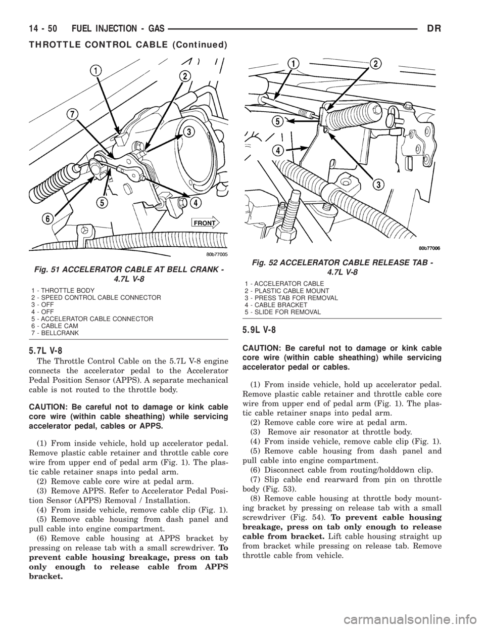
(7) Slip cable end rearward from pin on throttle
body (Fig. 53).
(8) Remove cable housing at throttle body mount-
ing bracket by pressing on release tab with a small
screwdriver (Fig. 54).To prevent cable housing
breakage, press on tab only enough to release
cable from bracket.Lift cable housing straight up
from bracket while pressing on release tab. Remove
throttle cable from vehicle.
Fig. 51 ACCELERATOR CABLE AT BELL CRANK -
4.7L V-8
1 - THROTTLE BODY
2 - SPEED CONTROL CABLE CONNECTOR
3 - OFF
4 - OFF
5 - ACCELERATOR CABLE CONNECTOR
6 - CABLE CAM
7 - BELLCRANK
Fig. 52 ACCELERATOR CABLE RELEASE TAB -
4.7L V-8
1 - ACCELERATOR CABLE
2 - PLASTIC CABLE MOUNT
3 - PRESS TAB FOR REMOVAL
4 - CABLE BRACKET
5 - SLIDE FOR REMOVAL
14 - 50 FUEL INJECTION - GASDR
THROTTLE CONTROL CABLE (Continued)
Page 1748 of 2895
8.0L V-10
CAUTION: Be careful not to damage or kink cable
core wire (within cable sheathing) while servicing
accelerator pedal or cables.
(1) From inside vehicle, hold up accelerator pedal.
Remove plastic cable retainer and throttle cable core
wire from upper end of pedal arm (Fig. 1). The plas-
tic cable retainer snaps into pedal arm.
(2) Remove cable core wire at pedal arm.(3) Remove necessary air intake tubes and resona-
tor housing.
(4) From inside vehicle, pinch both sides of plastic
cable housing retainer tabs at dash panel (Fig. 1).
(5) Remove cable housing from dash panel and
pull cable into engine compartment.
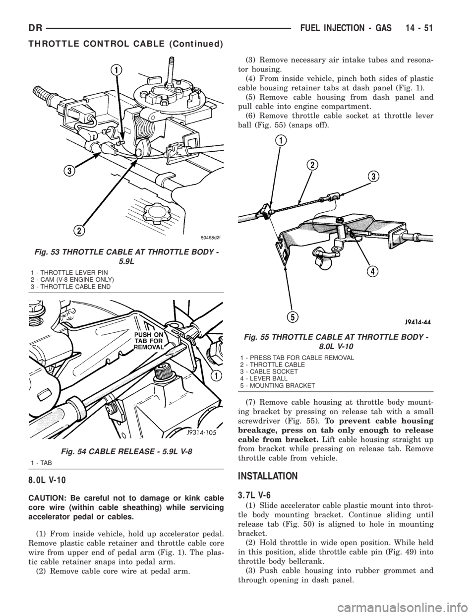
(6) Remove throttle cable socket at throttle lever
ball (Fig. 55) (snaps off).
(7) Remove cable housing at throttle body mount-
ing bracket by pressing on release tab with a small
screwdriver (Fig. 55).To prevent cable housing
breakage, press on tab only enough to release
cable from bracket.Lift cable housing straight up
from bracket while pressing on release tab. Remove
throttle cable from vehicle.
INSTALLATION
3.7L V-6
(1) Slide accelerator cable plastic mount into throt-
tle body mounting bracket. Continue sliding until
release tab (Fig. 50) is aligned to hole in mounting
bracket.
(2) Hold throttle in wide open position. While held
in this position, slide throttle cable pin (Fig. 49) into
throttle body bellcrank.
(3) Push cable housing into rubber grommet and
through opening in dash panel.
Fig. 53 THROTTLE CABLE AT THROTTLE BODY -
5.9L
1 - THROTTLE LEVER PIN
2 - CAM (V-8 ENGINE ONLY)
3 - THROTTLE CABLE END
Fig. 54 CABLE RELEASE - 5.9L V-8
1-TAB
Fig. 55 THROTTLE CABLE AT THROTTLE BODY -
8.0L V-10
1 - PRESS TAB FOR CABLE REMOVAL
2 - THROTTLE CABLE
3 - CABLE SOCKET
4 - LEVER BALL
5 - MOUNTING BRACKET
DRFUEL INJECTION - GAS 14 - 51
THROTTLE CONTROL CABLE (Continued)
Page 1749 of 2895
(4) From inside vehicle, install metal clip holding
cable to dashpanel (Fig. 1).
(5) From inside vehicle, slide throttle cable core
wire into opening (slot) in top of pedal arm.
(6) Push plastic cable retainer (clip) into pedal arm
opening until it snaps in place.
(7) Install air resonator tube to throttle body.
(8) Before starting engine, operate accelerator
pedal to check for any binding.
4.7L V-8
(1) Slide accelerator cable plastic mount into
bracket. Continue sliding until tab (Fig. 52) is
aligned to hole in mounting bracket.
(2) Route accelerator cable over top of cable cam.
(3) Connect cable end to throttle body bellcrank
pin (snaps on rearward).
(4) Slide rubber grommet away from plastic cable
housing.
(5) Install rubber grommet into dash panel until
seated.
(6) Push cable housing into rubber grommet and
through opening in dash panel.
(7) From inside vehicle, install clip holding cable
to dashpanel (Fig. 1).
(8) From inside vehicle, slide throttle cable core
wire into opening in top of pedal arm.
(9) Push cable retainer (clip) into pedal arm open-
ing until it snaps in place.
(10) Snap cable into dashpanel routing clip.
(11) Install air resonator tube to throttle body.
(12) Before starting engine, operate accelerator
pedal to check for any binding.
5.7L V-8
(1) Attach cable to Accelerator Pedal Position Sen-
sor (APPS). Refer to APPS Removal / Installation.
(2) Push cable housing into rubber grommet and
through opening in dash panel.
(3) From inside vehicle, install clip holding cable
to dashpanel (Fig. 1).
(4) From inside vehicle, slide throttle cable core
wire into opening in top of pedal arm.
(5) Push cable retainer (clip) into pedal arm open-
ing until it snaps in place.
(6) Before starting engine, operate accelerator
pedal to check for any binding.
(7) If necessary, use DRB IIItScan Tool to erase
any APPS Diagnostic Trouble Codes (DTC's) from
PCM.
5.9L V-8
(1) Slide accelerator cable plastic mount into throt-
tle body mounting bracket. Continue sliding until
release tab (Fig. 54) is aligned to hole in mounting
bracket.(2) Hold throttle in wide open position. While held
in this position, slide throttle cable pin into throttle
body bellcrank.
(3) Push cable housing into rubber grommet and
through opening in dash panel.
(4) From inside vehicle, install metal clip holding
cable to dashpanel (Fig. 1).
(5) From inside vehicle, slide throttle cable core
wire into opening (slot) in top of pedal arm.
(6) Push plastic cable retainer (clip) into pedal arm
opening until it snaps in place.
(7) Install air resonator tube to throttle body.
(8) Before starting engine, operate accelerator
pedal to check for any binding.
8.0L V-10
(1) Connect cable end socket to throttle body lever
ball (snaps on) (Fig. 55).
(2) Connect cable to throttle body mounting
bracket (push down and lock)
(3) Install the remaining cable housing end into
and through the dash panel opening (snaps into posi-
tion). The two plastic pinch tabs (Fig. 1) should lock
the cable to dash panel.
(4) From inside the vehicle, hold up the accelera-
tor pedal. Install the throttle cable core wire and
plastic cable retainer into and through the upper end
of the pedal arm (the plastic retainer is snapped into
the pedal arm). When installing the plastic retainer
to the accelerator pedal arm, note the index tab on
the pedal arm (Fig. 1). Align the index slot on the
plastic cable retainer to this index tab.
(5) Install air resonator tube to throttle body.
(6) Before starting engine, operate accelerator
pedal to check for any binding.
THROTTLE POSITION SENSOR
DESCRIPTION
The 3-wire Throttle Position Sensor (TPS) is
mounted on the throttle body and is connected to the
throttle blade shaft.
The 5.7L V-8 engine does not use a separate TPS
on the throttle body.
OPERATION
The 5.7L V-8 engine does not use a separate Throt-
tle Position Sensor (TPS) on the throttle body.
The 3±wire TPS provides the Powertrain Control
Module (PCM) with an input signal (voltage) that
represents the throttle blade position of the throttle
body. The sensor is connected to the throttle blade
shaft. As the position of the throttle blade changes,
the output voltage of the TPS changes.
14 - 52 FUEL INJECTION - GASDR
THROTTLE CONTROL CABLE (Continued)
Page 1791 of 2895
INSTALLATION
(1) Check condition of sensor o-ring.
(2) Clean sensor mounting area at intake manifold
(3) Position sensor into intake manifold.
(4) Install and tighten 2 screws.
(5) Connect electrical connector to sensor.
MAP SENSOR
DESCRIPTION
A combination, dual function Intake Manifold Air
Temperature Sensor/MAP Sensor is used. Refer to
Intake Air Temperature Sensor/MAP Sensor for infor-
mation.
THROTTLE CONTROL CABLE
REMOVAL
Early Diesel Engine
(1) Disconnect both negative battery cables at both
batteries.
(2) From inside vehicle, hold up accelerator pedal.
Remove plastic cable retainer and throttle cable core
wire from upper end of pedal arm (Fig. 33). The plas-
tic cable retainer snaps into pedal arm.
(3) From inside vehicle, remove cable clip (Fig. 33).
(4) Remove cable core wire at pedal arm.
(5) Remove cable housing from dash panel and
pull cable into engine compartment.
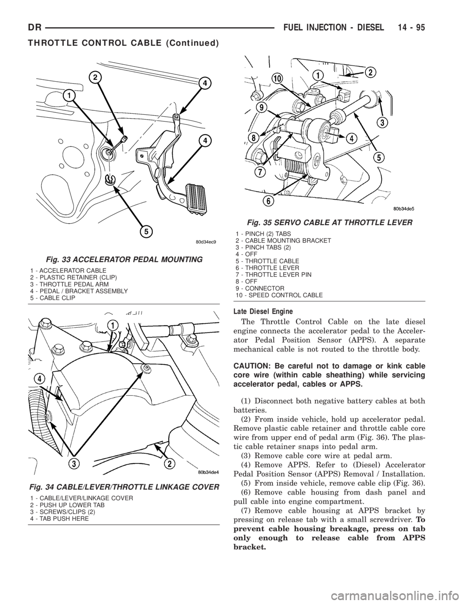
(6) Remove cable cover (Fig. 34). Cable cover is
attached with 2 Phillips screws, 2 plastic retention
clips and 2 push tabs (Fig. 34). Remove 2 Phillips
screws and carefully pry out 2 retention clips. After
clip removal, push rearward on front tab, and
upward on lower tab for cover removal.
(7) Using 2 screwdrivers, pry cable connector
socket from throttle lever ball (Fig. 35).Be very
careful not to bend throttle lever arm.
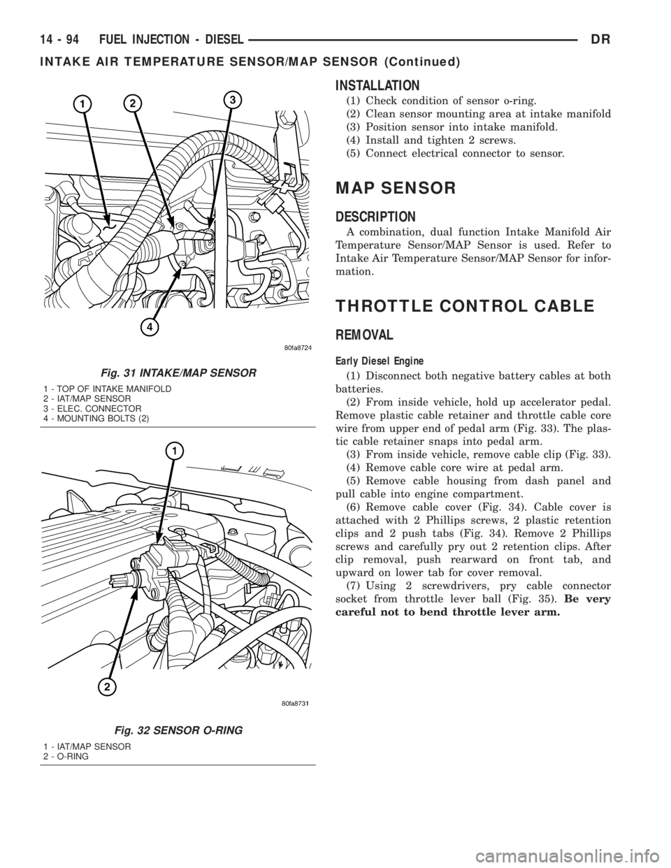
Fig. 31 INTAKE/MAP SENSOR
1 - TOP OF INTAKE MANIFOLD
2 - IAT/MAP SENSOR
3 - ELEC. CONNECTOR
4 - MOUNTING BOLTS (2)
Fig. 32 SENSOR O-RING
1 - IAT/MAP SENSOR
2 - O-RING
14 - 94 FUEL INJECTION - DIESELDR
INTAKE AIR TEMPERATURE SENSOR/MAP SENSOR (Continued)
Page 1792 of 2895
Late Diesel Engine
The Throttle Control Cable on the late diesel
engine connects the accelerator pedal to the Acceler-
ator Pedal Position Sensor (APPS). A separate
mechanical cable is not routed to the throttle body.
CAUTION: Be careful not to damage or kink cable
core wire (within cable sheathing) while servicing
accelerator pedal, cables or APPS.
(1) Disconnect both negative battery cables at both
batteries.
(2) From inside vehicle, hold up accelerator pedal.
Remove plastic cable retainer and throttle cable core
wire from upper end of pedal arm (Fig. 36). The plas-
tic cable retainer snaps into pedal arm.
(3) Remove cable core wire at pedal arm.
(4) Remove APPS. Refer to (Diesel) Accelerator
Pedal Position Sensor (APPS) Removal / Installation.
(5) From inside vehicle, remove cable clip (Fig. 36).
(6) Remove cable housing from dash panel and
pull cable into engine compartment.
(7) Remove cable housing at APPS bracket by
pressing on release tab with a small screwdriver.To
prevent cable housing breakage, press on tab
only enough to release cable from APPS
bracket.
Fig. 33 ACCELERATOR PEDAL MOUNTING
1 - ACCELERATOR CABLE
2 - PLASTIC RETAINER (CLIP)
3 - THROTTLE PEDAL ARM
4 - PEDAL / BRACKET ASSEMBLY
5 - CABLE CLIP
Fig. 34 CABLE/LEVER/THROTTLE LINKAGE COVER
1 - CABLE/LEVER/LINKAGE COVER
2 - PUSH UP LOWER TAB
3 - SCREWS/CLIPS (2)
4 - TAB PUSH HERE
Fig. 35 SERVO CABLE AT THROTTLE LEVER
1 - PINCH (2) TABS
2 - CABLE MOUNTING BRACKET
3 - PINCH TABS (2)
4 - OFF
5 - THROTTLE CABLE
6 - THROTTLE LEVER
7 - THROTTLE LEVER PIN
8 - OFF
9 - CONNECTOR
10 - SPEED CONTROL CABLE
DRFUEL INJECTION - DIESEL 14 - 95
THROTTLE CONTROL CABLE (Continued)
Page 1793 of 2895
INSTALLATION
Early Diesel Engine
(1) Install cable through mounting hole on cable
mounting bracket (Fig. 35). Cable snaps into bracket.
Be sure 2 pinch tabs are secure.
(2) Using large pliers, connect cable end socket to
throttle lever ball (snaps on).(3) Install remaining cable housing end into and
through dash panel opening (snaps into position).
The two plastic pinch tabs should lock cable to dash
panel.
(4) From inside vehicle, hold up accelerator pedal.
Install throttle cable core wire and plastic cable
retainer into and through upper end of pedal arm
(the plastic retainer is snapped into pedal arm).
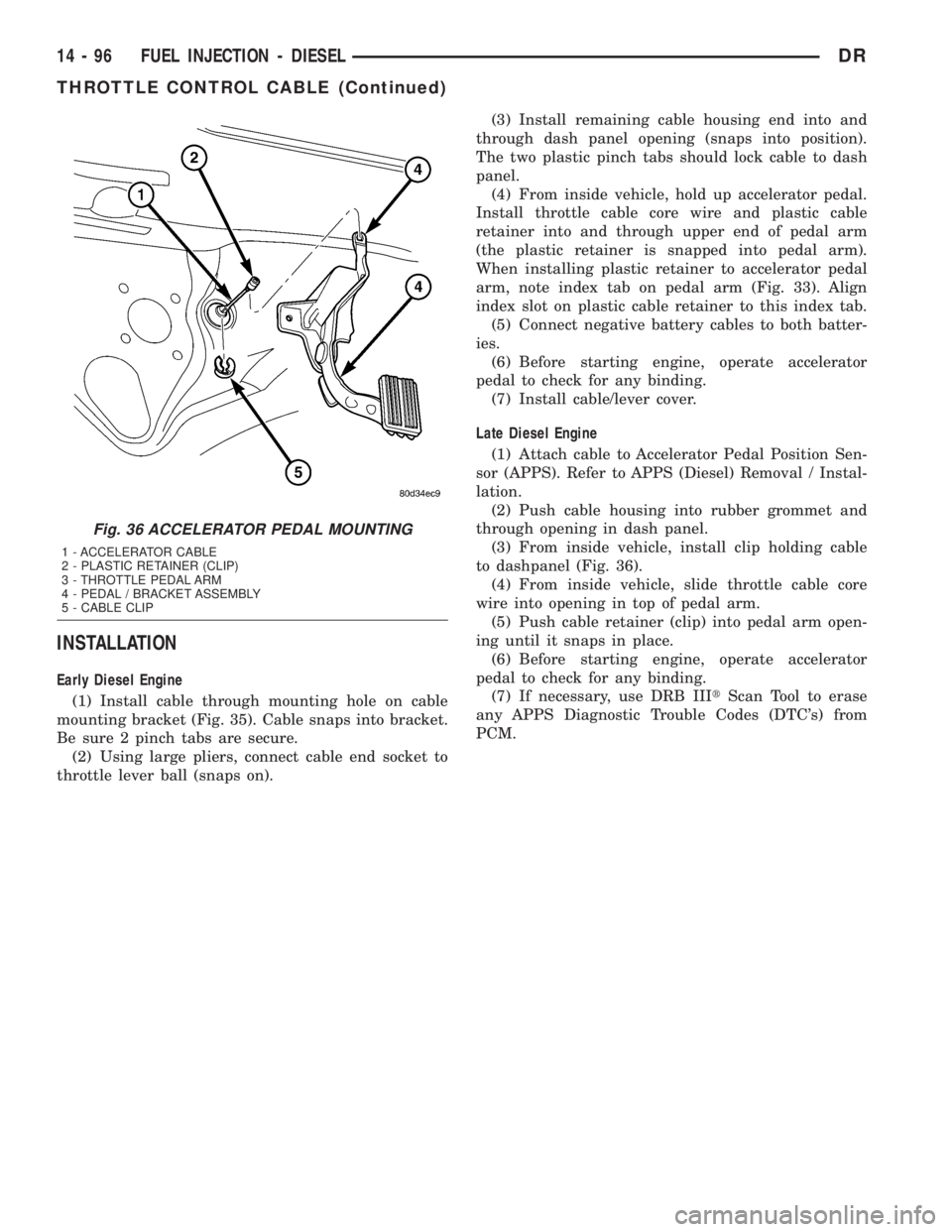
When installing plastic retainer to accelerator pedal
arm, note index tab on pedal arm (Fig. 33). Align
index slot on plastic cable retainer to this index tab.
(5) Connect negative battery cables to both batter-
ies.
(6) Before starting engine, operate accelerator
pedal to check for any binding.
(7) Install cable/lever cover.
Late Diesel Engine
(1) Attach cable to Accelerator Pedal Position Sen-
sor (APPS). Refer to APPS (Diesel) Removal / Instal-
lation.
(2) Push cable housing into rubber grommet and
through opening in dash panel.
(3) From inside vehicle, install clip holding cable
to dashpanel (Fig. 36).
(4) From inside vehicle, slide throttle cable core
wire into opening in top of pedal arm.
(5) Push cable retainer (clip) into pedal arm open-
ing until it snaps in place.
(6) Before starting engine, operate accelerator
pedal to check for any binding.
(7) If necessary, use DRB IIItScan Tool to erase
any APPS Diagnostic Trouble Codes (DTC's) from
PCM.
Fig. 36 ACCELERATOR PEDAL MOUNTING
1 - ACCELERATOR CABLE
2 - PLASTIC RETAINER (CLIP)
3 - THROTTLE PEDAL ARM
4 - PEDAL / BRACKET ASSEMBLY
5 - CABLE CLIP
14 - 96 FUEL INJECTION - DIESELDR
THROTTLE CONTROL CABLE (Continued)