2003 DODGE RAM Abs control module
[x] Cancel search: Abs control modulePage 1183 of 2895
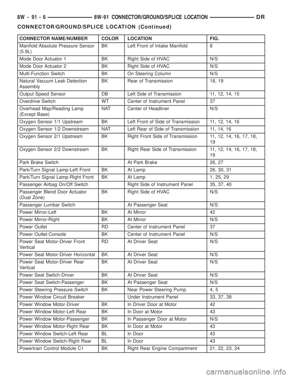
CONNECTOR NAME/NUMBER COLOR LOCATION FIG.
Manifold Absolute Pressure Sensor
(5.9L)BK Left Front of Intake Manifold 8
Mode Door Actuator 1 BK Right Side of HVAC N/S
Mode Door Actuator 2 BK Right Side of HVAC N/S
Multi-Function Switch BK On Steering Column N/S
Natural Vacuum Leak Detection
AssemblyBK Rear of Transmission 18, 19
Output Speed Sensor DB Left Side of Transmission 11, 12, 14, 15
Overdrive Switch WT Center of Instrument Panel 37
Overhead Map/Reading Lamp
(Except Base)NAT Center of Headliner N/S
Oxygen Sensor 1/1 Upstream BK Left Front of Side of Transmission 11, 12, 14, 16
Oxygen Sensor 1/2 Downstream NAT Left Rear of Side of Transmission 11, 14, 16
Oxygen Sensor 2/1 Upstream BK Right Front Side of Transmission 11, 12, 14, 16, 17, 18,
19
Oxygen Sensor 2/2 Downstream BK Right Rear Side of Transmission 11, 12, 14, 16, 17, 18,
19
Park Brake Switch At Park Brake 26, 27
Park/Turn Signal Lamp-Left Front BK At Lamp 26, 30, 31
Park/Turn Signal Lamp-Right Front BK At Lamp 1, 25, 29
Passenger Airbag On/Off Switch Right Side of Instrument Panel 35, 37, 40
Passenger Blend Door Actuator
(Dual Zone)BK Right Side of HVAC N/S
Passenger Lumbar Switch At Passenger Seat N/S
Power Mirror-Left BK At Mirror 42
Power Mirror-Right BK At Mirror N/S
Power Outlet RD Center of Instrument Panel 37
Power Outlet-Console BK Center of Instrument Panel N/S
Power Seat Motor-Driver Front
VerticalRD At Driver Seat N/S
Power Seat Motor-Driver Horizontal BK At Driver Seat N/S
Power Seat Motor-Driver Rear
VerticalBK At Driver Seat N/S
Power Seat Switch-Driver BK At Driver Seat N/S
Power Seat Switch-Passenger BK At Passenger Seat N/S
Power Steering Pressure Switch BK Near Power Steering Pump 4, 5
Power Window Circuit Breaker Under Instrument Panel 33, 37, 39
Power Window Motor-Driver BK In Driver Door at Motor 42
Power Window Motor-Left Rear BK In Door at Motor 43
Power Window Motor-Passenger BK In Passenger Door at Motor N/S
Power Window Motor-Right Rear BK In Door at Motor 43
Power Window Switch-Left Rear BL In Door 43
Power Window Switch-Right Rear BL In Door 43
Powertrain Control Module C1 BK Right Rear Engine Compartment 21, 22, 23, 24
8W - 91 - 6 8W-91 CONNECTOR/GROUND/SPLICE LOCATIONDR
CONNECTOR/GROUND/SPLICE LOCATION (Continued)
Page 1244 of 2895
tery and provides the primary means of circuit pro-
tection and power distribution for all vehicle
electrical systems. The front control module controls
power to some of these vehicle systems electrical and
electromechanical loads based on inputs received
from hard wired switch inputs and data received on
the PCI bus circuit (J1850).
For information on theIntegrated Power Mod-
ule Refer to the Power Distribution Sectionof
the service manual.
OPERATION
As messages are sent over the PCI bus circuit, the
front control module reads these messages and con-
trols power to some of the vehicles electrical systems
by completing the circuit to ground (low side driver)
or completing the circuit to 12 volt power (high side
driver). The following functions areControlledby
the Front Control Module:
²Headlamp Power with Voltage Regulation
²Windshield Wiper ªON/OFFº Relay Actuation
²Windshield Wiper ªHI/LOº Relay Actuation
²Windshield Washer Pump Motor
²Fog Lamp Relay Actuation
²Park Lamp Relay Actuation
²Horn Relay Actuation
The following inputs areReceived/Monitoredby
the Front Control Module:
²B+ Connection Detection²Power Ground
²Ambient Temperature Sensing
²Ignition Switch Run
²Washer Fluid Level Switch
²Windshield Wiper Park Switch
²PCI Bus Circuit
DIAGNOSIS AND TESTING - FRONT CONTROL
MODULE
The front control module is a printed circuit board
based module with a on-board micro-processor. The
front control module interfaces with other electronic
modules in the vehicle via the Programmable Com-
munications Interface (PCI) data bus (J1850). In
order to obtain conclusive testing the Programmable
Communications Interface (PCI) data bus network
and all of the electronic modules that provide inputs
to, or receive outputs from the front control module
must be checked. All PCI (J1850) communication
faults must be resolved prior to further diagnosing
any front control module related issues.
The front control module was designed to be diag-
nosed with an appropriate diagnostic scan tool, such
as the DRB IIIt. The most reliable, efficient, and
accurate means to diagnose the front control module
requires the use of a DRB IIItscan tool and the
proper Body Diagnostic Procedures manual.
Before any testing of the front control module is
attempted, the battery should be fully charged and
all wire harness and ground connections inspected
around the affected areas on the vehicle.
REMOVAL
(1) Disconnect the positive and negative battery
cables from the battery.
(2) Partially remove the integrated power module
from the engine compartment (Refer to 8 - ELECTRI-
CAL/POWER DISTRIBUTION/INTEGRATED
POWER MODULE - REMOVAL).
(3)
Remove the front control module retaining
screws.
(4) Using both hands, pull the front control module
straightfrom the integrated power module assembly
to disconnect the 49-way electrical connector and
remove the front control module from the vehicle.
INSTALLATION
(1) Install the front control module on the inte-
grated power module assembly by pushing the
49-way electrical connector straight in.
(2) Install the front control module retaining
screws. Torque the screws to 7 in. lbs.
(3) Install the integrated power module (Refer to 8
- ELECTRICAL/POWER DISTRIBUTION/INTE-
GRATED POWER MODULE - INSTALLATION).
(4)
Connect the positive and negative battery cables.
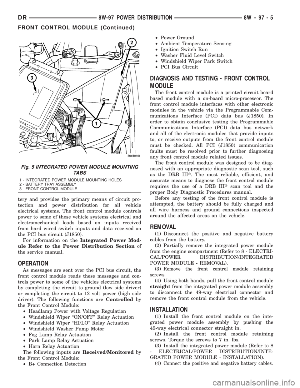
Fig. 5 INTEGRATED POWER MODULE MOUNTING
TABS
1 - INTEGRATED POWER MODULE MOUNTING HOLES
2 - BATTERY TRAY ASSEMBLY
3 - FRONT CONTROL MODULE
DR8W-97 POWER DISTRIBUTION 8W - 97 - 5
FRONT CONTROL MODULE (Continued)
Page 1260 of 2895
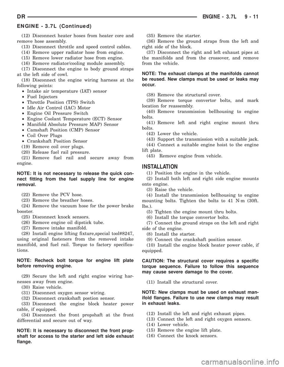
(12) Disconnect heater hoses from heater core and
remove hose assembly.
(13) Disconnect throttle and speed control cables.
(14) Remove upper radiator hose from engine.
(15) Remove lower radiator hose from engine.
(16) Remove radiator/cooling module assembly.
(17) Disconnect the engine to body ground straps
at the left side of cowl.
(18) Disconnect the engine wiring harness at the
following points:
²Intake air temperature (IAT) sensor
²Fuel Injectors
²Throttle Position (TPS) Switch
²Idle Air Control (IAC) Motor
²Engine Oil Pressure Switch
²Engine Coolant Temperature (ECT) Sensor
²Manifold Absolute Pressure MAP) Sensor
²Camshaft Position (CMP) Sensor
²Coil Over Plugs
²Crankshaft Position Sensor
(19) Remove coil over plugs.
(20) Release fuel rail pressure.
(21) Remove fuel rail and secure away from
engine.
NOTE: It is not necessary to release the quick con-
nect fitting from the fuel supply line for engine
removal.
(22) Remove the PCV hose.
(23) Remove the breather hoses.
(24) Remove the vacuum hose for the power brake
booster.
(25) Disconnect knock sensors.
(26) Remove engine oil dipstick tube.
(27) Remove intake manifold.
(28) Install engine lifting fixture,special tool#8247,
using original fasteners from the removed intake
manifold, and fuel rail. Torque to factory specifica-
tions.
NOTE: Recheck bolt torque for engine lift plate
before removing engine.
(29) Secure the left and right engine wiring har-
nesses away from engine.
(30) Raise vehicle.
(31) Disconnect oxygen sensor wiring.
(32) Disconnect crankshaft postion sensor.
(33) Disconnect the engine block heater power
cable, if equipped.
(34) Disconnect the front propshaft at the front
differential and secure out of way.
NOTE: It is necessary to disconnect the front prop-
shaft for access to the starter and left side exhaust
flange.(35) Remove the starter.
(36) Remove the ground straps from the left and
right side of the block.
(37) Disconnect the right and left exhaust pipes at
the manifolds and from the crossover, and remove
from the vehicle.
NOTE: The exhaust clamps at the manifolds cannot
be reused. New clamps must be used or leaks may
occur.
(38) Remove the structural cover.
(39) Remove torque convertor bolts, and mark
location for reassembly.
(40) Remove transmission bellhousing to engine
bolts.
(41) Remove left and right engine mount thru
bolts.
(42) Lower the vehicle.
(43) Support the transmission with a suitable jack.
(44) Connect a suitable engine hoist to the engine
lift plate.
(45) Remove engine from vehicle.
INSTALLATION
(1) Position the engine in the vehicle.
(2) Install both left and right side engine mounts
onto engine.
(3) Raise the vehicle.
(4) Install the transmission bellhousing to engine
mounting bolts. Tighten the bolts to 41 N´m (30ft.
lbs.).
(5) Tighten the engine mount thru bolts.
(6) Install the torque convertor bolts.
(7) Connect the ground straps on the left and right
side of the engine.
(8) Install the starter.
(9) Connect the crankshaft position sensor.
(10) Install the engine block heater power cable, if
equipped.
CAUTION: The structural cover requires a specific
torque sequence. Failure to follow this sequence
may cause severe damage to the cover.
(11) Install the structural cover.
NOTE: New clamps must be used on exhaust man-
ifold flanges. Failure to use new clamps may result
in exhaust leaks.
(12) Install the left and right exhaust pipes.
(13) Connect the left and right oxygen sensors.
(14) Lower vehicle.
(15) Remove the engine lift plate.
(16) Connect the knock sensors.
DRENGINE - 3.7L 9 - 11
ENGINE - 3.7L (Continued)
Page 1261 of 2895
(17) Connect the engine to body ground straps at
the left side of the cowl.
(18) Install the intake manifold.
(19) Install the engine oil dipstick tube.
(20) Install the power brake booster vacuum hose.
(21) Install the breather hoses.
(22) Install the PCV hose.
(23) Install the fuel rail.
(24) Install the coil over plugs.
(25) Connect the engine wiring harness at the fol-
lowing points:
²Intake air temperature (IAT) sensor
²Fuel Injectors
²Throttle Position (TPS) Switch
²Idle Air Control (IAC) Motor
²Engine Oil Pressure Switch
²Engine Coolant Temperature (ECT) Sensor
²Manifold Absolute Pressure MAP) Sensor
²Camshaft Position (CMP) Sensor
²Coil Over Plugs
²Crankshaft Position Sensor
(26) Reinstall the radiator/cooling module assem-
bly.
(27) Connect lower radiator hose.
(28) Connect upper radiator hose.
(29) Connect throttle and speed control cables.
(30) Install the heater hose assembly.
(31) Install coolant recovery bottle.
(32) Install the power steering pump.
(33) Install the generator.
(34) Install the A/C compressor.
(35) Install the drive belt.
(36) Install the fan shroud with the viscous fan
assembly.
(37) Install the radiator core support bracket.
(38) Install the air cleaner assembly.
(39) Refill the engine cooling system.
(40) Recharge the air conditioning.
(41) Install the hood.
(42) Check and fill engine oil.
(43) Connect the battery negative cable.
(44) Start the engine and check for leaks.SPECIFICATIONS
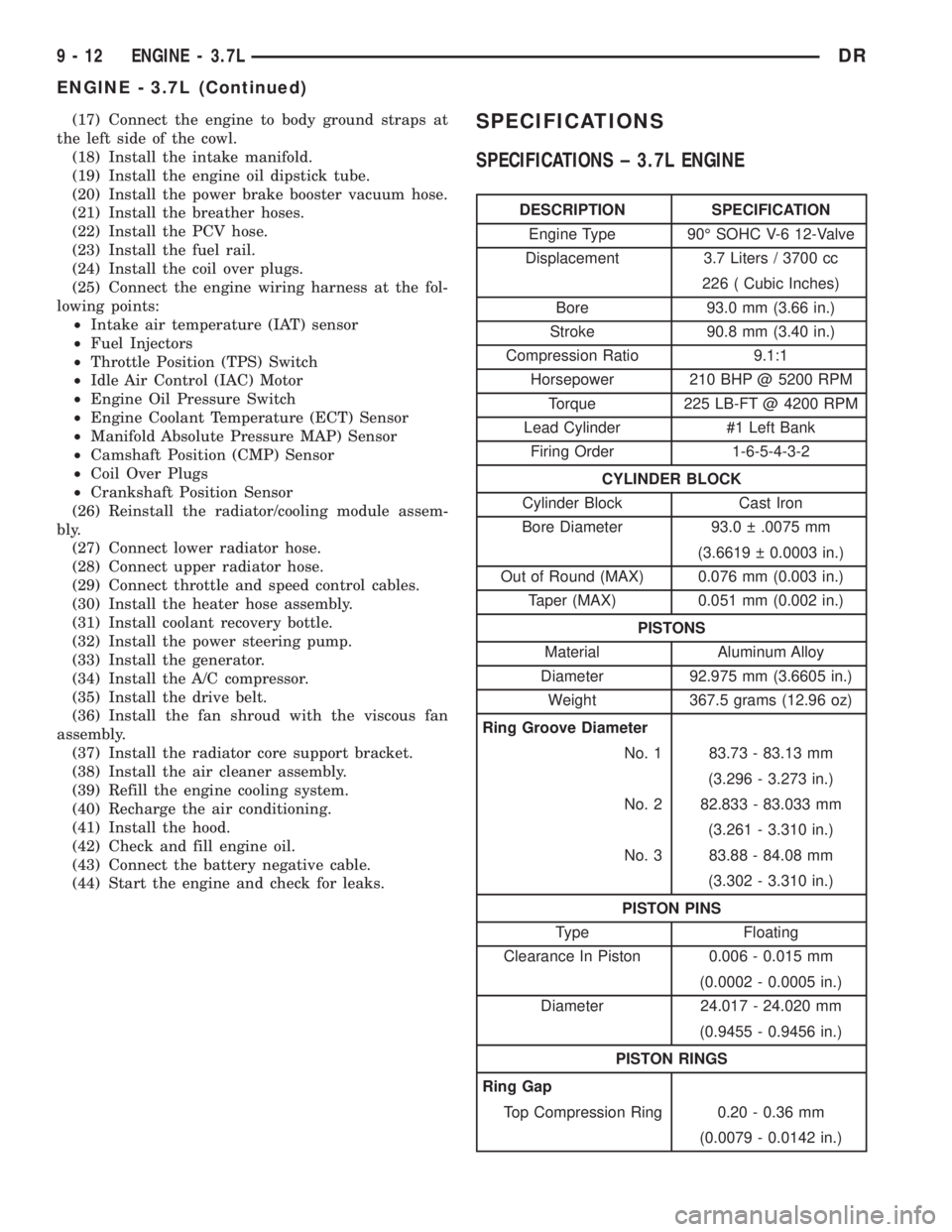
SPECIFICATIONS ± 3.7L ENGINE
DESCRIPTION SPECIFICATION
Engine Type 90É SOHC V-6 12-Valve
Displacement 3.7 Liters / 3700 cc
226 ( Cubic Inches)
Bore 93.0 mm (3.66 in.)
Stroke 90.8 mm (3.40 in.)
Compression Ratio 9.1:1
Horsepower 210 BHP @ 5200 RPM
Torque 225 LB-FT @ 4200 RPM
Lead Cylinder #1 Left Bank
Firing Order 1-6-5-4-3-2
CYLINDER BLOCK
Cylinder Block Cast Iron
Bore Diameter 93.0 .0075 mm
(3.6619 0.0003 in.)
Out of Round (MAX) 0.076 mm (0.003 in.)
Taper (MAX) 0.051 mm (0.002 in.)
PISTONS
Material Aluminum Alloy
Diameter 92.975 mm (3.6605 in.)
Weight 367.5 grams (12.96 oz)
Ring Groove Diameter
No. 1 83.73 - 83.13 mm
(3.296 - 3.273 in.)
No. 2 82.833 - 83.033 mm
(3.261 - 3.310 in.)
No. 3 83.88 - 84.08 mm
(3.302 - 3.310 in.)
PISTON PINS
Type Floating
Clearance In Piston 0.006 - 0.015 mm
(0.0002 - 0.0005 in.)
Diameter 24.017 - 24.020 mm
(0.9455 - 0.9456 in.)
PISTON RINGS
Ring Gap
Top Compression Ring 0.20 - 0.36 mm
(0.0079 - 0.0142 in.)
9 - 12 ENGINE - 3.7LDR
ENGINE - 3.7L (Continued)
Page 1736 of 2895
(1) Install sensor to intake manifold. Tighten to
12±15 N´m (110±130 in. lbs.) torque.
(2) Install electrical connector.
MAP SENSOR
DESCRIPTION
3.7L V-6
The Manifold Absolute Pressure (MAP) sensor is
mounted into the front of the intake manifold with 2
screws.
4.7L V-8
The Manifold Absolute Pressure (MAP) sensor is
mounted into the front of the intake manifold with 2
screws.
5.7L V-8
The Manifold Absolute Pressure (MAP) sensor is
mounted to the front of the intake manifold air ple-
num box.
5.9L V-8
The Manifold Absolute Pressure (MAP) sensor is
mounted to the front of the throttle body with 2
screws.
8.0L V-10
The Manifold Absolute Pressure (MAP) sensor is
mounted into the right side of the intake manifold.
OPERATION
The MAP sensor is used as an input to the Power-
train Control Module (PCM). It contains a silicon
based sensing unit to provide data on the manifold
vacuum that draws the air/fuel mixture into the com-
bustion chamber. The PCM requires this information
to determine injector pulse width and spark advance.
When manifold absolute pressure (MAP) equals
Barometric pressure, the pulse width will be at max-
imum.
A 5 volt reference is supplied from the PCM and
returns a voltage signal to the PCM that reflects
manifold pressure. The zero pressure reading is 0.5V
and full scale is 4.5V. For a pressure swing of 0±15
psi, the voltage changes 4.0V. To operate the sensor,
it is supplied a regulated 4.8 to 5.1 volts. Ground is
provided through the low-noise, sensor return circuit
at the PCM.
The MAP sensor input is the number one contrib-
utor to fuel injector pulse width. The most important
function of the MAP sensor is to determine baromet-
ric pressure. The PCM needs to know if the vehicle is
at sea level or at a higher altitude, because the airdensity changes with altitude. It will also help to cor-
rect for varying barometric pressure. Barometric
pressure and altitude have a direct inverse correla-
tion; as altitude goes up, barometric goes down. At
key-on, the PCM powers up and looks at MAP volt-
age, and based upon the voltage it sees, it knows the
current barometric pressure (relative to altitude).
Once the engine starts, the PCM looks at the voltage
again, continuously every 12 milliseconds, and com-
pares the current voltage to what it was at key-on.
The difference between current voltage and what it
was at key-on, is manifold vacuum.
During key-on (engine not running) the sensor
reads (updates) barometric pressure. A normal range
can be obtained by monitoring a known good sensor.
As the altitude increases, the air becomes thinner
(less oxygen). If a vehicle is started and driven to a
very different altitude than where it was at key-on,
the barometric pressure needs to be updated. Any
time the PCM sees Wide Open Throttle (WOT), based
upon Throttle Position Sensor (TPS) angle and RPM,
it will update barometric pressure in the MAP mem-
ory cell. With periodic updates, the PCM can make
its calculations more effectively.
The PCM uses the MAP sensor input to aid in cal-
culating the following:
²Manifold pressure
²Barometric pressure
²Engine load
²Injector pulse-width
²Spark-advance programs
²Shift-point strategies (certain automatic trans-
missions only)
²Idle speed
²Decel fuel shutoff
The MAP sensor signal is provided from a single
piezoresistive element located in the center of a dia-
phragm. The element and diaphragm are both made
of silicone. As manifold pressure changes, the dia-
phragm moves causing the element to deflect, which
stresses the silicone. When silicone is exposed to
stress, its resistance changes. As manifold vacuum
increases, the MAP sensor input voltage decreases
proportionally. The sensor also contains electronics
that condition the signal and provide temperature
compensation.
The PCM recognizes a decrease in manifold pres-
sure by monitoring a decrease in voltage from the
reading stored in the barometric pressure memory
cell. The MAP sensor is a linear sensor; meaning as
pressure changes, voltage changes proportionately.
The range of voltage output from the sensor is usu-
ally between 4.6 volts at sea level to as low as 0.3
volts at 26 in. of Hg. Barometric pressure is the pres-
sure exerted by the atmosphere upon an object. At
sea level on a standard day, no storm, barometric
DRFUEL INJECTION - GAS 14 - 39
INTAKE AIR TEMPERATURE SENSOR (Continued)
Page 1749 of 2895
(4) From inside vehicle, install metal clip holding
cable to dashpanel (Fig. 1).
(5) From inside vehicle, slide throttle cable core
wire into opening (slot) in top of pedal arm.
(6) Push plastic cable retainer (clip) into pedal arm
opening until it snaps in place.
(7) Install air resonator tube to throttle body.
(8) Before starting engine, operate accelerator
pedal to check for any binding.
4.7L V-8
(1) Slide accelerator cable plastic mount into
bracket. Continue sliding until tab (Fig. 52) is
aligned to hole in mounting bracket.
(2) Route accelerator cable over top of cable cam.
(3) Connect cable end to throttle body bellcrank
pin (snaps on rearward).
(4) Slide rubber grommet away from plastic cable
housing.
(5) Install rubber grommet into dash panel until
seated.
(6) Push cable housing into rubber grommet and
through opening in dash panel.
(7) From inside vehicle, install clip holding cable
to dashpanel (Fig. 1).
(8) From inside vehicle, slide throttle cable core
wire into opening in top of pedal arm.
(9) Push cable retainer (clip) into pedal arm open-
ing until it snaps in place.
(10) Snap cable into dashpanel routing clip.
(11) Install air resonator tube to throttle body.
(12) Before starting engine, operate accelerator
pedal to check for any binding.
5.7L V-8
(1) Attach cable to Accelerator Pedal Position Sen-
sor (APPS). Refer to APPS Removal / Installation.
(2) Push cable housing into rubber grommet and
through opening in dash panel.
(3) From inside vehicle, install clip holding cable
to dashpanel (Fig. 1).
(4) From inside vehicle, slide throttle cable core
wire into opening in top of pedal arm.
(5) Push cable retainer (clip) into pedal arm open-
ing until it snaps in place.
(6) Before starting engine, operate accelerator
pedal to check for any binding.
(7) If necessary, use DRB IIItScan Tool to erase
any APPS Diagnostic Trouble Codes (DTC's) from
PCM.
5.9L V-8
(1) Slide accelerator cable plastic mount into throt-
tle body mounting bracket. Continue sliding until
release tab (Fig. 54) is aligned to hole in mounting
bracket.(2) Hold throttle in wide open position. While held
in this position, slide throttle cable pin into throttle
body bellcrank.
(3) Push cable housing into rubber grommet and
through opening in dash panel.
(4) From inside vehicle, install metal clip holding
cable to dashpanel (Fig. 1).
(5) From inside vehicle, slide throttle cable core
wire into opening (slot) in top of pedal arm.
(6) Push plastic cable retainer (clip) into pedal arm
opening until it snaps in place.
(7) Install air resonator tube to throttle body.
(8) Before starting engine, operate accelerator
pedal to check for any binding.
8.0L V-10
(1) Connect cable end socket to throttle body lever
ball (snaps on) (Fig. 55).
(2) Connect cable to throttle body mounting
bracket (push down and lock)
(3) Install the remaining cable housing end into
and through the dash panel opening (snaps into posi-
tion). The two plastic pinch tabs (Fig. 1) should lock
the cable to dash panel.
(4) From inside the vehicle, hold up the accelera-
tor pedal. Install the throttle cable core wire and
plastic cable retainer into and through the upper end
of the pedal arm (the plastic retainer is snapped into
the pedal arm). When installing the plastic retainer
to the accelerator pedal arm, note the index tab on
the pedal arm (Fig. 1). Align the index slot on the
plastic cable retainer to this index tab.
(5) Install air resonator tube to throttle body.
(6) Before starting engine, operate accelerator
pedal to check for any binding.
THROTTLE POSITION SENSOR
DESCRIPTION
The 3-wire Throttle Position Sensor (TPS) is
mounted on the throttle body and is connected to the
throttle blade shaft.
The 5.7L V-8 engine does not use a separate TPS
on the throttle body.
OPERATION
The 5.7L V-8 engine does not use a separate Throt-
tle Position Sensor (TPS) on the throttle body.
The 3±wire TPS provides the Powertrain Control
Module (PCM) with an input signal (voltage) that
represents the throttle blade position of the throttle
body. The sensor is connected to the throttle blade
shaft. As the position of the throttle blade changes,
the output voltage of the TPS changes.
14 - 52 FUEL INJECTION - GASDR
THROTTLE CONTROL CABLE (Continued)
Page 1765 of 2895
(4) Apply clean engine oilto injection pump
o-ring only.
The machined tapers on both injection pump
shaft and injection pump gear must be abso-
lutely dry, clean and free of any dirt or oil film.
This will ensure proper gear-to-shaft tighten-
ing.
(5) Clean pump gear and pump shaft at machined
tapers with an evaporative type cleaner such as
brake cleaner.
(6) Position injection pump to mounting flange on
gear cover while aligning injection pump shaft
through back of injection pump gear.
(7) After pump is positioned flat to mounting
flange, install 3 pump mounting nuts and tighten
finger tight only.Do not attempt a final tightening
at this time.Do not attempt to tighten (pull)
pump to gear cover using mounting nuts. Dam-
age to pump or gear cover may occur. The
pump must be positioned flat to its mounting
flange before attempting to tighten 3 mounting
nuts.
(8) To prevent damage or cracking of components,
install and tighten nuts in the following sequence:
(a) Install injection pump shaft washer and nut
to pump shaft. Tighten nutfinger tight only.
(b) Do preliminary (light) tightening of injection
pump shaft nut.
(c) Tighten 3 injection pump mounting nuts to 8
N´m (70.8 in. lbs.).
(d) Do a final tightening of pump shaft nut to
105 N´m (77 ft. lbs.).
(9) Install drive gear access cover (plate) using a
1/2 inch drive ratchet. Plate is threaded to timing
gear cover.
(10) Install Engine Control Module (ECM) to left
side of engine.
(11) Install fuel line (injection pump-to-overflow
valve). Tighten bolts to 24 N´m (17 ft. lbs.) torque.
(12) Install fuel line (injection pump-to-fuel rail).
Tighten to 24 N´m (17 ft. lbs.) torque.
(13) Install fuel line (injection pump-to-fuel filter
housing). Tighten to 24 N´m (17 ft. lbs.) torque.
(14) Connect Fuel Control Actuator (FCA) electri-
cal connector to rear of injection pump.
(15) Install intake manifold air intake tube (above
injection pump). Tighten clamps.
(16) Install accessory drive belt.
(17) Install cooling fan shroud.
(18) Install cooling fan assembly.
(19) Connect both negative battery cables to both
batteries.
(20) Check system for fuel or engine oil leaks.FUEL LEVEL SENDING UNIT /
SENSOR
DESCRIPTION
The fuel gauge sending unit (fuel level sensor) is
attached to the side of the fuel tank module. The
sending unit consists of a float, an arm, and a vari-
able resistor track (card).
OPERATION
The fuel tank module on diesel powered models
has 3 different circuits (wires). Two of these circuits
are used at the fuel gauge sending unit for fuel
gauge operation. The other wire is used for a ground.
The diesel engine does not have a fuel tank module
mounted electric fuel pump. The electric fuel pump
(fuel transfer pump) is mounted to the engine.
For Fuel Gauge Operation:A constant input
voltage source of about 12 volts (battery voltage) is
supplied to the resistor track on the fuel gauge send-
ing unit. This is fed directly from the Powertrain
Control Module (PCM).NOTE: For diagnostic pur-
poses, this 12V power source can only be veri-
fied with the circuit opened (fuel tank module
electrical connector unplugged). With the con-
nectors plugged, output voltages will vary from
about .6 volts at FULL, to about 7.0 volts at
EMPTY.The resistor track is used to vary the volt-
age (resistance) depending on fuel tank float level. As
fuel level increases, the float and arm move up,
which decreases voltage. As fuel level decreases, the
float and arm move down, which increases voltage.
The varied voltage signal is returned back to the
ECM through the sensor return circuit.
Both of the electrical circuits between the fuel
gauge sending unit and the ECM are hard-wired (not
multi-plexed). After the voltage signal is sent from
the resistor track, and back to the ECM, the ECM
will interpret the resistance (voltage) data and send
a message across the multi-plex bus circuits to the
instrument panel cluster. Here it is translated into
the appropriate fuel gauge level reading. Refer to
Instrument Panel for additional information.
REMOVAL
REMOVAL/INSTALLATION
For diesel removal and installation procedures,
refer to the gas section of Fuel System/Fuel Delivery.
See Fuel Level Sending Unit/Sensor Removal/Instal-
lation.
14 - 68 FUEL DELIVERY - DIESELDR
FUEL INJECTION PUMP (Continued)
Page 2036 of 2895
Normal calibration will be performed when sump
temperature is above 50 degrees F, or in the absence
of sump temperature data, after the first 10 minutes
of vehicle operation. Calibration of the pressure
transducer offset occurs each time the output shaft
speed falls below 200 RPM. Calibration shall be
repeated each 3 seconds the output shaft speed is
below 200 RPM. A 0.5 second pulse of 95% duty cycle
is applied to the governor pressure solenoid valve
and the transducer output is read during this pulse.
Averaging of the transducer signal is necessary to
reject electrical noise.
Under cold conditions (below 50 degrees F sump),
the governor pressure solenoid valve response may
be too slow to guarantee 0 psi during the 0.5 second
calibration pulse. Calibration pulses are continued
during this period, however the transducer output
valves are discarded. Transducer offset must be read
at key-on, under conditions which promote a stable
reading. This value is retained and becomes the off-
set during the9cold9period of operation.
GOVERNOR PRESSURE SOLENOID VALVE
The inlet side of the solenoid valve is exposed to
normal transmission line pressure. The outlet side of
the valve leads to the valve body governor circuit.
The solenoid valve regulates line pressure to pro-
duce governor pressure. The average current sup-
plied to the solenoid controls governor pressure. One
amp current produces zero kPa/psi governor pres-
sure. Zero amps sets the maximum governor pres-
sure.
The powertrain control module (PCM) turns on the
trans control relay which supplies electrical power to
the solenoid valve. Operating voltage is 12 volts
(DC). The PCM controls the ground side of the sole-
noid using the governor pressure solenoid control cir-
cuit.
GOVERNOR PRESSURE SENSOR
The sensor output signal provides the necessary
feedback to the PCM. This feedback is needed to ade-
quately control governor pressure.
GOVERNOR BODY AND TRANSFER PLATE
The transfer plate channels line pressure to the
solenoid valve through the governor body. It also
channels governor pressure from the solenoid valve
to the governor circuit. It is the solenoid valve that
develops the necessary governor pressure.
GOVERNOR PRESSURE CURVES
LOW TRANSMISSION FLUID TEMPERATURE
When the transmission fluid is cold the conven-
tional governor can delay shifts, resulting in higherthan normal shift speeds and harsh shifts. The elec-
tronically controlled low temperature governor pres-
sure curve is higher than normal to make the
transmission shift at normal speeds and sooner. The
PCM uses a temperature sensor in the transmission
oil sump to determine when low temperature gover-
nor pressure is needed.
NORMAL OPERATION
Normal operation is refined through the increased
computing power of the PCM and through access to
data on engine operating conditions provided by the
PCM that were not available with the previous
stand-alone electronic module. This facilitated the
development of a load adaptive shift strategy - the
ability to alter the shift schedule in response to vehi-
cle load condition. One manifestation of this capabil-
ity is grade9hunting9prevention - the ability of the
transmission logic to delay an upshift on a grade if
the engine does not have sufficient power to main-
tain speed in the higher gear. The 3-2 downshift and
the potential for hunting between gears occurs with a
heavily loaded vehicle or on steep grades. When
hunting occurs, it is very objectionable because shifts
are frequent and accompanied by large changes in
noise and acceleration.
WIDE OPEN THROTTLE OPERATION
In wide-open throttle (WOT) mode, adaptive mem-
ory in the PCM assures that up-shifts occur at the
preprogrammed optimum speed. WOT operation is
determined from the throttle position sensor, which
is also a part of the emission control system. The ini-
tial setting for the WOT upshift is below the opti-
mum engine speed. As WOT shifts are repeated, the
PCM learns the time required to complete the shifts
by comparing the engine speed when the shifts occur
to the optimum speed. After each shift, the PCM
adjusts the shift point until the optimum speed is
reached. The PCM also considers vehicle loading,
grade and engine performance changes due to high
altitude in determining when to make WOT shifts. It
does this by measuring vehicle and engine accelera-
tion and then factoring in the shift time.
TRANSFER CASE LOW RANGE OPERATION
On four-wheel drive vehicles operating in low
range, the engine can accelerate to its peak more
rapidly than in Normal range, resulting in delayed
shifts and undesirable engine9flare.9The low range
governor pressure curve is also higher than normal
to initiate upshifts sooner. The PCM compares elec-
tronic vehicle speed signal used by the speedometer
to the transmission output shaft speed signal to
determine when the transfer case is in low range.
DRAUTOMATIC TRANSMISSION - 46RE 21 - 197
ELECTRONIC GOVERNOR (Continued)