2003 DODGE RAM headlamp
[x] Cancel search: headlampPage 558 of 2895

INSTALLATION
WARNING: ON VEHICLES EQUIPPED WITH AIR-
BAGS, DISABLE THE SUPPLEMENTAL RESTRAINT
SYSTEM BEFORE ATTEMPTING ANY STEERING
WHEEL, STEERING COLUMN, DRIVER AIRBAG,
PASSENGER AIRBAG, SEAT BELT TENSIONER,
FRONT IMPACT SENSORS, SIDE CURTAIN AIRBAG,
OR INSTRUMENT PANEL COMPONENT DIAGNOSIS
OR SERVICE. DISCONNECT AND ISOLATE THE
BATTERY NEGATIVE (GROUND) CABLE, THEN
WAIT TWO MINUTES FOR THE SYSTEM CAPACI-
TOR TO DISCHARGE BEFORE PERFORMING FUR-
THER DIAGNOSIS OR SERVICE. THIS IS THE ONLY
SURE WAY TO DISABLE THE SUPPLEMENTAL
RESTRAINT SYSTEM. FAILURE TO TAKE THE
PROPER PRECAUTIONS COULD RESULT IN ACCI-
DENTAL AIRBAG DEPLOYMENT AND POSSIBLE
PERSONAL INJURY.
(1) Position the park lamp relay to the proper
receptacle in the Power Distribution Center (PDC).
(2) Align the park lamp relay terminals with the
terminal cavities in the PDC.
(3) Press firmly and evenly on the top of the park
lamp relay until the terminals are fully seated in the
PDC.
(4) Install the PDC cover.
(5) Reconnect the battery negative cable.
PARK/TURN SIGNAL LAMP
REMOVAL
(1) Disconnect and isolate the negative battery
cable.
(2) Remove the headlamp unit.(Refer to 8 - ELEC-
TRICAL/LAMPS/LIGHTING - EXTERIOR/HEAD-
LAMP UNIT - REMOVAL).
(3) Seperate the socket from the headlamp unit.
(4) Release the bulb socket locking tabs and seper-
ate the bulb from the socket (Fig. 18).
INSTALLATION
(1) Install the bulb into the socket.
(2) Install the socket into the headlamp unit.
(3) Install the headlamp unit (Refer to 8 - ELEC-
TRICAL/LAMPS/LIGHTING - EXTERIOR/HEAD-
LAMP UNIT - INSTALLATION).
(4) Connect the negative battery cable.
TAIL LAMP
REMOVAL
(1) Disconnect and isolate the negative battery
cable.
(2) Remove the tail lamp unit (Refer to 8 - ELEC-
TRICAL/LAMPS/LIGHTING - EXTERIOR/TAIL
LAMP UNIT - REMOVAL).
(3) Remove the bulb back plate from the tail lamp
unit.
(4) Release the bulb locking tabs and remove the
bulb from the back plate (Fig. 18).
INSTALLATION
(1) Install the bulb into the back plate.
(2) Install the bulb back plate to the tail lamp
unit.
(3) Install the tail lamp unit (Refer to 8 - ELEC-
TRICAL/LAMPS/LIGHTING - EXTERIOR/TAIL
LAMP UNIT - INSTALLATION).
(4) Connect the negative battery cable.
TAIL LAMP UNIT
REMOVAL
(1) Lower the tail gate.
(2) Remove the screws
(3) Disengage the taillamp unit from the body
panel.
(4) Disconnect the electrical connector (Fig. 19).
INSTALLATION
(1) Connect the wiring harness connector.
(2) Position the taillamp unit into the body panel.
(3) Install the screws (Fig. 19).
Fig. 18 Pull Bulb From Socket
1 - SOCKET
2 - BULB
DRLAMPS/LIGHTING - EXTERIOR 8L - 21
PARK LAMP RELAY (Continued)
Page 572 of 2895

(2) Momentarily depress and release the Menu
push button to step through the programmable fea-
tures list. Each programmable feature and its cur-
rently selected option will appear on the EVIC
display in the sequence shown in the Programmable
Features list that follows.
(3) Momentarily depress and release the Step push
button to step through the available options for the
programmable feature being displayed.
(4) The option that last appears in the display
with a programmable feature before exiting the pro-
gramming mode, becomes the newly selected pro-
grammable feature option.
(5) The EVIC exits the programming mode and
returns to its normal operating mode when the C/T
push button is depressed or when the end of the pro-
grammable features menu list is reached, whichever
occurs first.
PROGRAMMABLE FEATURES
²LANGUAGE?- The options include English,
Francaise, Deutsch, Italiana, or Espanol. The default
is English. All EVIC display nomenclature, including
the trip computer functions, warning messages and
the programmable features appear in the selected
language.
²DISPLAY U.S. OR METRIC?- The options
include U.S. and M. The default is U.S. This feature
toggles the trip computer temperature, fuel economy
and odometer display readings between U.S. and
metric units of measure.
²SERVICE INTV. =- The options include from
3200 to 12000 kilometers in 800 kilometer incre-
ments (2000 to 6000 miles in 500 mile increments).
The default is 12000 kilometers (6000 miles). The
selected distance becomes the interval at which the
Perform Service warning message will be displayed
by the EVIC. If a new distance is selected, a second
programmable feature appears,RESET SERVICE
DISTANCE?- The options include No and Yes. The
default is Yes. When Yes is selected, the accumulated
distance since the last previous Perform Service
warning message will be reset to zero because the
service interval has been changed. When No is
selected, the distance until the next Perform Service
warning message is reduced by the accumulated dis-
tance since the last previous message.
²AUTO DOOR LOCKS?- The options include
Yes and No. The default is Yes. When Yes is selected,
all doors lock automatically when vehicle speed
reaches 25 kilometers-per-hour (15 miles-per-hour). If
YES is selected, a second programmable feature
appears,AUTO UNLOCK ON EXIT?- The options
again include Yes and No. The default is No. When
Yes is selected, following each Auto Door Lock event
all doors will automatically unlock when the driverdoor is opened, if the vehicle is stopped and the
transmission gear selector is in Park or Neutral. The
Auto Door Unlock event will only occur once follow-
ing each Auto Door Lock event.
²REMOTE UNLOCK- The options include
Driver Door 1st and All Doors. The default is Driver
Door 1st. When Diver Door 1st is selected, only the
driver door unlocks when the Unlock button of the
Remote Keyless Entry (RKE) transmitter is
depressed once. The Unlock button of the RKE trans-
mitter must be depressed twice to unlock all doors.
When All Doors is selected, all doors unlock when the
Unlock button of the RKE transmitter is depressed
once.
²SOUND HORN ON LOCK?- The options
include On and Off. The default is No. When Yes is
selected, a short horn chirp will provide an audible
confirmation when the RKE receiver recognizes a
valid Lock signal from an RKE transmitter. When No
is selected, no horn chirp will occur with the RKE
Lock event. This feature may be selected indepen-
dent of theFLASH LIGHTS WITH LOCKS?pro-
grammable feature.
²FLASH LIGHTS WITH LOCKS?- The options
include Yes and No. The default is Yes. When Yes is
selected, a single flash of the hazard warning lamps
will provide an optical confirmation when the RKE
receiver recognizes a valid Lock signal from an RKE
transmitter, and two flashes of the same lamps will
occur when the RKE receiver recognizes a valid
Unlock signal from an RKE transmitter. When No is
selected, no lamp flash will occur with the RKE Lock
or Unlock event. This feature may be selected inde-
pendent of theSOUND HORN ON LOCK?pro-
grammable feature.
²HEADLAMP DELAY =- The options include
Off, 30 Sec, 60 Sec, and 90 Sec. The default is 90 Sec.
When a time interval is selected, the headlamps will
remain on for that length of time when the head-
lamps are turned off after the ignition is turned off,
or if the Auto mode is selected on vehicles with the
Auto Headlamps option. When Off is selected, the
headlamp delay feature is disabled.
²TRAIN REMOTE- When this feature is
selected the driver can choose to train up to four
remote keyless entry transmitters. The options
include Yes and No. The default is No. When Yes is
selected and the MENU button is pressed the EVIC
will display ªPRESS REMOTE LOCK & UNLOCK
THEN PRESS UNLOCKº, followed by a chime to
indicate the training sequence can commence. You
have approximately 30 seconds to train up to four
transmitters, after each transmitter is trained a
chime will sound indicating that the training was
successful. If remote link to memory is ªYESº , the
first transmitter trained will be associated with
DRMESSAGE SYSTEMS 8M - 9
ELECTRONIC VEHICLE INFO CENTER (Continued)
Page 589 of 2895

POWER MIRROR MOTOR TEST
If the power mirror switch is receiving proper cur-
rent and ground and mirrors do not operate, proceed
with power mirror motor test. Refer to the appropri-
ate wiring information. The wiring information
includes wiring diagrams, proper wire and connector
repair procedures, details of wire harness routing
and retention, connector pin-out information and
location views for the various wire harness connec-
tors, splices and grounds.
(1) Remove the power mirror switch (Refer to 8 -
ELECTRICAL/POWER LOCKS/DOOR MODULE -
REMOVAL).
(2) Disconnect wire harness connector to power
mirror switch (Fig. 1).
(3) Using two jumper wires:
²Connect one to a 12 volt source
²Connect the other to a good body ground
²Refer to the Mirror Motor Test Chart for proper
wire connections at the switch connector
MIRROR MOTOR TEST CHART
12 VOLTS GROUND MIRROR REACTION
SWITCH CONNECTOR RIGHT LEFT
PIN 1 PIN 2 - UP
PIN 6 PIN 2 - LEFT
PIN 2 PIN 1 - DOWN
PIN 2 PIN 6 - RIGHT
PIN 7 PIN 2 UP -
PIN 4 PIN 2 LEFT -
PIN 2 PIN 7 DOWN -
PIN 2 PIN 4 RIGHT -
(4) If results shown in table are not obtained,
check for open or shorted circuit. Replace mirror
assembly as necessary.
AUTOMATIC DAY / NIGHT
MIRROR
DESCRIPTION
The automatic day/night mirror uses a thin layer
of electrochromic material between two pieces of con-
ductive glass to make up the face of the mirror.
When the mirror switch is in the On position, two
photocell sensors are used by the mirror circuitry to
monitor external light levels and adjust the reflec-
tance of the mirror.
OPERATION
The ambient photocell sensor is located on the for-
ward-facing (windshield side) of the rear view mirror
housing, and detects the ambient light levels outside
of the vehicle. The headlamp photocell sensor is
located inside the rear view mirror housing behind
the mirror glass and faces rearward, to detect the
level of the light being received at the rear window
side of the mirror. When the circuitry of the auto-
matic day/night mirror detects that the difference
between the two light levels is too great (the light
level received at the rear of the mirror is much
higher than that at the front of the mirror), it begins
to darken the mirror.
The automatic day/night mirror circuitry also mon-
itors the transmission using an input from the
backup lamp circuit. The mirror circuitry is pro-
grammed to automatically disable its self-dimming
feature whenever it senses that the transmission
backup lamp circuit is energized.
The automatic day/night mirror is a completely
self-contained unit and cannot be repaired. If faulty
or damaged, the entire mirror assembly must be
replaced.
DIAGNOSIS AND TESTING - AUTOMATIC DAY /
NIGHT MIRROR
For complete circuit diagrams, refer to the appro-
priate wiring information. The wiring information
includes wiring diagrams, proper wire and connector
repair procedures, details of wire harness routing
and retention, connector pin-out information and
location views for the various wire harness connec-
tors, splices and grounds.
(1) Check the fuse in the Integrated Power Module
(IPM). If OK, go to Step 2. If not OK, repair the
shorted circuit or component as required and replace
the faulty fuse.
(2) Turn the ignition switch to the On position.
Check for battery voltage at the fuse in the IPM. If
OK, go to Step 3. If not OK, repair the open circuit to
the ignition switch as required.
Fig. 1 POWER MIRROR SWITCH CONNECTOR
8N - 12 POWER MIRRORSDR
POWER MIRRORS (Continued)
Page 686 of 2895
(6) Remove the washer fluid level switch from the
washer reservoir.
(7) Remove the rubber grommet seal from the
washer fluid level switch mounting hole in the
washer reservoir and discard.
INSTALLATION
(1) Install a new rubber grommet seal into the
washer fluid level switch mounting hole in the
washer reservoir. Always use a new rubber grommet
seal on the reservoir.
(2) Insert the float of the washer fluid level switch
through the rubber grommet seal and into the
washer reservoir. The connector receptacle of the
washer fluid level switch should be pointed upward.
(3) Using hand pressure, press firmly and evenly
on the washer fluid level switch mounting flange
until the barbed nipple is fully seated in the rubber
grommet seal in the washer reservoir mounting hole.
(4) Reconnect the right (except V-10 and diesel
engine) or left (V-10 and diesel engine only) head-
lamp and dash wire harness connector for the washer
fluid level switch to the switch connector receptacle
(Fig. 7) or (Fig. 8).
(5) Reconnect the removed washer hose to the
barbed outlet nipple of the washer pump/motor unit.
(6) Refill the washer reservoir with the washer
fluid drained from the reservoir during the removal
procedure.
(7) Reconnect the battery negative cable.
(8) Close and latch the hood.
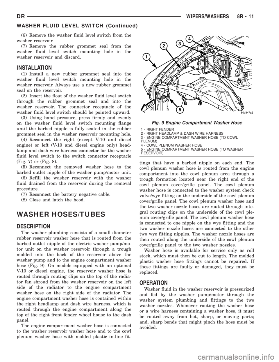
WASHER HOSES/TUBES
DESCRIPTION
The washer plumbing consists of a small diameter
rubber reservoir washer hose that is routed from the
barbed outlet nipple of the electric washer pump/mo-
tor unit on the washer reservoir through a trough
molded into the back of the reservoir above the
washer pump and to the engine compartment washer
hose (Fig. 9). On models equipped with an optional
V-10 or diesel engine, the reservoir washer hose is
routed through routing clips on the top of the radia-
tor fan shroud from the washer reservoir on the left
side of the radiator to the engine compartment
washer hose on the right side of the radiator. The
engine compartment washer hose is contained within
the right headlamp and dash wire harness, which is
routed through the engine compartment along the
top of the right front fender wheel house to the dash
panel.
The engine compartment washer hose is connected
to the washer reservoir washer hose and to the cowl
plenum washer hose with molded plastic in-line fit-tings that have a barbed nipple on each end. The
cowl plenum washer hose is routed from the engine
compartment into the cowl plenum area through a
trough formation located near the right end of the
cowl plenum cover/grille panel. The cowl plenum
washer hose is connected to the washer system check
valve/wye fitting on the underside of the cowl plenum
cover/grille panel. The cowl plenum washer hose and
the two washer nozzle hoses are routed through inte-
gral routing clips on the underside of the cowl ple-
num cover/grille panel. The cowl plenum washer hose
is connected to one nipple on the wye fitting and the
two washer nozzle hoses are connected to the other
two wye fitting nipples. The washer nozzle hoses are
then routed along the underside of the cowl plenum
cover/grille panel to the two washer nozzles.
Washer hose is available for service only as roll
stock, which must then be cut to length. The molded
plastic washer hose fittings cannot be repaired. If
these fittings are faulty or damaged, they must be
replaced.
OPERATION
Washer fluid in the washer reservoir is pressurized
and fed by the washer pump/motor through the
washer system plumbing and fittings to the two
washer nozzles. Whenever routing the washer hose
or a wire harness containing a washer hose, it must
be routed away from hot, sharp, or moving parts;
and, sharp bends that might pinch the hose must be
avoided.
Fig. 9 Engine Compartment Washer Hose
1 - RIGHT FENDER
2 - RIGHT HEADLAMP & DASH WIRE HARNESS
3 - ENGINE COMPARTMENT WASHER HOSE (TO COWL
PLENUM)
4 - COWL PLENUM WASHER HOSE
5 - ENGINE COMPARTMENT WASHER HOSE (TO WASHER
RESERVOIR)
DRWIPERS/WASHERS 8R - 11
WASHER FLUID LEVEL SWITCH (Continued)
Page 688 of 2895
(4) Reinstall the washer hose for the washer noz-
zle into its routing clips on the underside of the cowl
plenum cover/grille panel.
(5) Reinstall the cowl plenum cover/grille panel
over the cowl plenum. (Refer to 23 - BODY/EXTERI-
OR/COWL GRILLE - INSTALLATION).
(6) Close and latch the hood.
(7) Reinstall both wiper arms onto the wiper piv-
ots. (Refer to 8 - ELECTRICAL/WIPERS/WASHERS/
WIPER ARM - INSTALLATION).
WASHER PUMP/MOTOR
DESCRIPTION
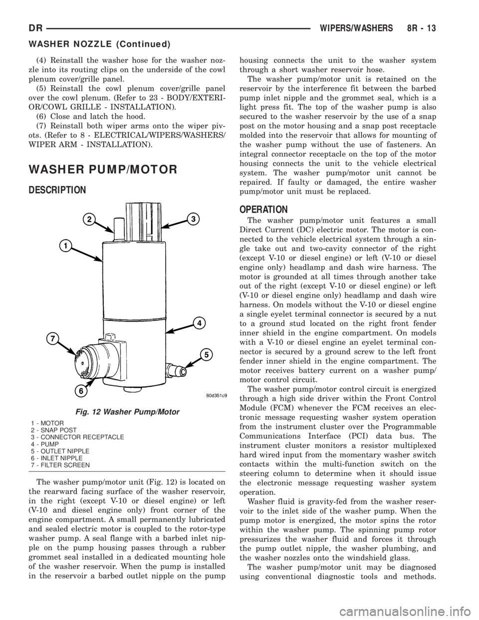
The washer pump/motor unit (Fig. 12) is located on
the rearward facing surface of the washer reservoir,
in the right (except V-10 or diesel engine) or left
(V-10 and diesel engine only) front corner of the
engine compartment. A small permanently lubricated
and sealed electric motor is coupled to the rotor-type
washer pump. A seal flange with a barbed inlet nip-
ple on the pump housing passes through a rubber
grommet seal installed in a dedicated mounting hole
of the washer reservoir. When the pump is installed
in the reservoir a barbed outlet nipple on the pumphousing connects the unit to the washer system
through a short washer reservoir hose.
The washer pump/motor unit is retained on the
reservoir by the interference fit between the barbed
pump inlet nipple and the grommet seal, which is a
light press fit. The top of the washer pump is also
secured to the washer reservoir by the use of a snap
post on the motor housing and a snap post receptacle
molded into the reservoir that allows for mounting of
the washer pump without the use of fasteners. An
integral connector receptacle on the top of the motor
housing connects the unit to the vehicle electrical
system. The washer pump/motor unit cannot be
repaired. If faulty or damaged, the entire washer
pump/motor unit must be replaced.
OPERATION
The washer pump/motor unit features a small
Direct Current (DC) electric motor. The motor is con-
nected to the vehicle electrical system through a sin-
gle take out and two-cavity connector of the right
(except V-10 or diesel engine) or left (V-10 or diesel
engine only) headlamp and dash wire harness. The
motor is grounded at all times through another take
out of the right (except V-10 or diesel engine) or left
(V-10 or diesel engine only) headlamp and dash wire
harness. On models without the V-10 or diesel engine
a single eyelet terminal connector is secured by a nut
to a ground stud located on the right front fender
inner shield in the engine compartment. On models
with a V-10 or diesel engine an eyelet terminal con-
nector is secured by a ground screw to the left front
fender inner shield in the engine compartment. The
motor receives battery current on a washer pump/
motor control circuit.
The washer pump/motor control circuit is energized
through a high side driver within the Front Control
Module (FCM) whenever the FCM receives an elec-
tronic message requesting washer system operation
from the instrument cluster over the Programmable
Communications Interface (PCI) data bus. The
instrument cluster monitors a resistor multiplexed
hard wired input from the momentary washer switch
contacts within the multi-function switch on the
steering column to determine when it should issue
the electronic message requesting washer system
operation.
Washer fluid is gravity-fed from the washer reser-
voir to the inlet side of the washer pump. When the
pump motor is energized, the motor spins the rotor
within the washer pump. The spinning pump rotor
pressurizes the washer fluid and forces it through
the pump outlet nipple, the washer plumbing, and
the washer nozzles onto the windshield glass.
The washer pump/motor unit may be diagnosed
using conventional diagnostic tools and methods.
Fig. 12 Washer Pump/Motor
1 - MOTOR
2 - SNAP POST
3 - CONNECTOR RECEPTACLE
4 - PUMP
5 - OUTLET NIPPLE
6 - INLET NIPPLE
7 - FILTER SCREEN
DRWIPERS/WASHERS 8R - 13
WASHER NOZZLE (Continued)
Page 689 of 2895
However, conventional diagnostic methods may not
prove conclusive in the diagnosis of the instrument
cluster, the Front Control Module (FCM), or the elec-
tronic message inputs to or outputs from the instru-
ment cluster and the FCM that control the operation
of the washer pump/motor unit. The most reliable,
efficient, and accurate means to diagnose the washer
pump/motor unit, the instrument cluster, the FCM,
or the electronic message inputs and outputs related
to the washer pump/motor unit operation requires
the use of a DRBIIItscan tool. Refer to the appro-
priate diagnostic information.
REMOVAL
The washer pump/motor unit can be removed from
the washer reservoir without removing the reservoir
from the vehicle.
(1) Unlatch and open the hood.
(2) Disconnect and isolate the battery negative
cable.
(3) Disconnect the washer hose from the barbed
outlet nipple of the washer pump/motor unit and
allow the washer fluid to drain into a clean container
for reuse.
(4) Disconnect the right (except V-10 or diesel
engine) or left (V-10 or diesel engine only) headlamp
and dash wire harness connector for the washer
pump/motor unit from the motor connector receptacle
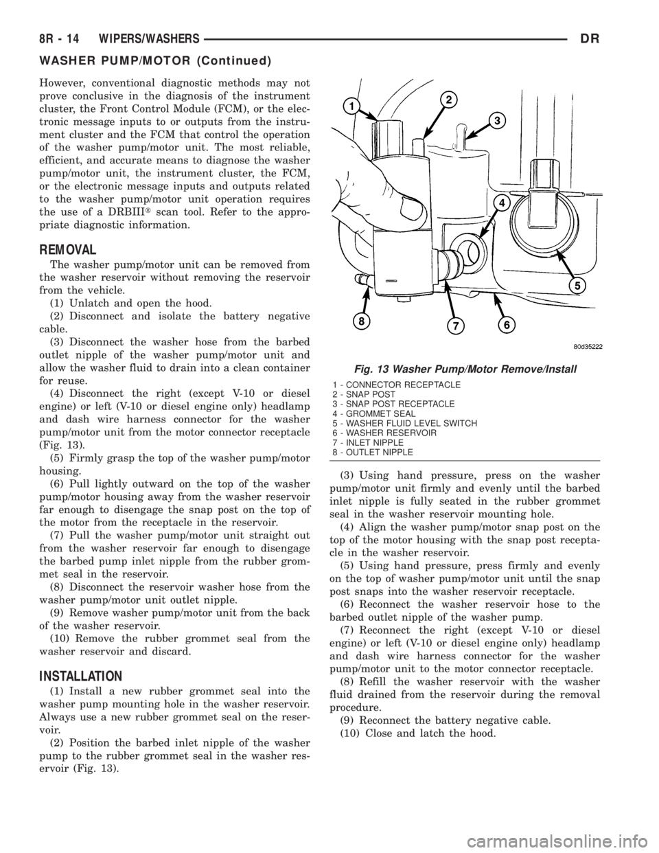
(Fig. 13).
(5) Firmly grasp the top of the washer pump/motor
housing.
(6) Pull lightly outward on the top of the washer
pump/motor housing away from the washer reservoir
far enough to disengage the snap post on the top of
the motor from the receptacle in the reservoir.
(7) Pull the washer pump/motor unit straight out
from the washer reservoir far enough to disengage
the barbed pump inlet nipple from the rubber grom-
met seal in the reservoir.
(8) Disconnect the reservoir washer hose from the
washer pump/motor unit outlet nipple.
(9) Remove washer pump/motor unit from the back
of the washer reservoir.
(10) Remove the rubber grommet seal from the
washer reservoir and discard.
INSTALLATION
(1) Install a new rubber grommet seal into the
washer pump mounting hole in the washer reservoir.
Always use a new rubber grommet seal on the reser-
voir.
(2) Position the barbed inlet nipple of the washer
pump to the rubber grommet seal in the washer res-
ervoir (Fig. 13).(3) Using hand pressure, press on the washer
pump/motor unit firmly and evenly until the barbed
inlet nipple is fully seated in the rubber grommet
seal in the washer reservoir mounting hole.
(4) Align the washer pump/motor snap post on the
top of the motor housing with the snap post recepta-
cle in the washer reservoir.
(5) Using hand pressure, press firmly and evenly
on the top of washer pump/motor unit until the snap
post snaps into the washer reservoir receptacle.
(6) Reconnect the washer reservoir hose to the
barbed outlet nipple of the washer pump.
(7) Reconnect the right (except V-10 or diesel
engine) or left (V-10 or diesel engine only) headlamp
and dash wire harness connector for the washer
pump/motor unit to the motor connector receptacle.
(8) Refill the washer reservoir with the washer
fluid drained from the reservoir during the removal
procedure.
(9) Reconnect the battery negative cable.
(10) Close and latch the hood.
Fig. 13 Washer Pump/Motor Remove/Install
1 - CONNECTOR RECEPTACLE
2 - SNAP POST
3 - SNAP POST RECEPTACLE
4 - GROMMET SEAL
5 - WASHER FLUID LEVEL SWITCH
6 - WASHER RESERVOIR
7 - INLET NIPPLE
8 - OUTLET NIPPLE
8R - 14 WIPERS/WASHERSDR
WASHER PUMP/MOTOR (Continued)
Page 691 of 2895
REMOVAL
REMOVAL - EXCEPT V-10 OR DIESEL ENGINE
(1) Unlatch and open the hood.
(2) Disconnect and isolate the battery negative
cable.
(3) Remove the fasteners securing the coolant
recovery container or the coolant pressure container
to the top of the cooling module and move the con-
tainer aside. It is not necessary to open or drain the
engine cooling system. (Refer to 7 - COOLING/EN-
GINE/COOLANT RECOVERY CONTAINER -
REMOVAL) or (Refer to 7 - COOLING/ENGINE/
COOLANT RECOVERY PRESSURE CONTAINER -
REMOVAL).
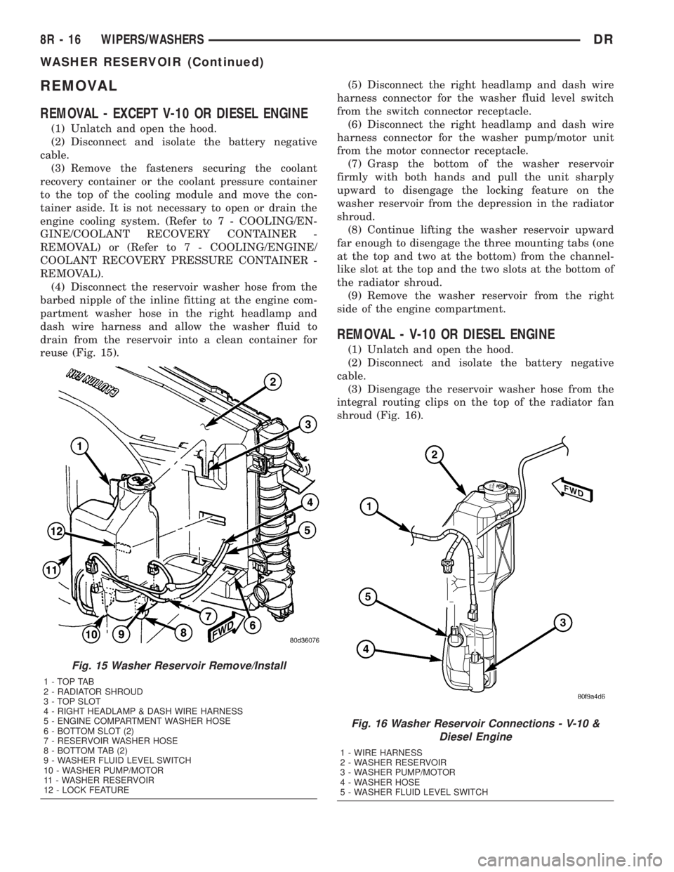
(4) Disconnect the reservoir washer hose from the
barbed nipple of the inline fitting at the engine com-
partment washer hose in the right headlamp and
dash wire harness and allow the washer fluid to
drain from the reservoir into a clean container for
reuse (Fig. 15).(5) Disconnect the right headlamp and dash wire
harness connector for the washer fluid level switch
from the switch connector receptacle.
(6) Disconnect the right headlamp and dash wire
harness connector for the washer pump/motor unit
from the motor connector receptacle.
(7) Grasp the bottom of the washer reservoir
firmly with both hands and pull the unit sharply
upward to disengage the locking feature on the
washer reservoir from the depression in the radiator
shroud.
(8) Continue lifting the washer reservoir upward
far enough to disengage the three mounting tabs (one
at the top and two at the bottom) from the channel-
like slot at the top and the two slots at the bottom of
the radiator shroud.
(9) Remove the washer reservoir from the right
side of the engine compartment.
REMOVAL - V-10 OR DIESEL ENGINE
(1) Unlatch and open the hood.
(2) Disconnect and isolate the battery negative
cable.
(3) Disengage the reservoir washer hose from the
integral routing clips on the top of the radiator fan
shroud (Fig. 16).
Fig. 15 Washer Reservoir Remove/Install
1-TOPTAB
2 - RADIATOR SHROUD
3 - TOP SLOT
4 - RIGHT HEADLAMP & DASH WIRE HARNESS
5 - ENGINE COMPARTMENT WASHER HOSE
6 - BOTTOM SLOT (2)
7 - RESERVOIR WASHER HOSE
8 - BOTTOM TAB (2)
9 - WASHER FLUID LEVEL SWITCH
10 - WASHER PUMP/MOTOR
11 - WASHER RESERVOIR
12 - LOCK FEATURE
Fig. 16 Washer Reservoir Connections - V-10 &
Diesel Engine
1 - WIRE HARNESS
2 - WASHER RESERVOIR
3 - WASHER PUMP/MOTOR
4 - WASHER HOSE
5 - WASHER FLUID LEVEL SWITCH
8R - 16 WIPERS/WASHERSDR
WASHER RESERVOIR (Continued)
Page 692 of 2895
(4) Disconnect the reservoir washer hose from the
barbed nipple of the inline fitting at the engine com-
partment washer hose in the right headlamp and
dash wire harness and allow the washer fluid to
drain from the reservoir into a clean container for
reuse.
(5) Disconnect the left headlamp and dash wire
harness connector for the washer fluid level switch
from the switch connector receptacle.
(6) Disconnect the left headlamp and dash wire
harness connector for the washer pump/motor unit
from the motor connector receptacle.
(7) Remove the two screws that secure the washer
reservoir to the left vertical member of the radiator
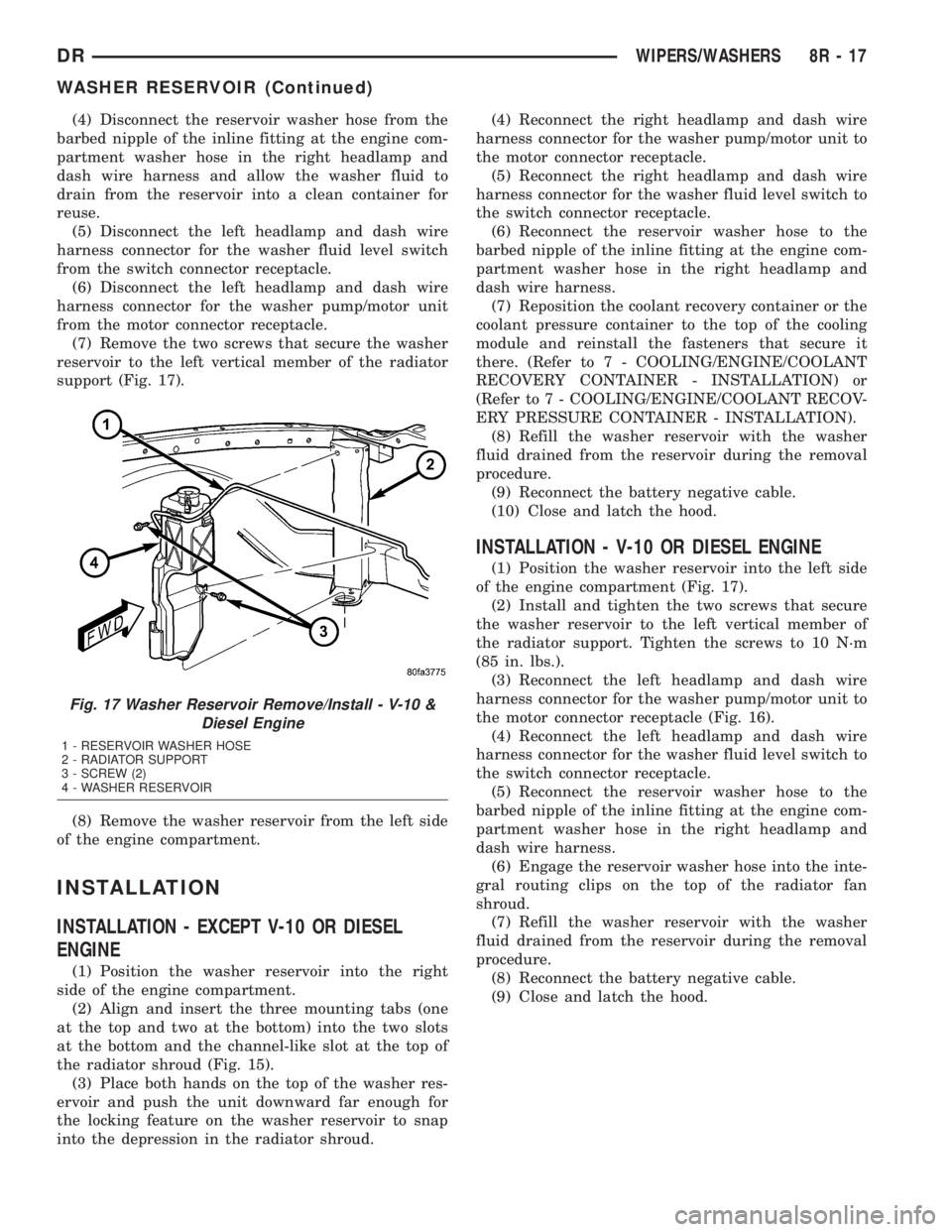
support (Fig. 17).
(8) Remove the washer reservoir from the left side
of the engine compartment.
INSTALLATION
INSTALLATION - EXCEPT V-10 OR DIESEL
ENGINE
(1) Position the washer reservoir into the right
side of the engine compartment.
(2) Align and insert the three mounting tabs (one
at the top and two at the bottom) into the two slots
at the bottom and the channel-like slot at the top of
the radiator shroud (Fig. 15).
(3) Place both hands on the top of the washer res-
ervoir and push the unit downward far enough for
the locking feature on the washer reservoir to snap
into the depression in the radiator shroud.(4) Reconnect the right headlamp and dash wire
harness connector for the washer pump/motor unit to
the motor connector receptacle.
(5) Reconnect the right headlamp and dash wire
harness connector for the washer fluid level switch to
the switch connector receptacle.
(6) Reconnect the reservoir washer hose to the
barbed nipple of the inline fitting at the engine com-
partment washer hose in the right headlamp and
dash wire harness.
(7) Reposition the coolant recovery container or the
coolant pressure container to the top of the cooling
module and reinstall the fasteners that secure it
there. (Refer to 7 - COOLING/ENGINE/COOLANT
RECOVERY CONTAINER - INSTALLATION) or
(Refer to 7 - COOLING/ENGINE/COOLANT RECOV-
ERY PRESSURE CONTAINER - INSTALLATION).
(8) Refill the washer reservoir with the washer
fluid drained from the reservoir during the removal
procedure.
(9) Reconnect the battery negative cable.
(10) Close and latch the hood.
INSTALLATION - V-10 OR DIESEL ENGINE
(1) Position the washer reservoir into the left side
of the engine compartment (Fig. 17).
(2) Install and tighten the two screws that secure
the washer reservoir to the left vertical member of
the radiator support. Tighten the screws to 10 N´m
(85 in. lbs.).
(3) Reconnect the left headlamp and dash wire
harness connector for the washer pump/motor unit to
the motor connector receptacle (Fig. 16).
(4) Reconnect the left headlamp and dash wire
harness connector for the washer fluid level switch to
the switch connector receptacle.
(5) Reconnect the reservoir washer hose to the
barbed nipple of the inline fitting at the engine com-
partment washer hose in the right headlamp and
dash wire harness.
(6) Engage the reservoir washer hose into the inte-
gral routing clips on the top of the radiator fan
shroud.
(7) Refill the washer reservoir with the washer
fluid drained from the reservoir during the removal
procedure.
(8) Reconnect the battery negative cable.
(9) Close and latch the hood.
Fig. 17 Washer Reservoir Remove/Install - V-10 &
Diesel Engine
1 - RESERVOIR WASHER HOSE
2 - RADIATOR SUPPORT
3 - SCREW (2)
4 - WASHER RESERVOIR
DRWIPERS/WASHERS 8R - 17
WASHER RESERVOIR (Continued)