2003 DODGE RAM headlamp
[x] Cancel search: headlampPage 521 of 2895
instrument cluster overlay. The dark outer layer of
the overlay prevents the indicator from being clearly
visible when the it is not illuminated. A blue Light
Emitting Diode (LED) behind the cutout in the
opaque layer of the overlay causes the icon to appear
in blue through the translucent outer layer of the
overlay when the indicator is illuminated from
behind by the LED, which is soldered onto the
instrument cluster electronic circuit board. The high
beam indicator is serviced as a unit with the instru-
ment cluster.
OPERATION
The high beam indicator gives an indication to the
vehicle operator whenever the headlamp high beams
are illuminated. This indicator is controlled by a
transistor on the instrument cluster circuit board
based upon cluster programming and a hard wired
multiplex input received by the cluster from the
headlamp beam select switch circuitry of the multi-
function switch on the washer/beam select switch
mux circuit. The high beam indicator Light Emitting
Diode (LED) is completely controlled by the instru-
ment cluster logic circuit, and that logic will allow
this indicator to operate whenever the instrument
cluster receives a battery current input on the fused
B(+) circuit. Therefore, the LED can be illuminated
regardless of the ignition switch position. The LED
only illuminates when it is provided a path to ground
by the instrument cluster transistor. The instrument
cluster will turn on the high beam indicator for the
following reasons:
²High Beam Headlamps-On Input- Each time
the cluster detects a high beam headlamps-on input
from the headlamp beam select switch circuitry of
the multi-function switch on the washer/beam select
switch mux circuit, the headlamp high beams and
the high beam indicator will be illuminated. The
headlamp high beams and the high beam indicator
remain illuminated until the cluster receives a high
beam headlamps-off input from the multi-function
switch, or until the exterior lamp load shedding (bat-
tery saver) timed interval expires, whichever occurs
first.
²Actuator Test- Each time the cluster is put
through the actuator test, the high beam indicator
will be turned on, then off again during the bulb
check portion of the test to confirm the functionality
of the LED and the cluster control circuitry.
The instrument cluster continually monitors the
headlamp switch and the multi-function switch to
determine the proper headlamp low beam and high
beam control. The instrument cluster then sends the
proper low beam and high beam lamp-on and lamp-
off messages to the Front Control Module (FCM) over
the Programmable Communications Interface (PCI)data bus and turns the high beam indicator on or off
accordingly. For further diagnosis of the high beam
indicator or the instrument cluster circuitry that con-
trols the indicator, (Refer to 8 - ELECTRICAL/IN-
STRUMENT CLUSTER - DIAGNOSIS AND
TESTING). For proper diagnosis of the headlamps, or
the headlamp switch and multi-function switch
inputs to the instrument cluster that control the high
beam indicator, a DRBIIItscan tool is required.
Refer to the appropriate diagnostic information.
LAMP OUT INDICATOR
DESCRIPTION
A lamp out indicator is standard equipment on all
instrument clusters. The lamp out indicator consists
of the words ªLAMP OUTº, which appear in the
lower portion of the odometer/trip odometer Vacuum-
Fluorescent Display (VFD) unit. The VFD is soldered
onto the cluster electronic circuit board and is visible
through a window with a smoked clear lens located
on the lower edge of the tachometer gauge dial face
of the cluster overlay. The dark lens over the VFD
prevents the indicator from being clearly visible
when it is not illuminated. The words ªLAMP OUTº
appear in an amber color and at the same lighting
level as the odometer/trip odometer information
when they are illuminated by the instrument cluster
electronic circuit board. The lamp out indicator is
serviced as a unit with the VFD in the instrument
cluster.
OPERATION
The lamp out indicator gives an indication to the
vehicle operator when an exterior lamp has failed.
This indicator is controlled by the instrument cluster
circuit board based upon cluster programming and
electronic messages received by the cluster from the
Front Control Module (FCM) over the Programmable
Communications Interface (PCI) data bus. The lamp
out indicator is completely controlled by the instru-
ment cluster logic circuit, and that logic will only
allow this indicator to operate when the instrument
cluster receives a battery current input on the fused
ignition switch output (run-start) circuit. Therefore,
the indicator will always be off when the ignition
switch is in any position except On or Start. The
indicator only illuminates when it is switched to
ground by the instrument cluster circuitry. The
instrument cluster will turn on the lamp out indica-
tor for the following reasons:
²Lamp Out Indicator Lamp-On Message-
Each time the cluster receives a lamp out indicator
lamp-on message from the FCM indicating that an
inoperative headlamp (low or high beam), turn signal
8J - 28 INSTRUMENT CLUSTERDR
HIGH BEAM INDICATOR (Continued)
Page 522 of 2895
![DODGE RAM 2003 Service Repair Manual lamp, or brake lamp (excluding Center High
Mounted Stop Lamp [CHMSL]) circuit has been
detected, the lamp out indicator is illuminated. The
indicator remains illuminated until the cluster
receives a l DODGE RAM 2003 Service Repair Manual lamp, or brake lamp (excluding Center High
Mounted Stop Lamp [CHMSL]) circuit has been
detected, the lamp out indicator is illuminated. The
indicator remains illuminated until the cluster
receives a l](/manual-img/12/56913/w960_56913-521.png)
lamp, or brake lamp (excluding Center High
Mounted Stop Lamp [CHMSL]) circuit has been
detected, the lamp out indicator is illuminated. The
indicator remains illuminated until the cluster
receives a lamp out indicator lamp-off message from
the FCM or until the ignition switch is turned to the
Off position, whichever occurs first.
²Actuator Test- Each time the cluster is put
through the actuator test, the lamp out indicator will
be turned on, then off again during the VFD portion
of the test to confirm the functionality of the VFD
and the cluster control circuitry.
The FCM monitors each of the headlamp, turn sig-
nal lamp, and brake lamp (except CHMSL) circuits to
determine the condition of these exterior lamps. The
FCM then sends the proper lamp out indicator
lamp-on and lamp-off messages to the instrument
cluster. For further diagnosis of the lamp out indica-
tor or the instrument cluster circuitry that controls
the indicator, (Refer to 8 - ELECTRICAL/INSTRU-
MENT CLUSTER - DIAGNOSIS AND TESTING).
For proper diagnosis of the exterior lighting system
circuits, the FCM, the PCI data bus, or the electronic
message inputs to the instrument cluster that control
the lamp out indicator, a DRBIIItscan tool is
required. Refer to the appropriate diagnostic infor-
mation.
LOW FUEL INDICATOR
DESCRIPTION
A low fuel indicator is standard equipment on all
instrument clusters. The low fuel indicator is located
on the left side of the instrument cluster, to the left
of the fuel gauge. The low fuel indicator consists of a
stencil-like cutout of the International Control and
Display Symbol icon for ªFuelº in the opaque layer of
the instrument cluster overlay. The dark outer layer
of the overlay prevents the indicator from being
clearly visible when it is not illuminated. An amber
Light Emitting Diode (LED) behind the cutout in the
opaque layer of the overlay causes the icon to appear
in amber through the translucent outer layer of the
overlay when the indicator is illuminated from
behind by the LED, which is soldered onto the
instrument cluster electronic circuit board. The low
fuel indicator is serviced as a unit with the instru-
ment cluster.
OPERATION
The low fuel indicator gives an indication to the
vehicle operator when the level of fuel in the fuel
tank becomes low. This indicator is controlled by a
transistor on the instrument cluster circuit board
based upon cluster programming and electronic mes-sages received by the cluster from the Powertrain
Control Module (PCM) on vehicles equipped with a
gasoline engine, or from the Engine Control Module
(ECM) on vehicles equipped with a diesel engine over
the Programmable Communications Interface (PCI)
data bus. The low fuel indicator Light Emitting
Diode (LED) is completely controlled by the instru-
ment cluster logic circuit, and that logic will only
allow this indicator to operate when the instrument
cluster receives a battery current input on the fused
ignition switch output (run-start) circuit. Therefore,
the LED will always be off when the ignition switch
is in any position except On or Start. The LED only
illuminates when it is provided a path to ground by
the instrument cluster transistor. The instrument
cluster will turn on the low fuel indicator for the fol-
lowing reasons:
²Bulb Test- Each time the ignition switch is
turned to the On position the low fuel indicator is
illuminated for about two seconds as a bulb test.
²Less Than Twenty Percent Tank Full Mes-
sage- Each time the cluster receives messages from
the PCM or ECM indicating the percent tank full is
about twenty percent or less for ten consecutive sec-
onds and the vehicle speed is zero, or for sixty con-
secutive seconds and the vehicle speed is greater
than zero, the fuel gauge needle is moved to the one-
eighth graduation or below on the gauge scale, the
low fuel indicator is illuminated and a single chime
tone is sounded. The low fuel indicator remains illu-
minated until the cluster receives messages from the
PCM or ECM indicating that the percent tank full is
greater than about twenty percent for ten consecu-
tive seconds and the vehicle speed is zero, or for sixty
consecutive seconds and the vehicle speed is greater
than zero, or until the ignition switch is turned to
the Off position, whichever occurs first. The chime
tone feature will only repeat during the same igni-
tion cycle if the low fuel indicator is cycled off and
then on again by the appropriate percent tank full
messages from the PCM or ECM.
²Less Than Empty Percent Tank Full Mes-
sage- Each time the cluster receives a message from
the PCM or ECM indicating the percent tank full is
less than empty, the low fuel indicator is illuminated
immediately. This message would indicate that the
fuel tank sender input to the PCM or ECM is a short
circuit.
²More Than Full Percent Tank Full Message
- Each time the cluster receives a message from the
PCM or ECM indicating the percent tank full is more
than full, the low fuel indicator is illuminated imme-
diately. This message would indicate that the fuel
tank sender input to the PCM or ECM is an open cir-
cuit.
DRINSTRUMENT CLUSTER 8J - 29
LAMP OUT INDICATOR (Continued)
Page 524 of 2895
sions systems may require service. For proper diag-
nosis of the fuel and emissions systems, the PCM,
the ECM, the PCI data bus, or the electronic mes-
sage inputs to the instrument cluster that control the
MIL, a DRBIIItscan tool is required. Refer to the
appropriate diagnostic information.
ODOMETER
DESCRIPTION
An odometer and trip odometer are standard
equipment in all instrument clusters. The odometer,
trip odometer, and engine hours information are dis-
played in a common electronic, blue-green Vacuum-
Fluorescent Display (VFD). The VFD is soldered onto
the cluster electronic circuit board and is visible
through a window with a smoked clear lens located
on the lower edge of the tachometer gauge dial face
of the cluster overlay. The dark lens over the VFD
prevents it from being clearly visible when it is not
illuminated. However, the odometer, trip odometer,
and engine hours information are not displayed
simultaneously. The trip odometer reset switch on
the instrument cluster circuit board toggles the dis-
play between odometer and trip odometer modes by
depressing the odometer/trip odometer switch button
that extends through the lower edge of the cluster
lens, just left of the odometer VFD. When the trip
odometer information is displayed, the word ªTRIPº
is also illuminated in the upper right corner of the
VFD in a blue-green color and at the same lighting
level as the trip odometer information. The engine
hours information replaces the selected odometer or
trip odometer information whenever the ignition
switch is in the On position and the engine is not
running.
The odometer, trip odometer, and engine hours
information is stored in the instrument cluster mem-
ory. This information can be increased when the
proper inputs are provided to the instrument cluster,
but the information cannot be decreased. The odom-
eter can display values up to 999,999 kilometers
(999,999 miles). The odometer latches at these val-
ues, and will not roll over to zero. The trip odometer
can display values up to 9,999.9 kilometers (9,999.9
miles) before it rolls over to zero. The odometer dis-
play does not have a decimal point and will not show
values less than a full unit (kilometer or mile), while
the trip odometer display does have a decimal point
and will show tenths of a unit (kilometer or mile).
The unit of measure (kilometers or miles) for the
odometer and trip odometer display is not shown in
the VFD. The unit of measure for the instrument
cluster odometer/trip odometer is selected at the time
that it is manufactured, and cannot be changed.Engine hours are displayed in the format, ªhr9999º.
The cluster will accumulate values up to 9,999 hours
before the display rolls over to zero.
The odometer has a ªRental Carº mode, which will
illuminate the odometer information in the VFD
whenever the driver side front door is opened with
the ignition switch in the Off or Accessory positions.
During daylight hours (exterior lamps are Off) the
VFD is illuminated at full brightness for clear visibil-
ity. At night (exterior lamps are On) the VFD lighting
level is adjusted with the other cluster illumination
lamps using the panel lamps dimmer thumbwheel on
the headlamp switch. However, a ªParadeº mode
position of the panel lamps dimmer thumbwheel
allows the VFD to be illuminated at full brightness if
the exterior lamps are turned On during daylight
hours.
The VFD, the trip odometer switch, and the trip
odometer switch button are serviced as a unit with
the instrument cluster.
OPERATION
The odometer and trip odometer give an indication
to the vehicle operator of the distance the vehicle has
traveled. The engine hours give an indication of the
cumulative engine-on time. This indicator is con-
trolled by the instrument cluster circuitry based
upon cluster programming and electronic messages
received by the cluster from the Powertrain Control
Module (PCM) over the Programmable Communica-
tions Interface (PCI) data bus. The odometer, trip
odometer and engine hours information is displayed
by the instrument cluster Vacuum Fluorescent Dis-
play (VFD). The VFD will display the odometer infor-
mation whenever any door is opened with the
ignition switch in the Off or Accessory positions, and
will display the last previously selected odometer or
trip odometer information when the ignition switch is
turned to the On or Start positions. The instrument
cluster circuitry controls the VFD and provides the
following features:
²Odometer/Trip Odometer Display Toggling-
Actuating the trip odometer reset switch button
momentarily with the VFD illuminated will toggle
the display between the odometer and trip odometer
information. Each time the VFD is illuminated with
the ignition switch in the On or Start positions, the
display will automatically return to the last mode
previously selected (odometer or trip odometer).
²Engine Hours Display Toggling- When the
trip odometer reset switch button is pressed and held
for longer than about six seconds with the ignition
switch in the On position and the engine speed mes-
sage from the PCM is zero, the trip odometer infor-
mation will be momentarily displayed, then the
engine hours information will be displayed. The VFD
DRINSTRUMENT CLUSTER 8J - 31
MALFUNCTION INDICATOR LAMP (MIL) (Continued)
Page 538 of 2895
LAMPS
TABLE OF CONTENTS
page page
LAMPS/LIGHTING - EXTERIOR............... 1LAMPS/LIGHTING - INTERIOR............... 24
LAMPS/LIGHTING - EXTERIOR
TABLE OF CONTENTS
page page
LAMPS/LIGHTING - EXTERIOR
DESCRIPTION..........................2
OPERATION............................2
DIAGNOSIS AND TESTING - LAMPS/
LIGHTING - EXTERIOR..................3
STANDARD PROCEDURE
SAFETY PRECAUTIONS.................7
SPECIFICATIONS
EXTERIOR LAMPS.....................7
SPECIAL TOOLS - HEADLAMP ALIGNMENT . . . 7
BACKUP LAMP
REMOVAL.............................7
INSTALLATION..........................7
BACKUP LAMP SWITCH
DESCRIPTION..........................7
OPERATION............................8
DIAGNOSIS AND TESTING - BACKUP LAMP
SWITCH.............................8
BRAKE LAMP
REMOVAL.............................8
INSTALLATION..........................8
BRAKE LAMP SWITCH
DESCRIPTION..........................8
OPERATION............................8
DIAGNOSIS AND TESTING - BRAKE LAMP
SWITCH.............................9
REMOVAL.............................9
INSTALLATION.........................10
CENTER HIGH MOUNTED STOP LAMP
REMOVAL.............................10
INSTALLATION.........................10
CENTER HIGH MOUNTED STOP LAMP UNIT
REMOVAL.............................10
INSTALLATION.........................10
CAB CLEARANCE LAMP
REMOVAL.............................10
INSTALLATION.........................10FOG LAMP
REMOVAL.............................11
INSTALLATION.........................11
FOG LAMP RELAY
DESCRIPTION.........................11
OPERATION...........................12
DIAGNOSIS AND TESTING - FRONT FOG
LAMP RELAY.........................12
REMOVAL.............................13
INSTALLATION.........................13
HAZARD SWITCH
DESCRIPTION.........................13
OPERATION...........................13
HEADLAMP
REMOVAL.............................13
INSTALLATION.........................13
HEADLAMP SWITCH
DESCRIPTION.........................14
OPERATION...........................14
REMOVAL.............................14
INSTALLATION.........................14
HEADLAMP UNIT
REMOVAL.............................15
INSTALLATION.........................15
ADJUSTMENTS........................15
LICENSE PLATE LAMP
REMOVAL.............................16
INSTALLATION.........................16
LICENSE PLATE LAMP UNIT
REMOVAL.............................16
INSTALLATION.........................16
MARKER LAMP UNIT
REMOVAL
REMOVAL...........................16
REMOVAL...........................16
INSTALLATION
INSTALLATION.......................17
INSTALLATION.......................17
DRLAMPS 8L - 1
Page 539 of 2895
MULTI-FUNCTION SWITCH
DESCRIPTION - TURN SIGNAL SYSTEM.....17
OPERATION - TURN SIGNAL SYSTEM.......18
DIAGNOSIS AND TESTING - MULTI-
FUNCTION SWITCH...................18
REMOVAL.............................18
INSTALLATION.........................19
PARK LAMP RELAY
DESCRIPTION.........................19
OPERATION...........................19
DIAGNOSIS AND TESTING - PARK LAMP
RELAY..............................20
REMOVAL.............................20
INSTALLATION.........................21
PARK/TURN SIGNAL LAMP
REMOVAL.............................21
INSTALLATION.........................21TAIL LAMP
REMOVAL.............................21
INSTALLATION.........................21
TAIL LAMP UNIT
REMOVAL.............................21
INSTALLATION.........................21
TRAILER TOW WIRING
DESCRIPTION.........................22
TURN LAMP
REMOVAL.............................22
INSTALLATION.........................22
UNDERHOOD LAMP
REMOVAL.............................22
INSTALLATION.........................22
UNDERHOOD LAMP UNIT
REMOVAL.............................22
INSTALLATION.........................23
LAMPS/LIGHTING - EXTERIOR
DESCRIPTION
The exterior lighting system for this model include
the following components:
²Backup Lamps
²Brake Lamps
²Daytime Running Lamps
²Front Fog Lamps
²Hazard Warning Lamps
²Headlamps
²Park Lamps
²Turn Signal Lamps
Other components of the exterior lighting system
for this model include:
²Backup Lamp Switch
²Brake Lamp Switch
²Front Control Module
²Front Fog Lamp Relay
²Hazard Switch
²Multi-Function Switch
²Park Lamp Relay
²Trailer Tow Connectors
Some of the interior and exterior lighting functions
are governed by the front control module. The head-
lamp, dome, and door ajar switchs provide signals to
the instrument cluster. The instrument cluster sends
a J1850 message to the front control module to
enable the necessary components for illumination.
Hard wired circuitry connects the exterior lighting
system components to the electrical system of the
vehicle. Refer to the appropriate wiring information.
OPERATION
DAYTIME RUNNING LAMPS
Power is reduced using pulse-width modulation to
the high beams, where by the power is switched on
and off rapidly instead of remaining on continuously.
The duration and interval of the power pulses is pro-
grammed into the Front Control Module (FCM).
HEADLAMP SYSTEM
The instrument cluster monitors both the multi-
plexed headlamp and multifunction switches. The
instrument cluster transmits a J1850 bus message to
the front control module (FCM) to activate the head-
lamps. The headlamp system will default to head-
lamps ON position when ignition switch is ON and
when an open or short circuit failure occurs on the
headlamp switch input to the instrument cluster. The
system will return to normal operation when the
open or short is repaired. A fault will be reported by
the Instrument Cluster when a failure occurs on the
dimmer or headlamp switch input.
If the exterior lamps are ON, and the headlamp
switch is in any position other than OFF, with the
ignition switch OFF (LOCK) after 5 minutes, the
Instrument Cluster transmits a message via J1850
informing the the FCM. The FCM will then turn off
the headlamps, park lamps and fog lamps. This fea-
ture (load shed) prevents the vehicle battery from
being discharged when the vehicle lights have been
left ON.
HEADLAMP TIME DELAY SYSTEM
The headlamp time delay system is activated by
turning the headlamps ON (high or low beam) while
the engine is running, turning the ignition switch
OFF, and then turning the headlamp switch OFF
8L - 2 LAMPS/LIGHTING - EXTERIORDR
Page 540 of 2895
within 45 seconds. The system will not activate if
more than 45 seconds elapse between ignition switch
OFF and headlamp switch OFF. The FCM will allow
the headlamps to remain ON for 60 seconds (config-
urable) before they automatically turn off (If the key
is in the ignition during the headlamp time delay
mode, then the headlamps including panel dimming
will be ON).
LAMP OUTAGE
If one or more of the following lamps (Low and/or
High beams, Brake and/or Turn Signal) are out, then
a ªlamps outº indicator located in the cluster will
illuminate.
OPTICAL HORN/HIGH BEAMS
When the multiplexed multifunction switch is
pulled to the first detent (optical horn) signal, the
headlamps are ON, the Instrument Cluster shall
send a message via J1850 to the FCM to turn on the
headlamps drivers to illuminate all four filaments
(Low and High beams). When the multifunction
switch is pulled to the second detent (high beam) sig-
nal and the headlamps are ON, the Instrument Clus-
ter shall send a message via J1850 to the FCM to
turn on the headlamps drivers. The High Beams are
illuminated and the Low Beams and Fog Lamps (if
ON) are extinguished. If the headlamps were in the
high beam configuration when power was removed
from the headlamps, the headlamps will return to
their last state prior to being shut off.
DIAGNOSIS AND TESTING - LAMPS/LIGHTING
- EXTERIOR
WARNING: EYE PROTECTION SHOULD BE USED
WHEN SERVICING GLASS COMPONENTS. PER-
SONAL INJURY CAN RESULT.
CAUTION: Do not touch the glass of halogen bulbs
with fingers or other possibly oily surface, reduced
bulb life will result. Do not use bulbs other than
those indicated in the Bulb Application table. Dam-
age to lamp and/or Daytime Running Lamp Module
can result. Do not use fuses, circuit breakers or
relays having greater amperage value than indi-
cated on the fuse panel or in the Owners Manual.
When a vehicle experiences problems with the
headlamp system, verify the condition of the battery
connections, fuses, charging system, headlamp bulbs,
wire connectors, relay, multifunction switch, and
headlamp switch. Refer to the appropriate wiring
information.
Each vehicle is equipped with various lamp assem-
blies. A good ground is necessary for proper lighting
operation. Grounding is provided by the lamp socket
when it comes in contact with the metal body, or
through a separate ground wire.
When changing lamp bulbs check the socket for
loose pin connections and corrosion. Repair as neces-
sary.
When it is necessary to remove components to ser-
vice another, it should not be necessary to apply
excessive force or bend a component to remove it.
Before damaging a trim component, verify hidden
fasteners or captured edges are not holding the com-
ponent in place.
DRLAMPS/LIGHTING - EXTERIOR 8L - 3
LAMPS/LIGHTING - EXTERIOR (Continued)
Page 541 of 2895
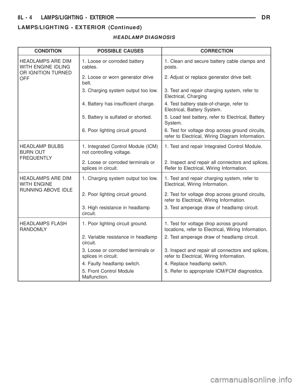
HEADLAMP DIAGNOSIS
CONDITION POSSIBLE CAUSES CORRECTION
HEADLAMPS ARE DIM
WITH ENGINE IDLING
OR IGNITION TURNED
OFF1. Loose or corroded battery
cables.1. Clean and secure battery cable clamps and
posts.
2. Loose or worn generator drive
belt.2. Adjust or replace generator drive belt.
3. Charging system output too low. 3. Test and repair charging system, refer to
Electrical, Charging
4. Battery has insufficient charge. 4. Test battery state-of-charge, refer to
Electrical, Battery System.
5. Battery is sulfated or shorted. 5. Load test battery, refer to Electrical, Battery
System.
6. Poor lighting circuit ground. 6. Test for voltage drop across ground circuits,
refer to Electrical, Wiring Diagram Information.
HEADLAMP BULBS
BURN OUT
FREQUENTLY1. Integrated Control Module (ICM)
not controlling voltage.1. Test and repair Integrated Control Module.
2. Loose or corroded terminals or
splices in circuit.2. Inspect and repair all connectors and splices.
Refer to Electrical, Wiring Information.
HEADLAMPS ARE DIM
WITH ENGINE
RUNNING ABOVE IDLE1. Charging system output too low. 1. Test and repair charging system, refer to
Electrical, Wiring Information.
2. Poor lighting circuit ground. 2. Test for voltage drop across ground circuits,
refer to Electrical, Wiring Information.
3. High resistance in headlamp
circuit.3. Test amperage draw of headlamp circuit.
HEADLAMPS FLASH
RANDOMLY1. Poor lighting circuit ground. 1. Test for voltage drop across ground
locations, refer to Electrical, Wiring Information.
2. Variable resistance in headlamp
circuit.2. Test amperage draw of headlamp circuit.
3. Loose or corroded terminals or
splices in circuit.3. Inspect and repair all connectors and splices,
refer to Electrical, Wiring Information.
4. Faulty headlamp switch. 4. Replace headlamp switch.
5. Front Control Module
Malfunction.5. Refer to appropriate ICM/FCM diagnostics.
8L - 4 LAMPS/LIGHTING - EXTERIORDR
LAMPS/LIGHTING - EXTERIOR (Continued)
Page 542 of 2895
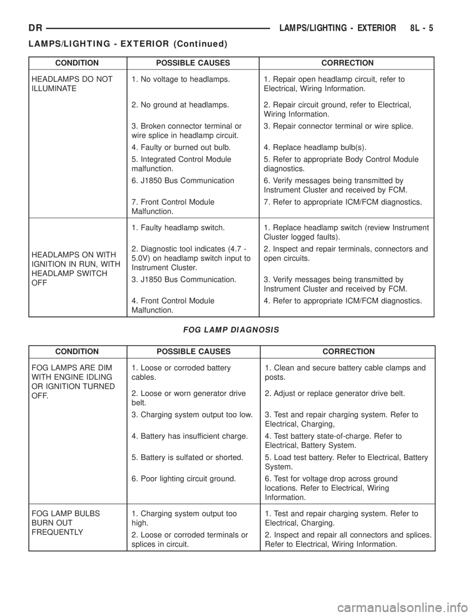
CONDITION POSSIBLE CAUSES CORRECTION
HEADLAMPS DO NOT
ILLUMINATE1. No voltage to headlamps. 1. Repair open headlamp circuit, refer to
Electrical, Wiring Information.
2. No ground at headlamps. 2. Repair circuit ground, refer to Electrical,
Wiring Information.
3. Broken connector terminal or
wire splice in headlamp circuit.3. Repair connector terminal or wire splice.
4. Faulty or burned out bulb. 4. Replace headlamp bulb(s).
5. Integrated Control Module
malfunction.5. Refer to appropriate Body Control Module
diagnostics.
6. J1850 Bus Communication 6. Verify messages being transmitted by
Instrument Cluster and received by FCM.
7. Front Control Module
Malfunction.7. Refer to appropriate ICM/FCM diagnostics.
HEADLAMPS ON WITH
IGNITION IN RUN, WITH
HEADLAMP SWITCH
OFF1. Faulty headlamp switch. 1. Replace headlamp switch (review Instrument
Cluster logged faults).
2. Diagnostic tool indicates (4.7 -
5.0V) on headlamp switch input to
Instrument Cluster.2. Inspect and repair terminals, connectors and
open circuits.
3. J1850 Bus Communication. 3. Verify messages being transmitted by
Instrument Cluster and received by FCM.
4. Front Control Module
Malfunction.4. Refer to appropriate ICM/FCM diagnostics.
FOG LAMP DIAGNOSIS
CONDITION POSSIBLE CAUSES CORRECTION
FOG LAMPS ARE DIM
WITH ENGINE IDLING
OR IGNITION TURNED
OFF.1. Loose or corroded battery
cables.1. Clean and secure battery cable clamps and
posts.
2. Loose or worn generator drive
belt.2. Adjust or replace generator drive belt.
3. Charging system output too low. 3. Test and repair charging system. Refer to
Electrical, Charging,
4. Battery has insufficient charge. 4. Test battery state-of-charge. Refer to
Electrical, Battery System.
5. Battery is sulfated or shorted. 5. Load test battery. Refer to Electrical, Battery
System.
6. Poor lighting circuit ground. 6. Test for voltage drop across ground
locations. Refer to Electrical, Wiring
Information.
FOG LAMP BULBS
BURN OUT
FREQUENTLY1. Charging system output too
high.1. Test and repair charging system. Refer to
Electrical, Charging.
2. Loose or corroded terminals or
splices in circuit.2. Inspect and repair all connectors and splices.
Refer to Electrical, Wiring Information.
DRLAMPS/LIGHTING - EXTERIOR 8L - 5
LAMPS/LIGHTING - EXTERIOR (Continued)