2003 DODGE RAM headlamp
[x] Cancel search: headlampPage 1147 of 2895
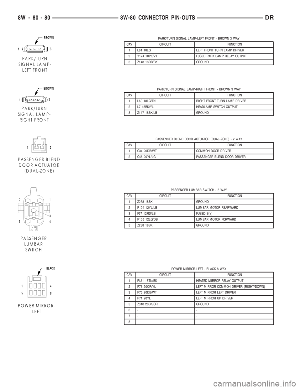
PARK/TURN SIGNAL LAMP-LEFT FRONT - BROWN 3 WAY
CAV CIRCUIT FUNCTION
1 L61 18LG LEFT FRONT TURN LAMP DRIVER
2 Y174 18PK/VT FUSED PARK LAMP RELAY OUTPUT
3 Z148 18DB/BK GROUND
PARK/TURN SIGNAL LAMP-RIGHT FRONT - BROWN 3 WAY
CAV CIRCUIT FUNCTION
1 L60 18LG/TN RIGHT FRONT TURN LAMP DRIVER
2 L7 18BK/YL HEADLAMP SWITCH OUTPUT
3 Z147 18BK/LB GROUND
PASSENGER BLEND DOOR ACTUATOR (DUAL-ZONE)-2WAY
CAV CIRCUIT FUNCTION
1 C34 20DB/WT COMMON DOOR DRIVER
2 C46 20YL/LG PASSENGER BLEND DOOR DRIVER
PASSENGER LUMBAR SWITCH-5WAY
CAV CIRCUIT FUNCTION
1 Z238 18BK GROUND
2 P104 12YL/LB LUMBAR MOTOR REARWARD
3 F37 12RD/LB FUSED B(+)
4 P105 12LG/DB LUMBAR MOTOR FORWARD
5 Z238 18BK GROUND
POWER MIRROR-LEFT - BLACK 8 WAY
CAV CIRCUIT FUNCTION
1 F121 18TN/BK HEATED MIRROR RELAY OUTPUT
2 P76 20OR/YL LEFT MIRROR COMMON DRIVER (RIGHT/DOWN)
3 P75 20DB/WT LEFT MIRROR LEFT DRIVER
4 P71 20YL LEFT MIRROR UP DRIVER
5 Z310 20BK/OR GROUND
6- -
7- -
8- -
8W - 80 - 80 8W-80 CONNECTOR PIN-OUTSDR
Page 1166 of 2895
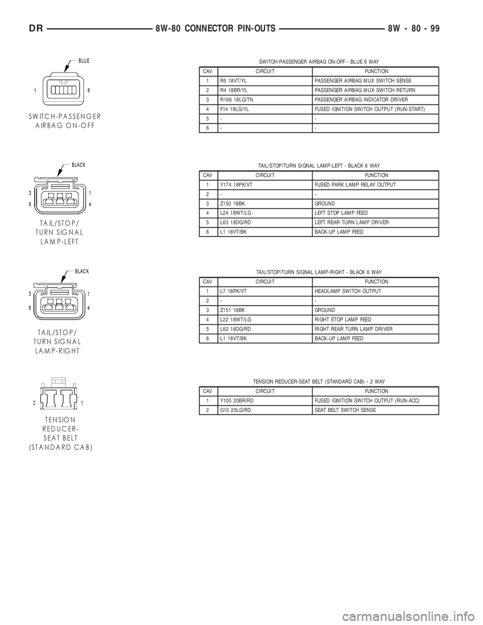
SWITCH-PASSENGER AIRBAG ON-OFF - BLUE 6 WAY
CAV CIRCUIT FUNCTION
1 R5 18VT/YL PASSENGER AIRBAG MUX SWITCH SENSE
2 R4 18BR/YL PASSENGER AIRBAG MUX SWITCH RETURN
3 R166 18LG/TN PASSENGER AIRBAG INDICATOR DRIVER
4 F14 18LG/YL FUSED IGNITION SWITCH OUTPUT (RUN-START)
5- -
6- -
TAIL/STOP/TURN SIGNAL LAMP-LEFT - BLACK 6 WAY
CAV CIRCUIT FUNCTION
1 Y174 18PK/VT FUSED PARK LAMP RELAY OUTPUT
2- -
3 Z150 18BK GROUND
4 L24 18WT/LG LEFT STOP LAMP FEED
5 L63 18DG/RD LEFT REAR TURN LAMP DRIVER
6 L1 18VT/BK BACK-UP LAMP FEED
TAIL/STOP/TURN SIGNAL LAMP-RIGHT - BLACK 6 WAY
CAV CIRCUIT FUNCTION
1 L7 18PK/VT HEADLAMP SWITCH OUTPUT
2- -
3 Z151 18BK GROUND
4 L22 18WT/LG RIGHT STOP LAMP FEED
5 L62 18DG/RD RIGHT REAR TURN LAMP DRIVER
6 L1 18VT/BK BACK-UP LAMP FEED
TENSION REDUCER-SEAT BELT (STANDARD CAB)-2WAY
CAV CIRCUIT FUNCTION
1 Y105 20BR/RD FUSED IGNITION SWITCH OUTPUT (RUN-ACC)
2 G10 20LG/RD SEAT BELT SWITCH SENSE
DR8W-80 CONNECTOR PIN-OUTS 8W - 80 - 99
Page 1181 of 2895
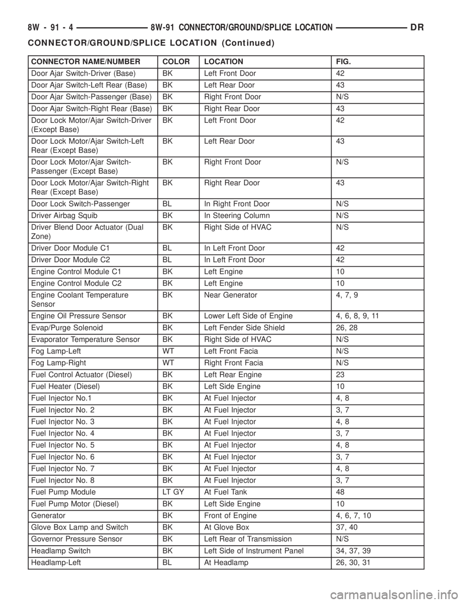
CONNECTOR NAME/NUMBER COLOR LOCATION FIG.
Door Ajar Switch-Driver (Base) BK Left Front Door 42
Door Ajar Switch-Left Rear (Base) BK Left Rear Door 43
Door Ajar Switch-Passenger (Base) BK Right Front Door N/S
Door Ajar Switch-Right Rear (Base) BK Right Rear Door 43
Door Lock Motor/Ajar Switch-Driver
(Except Base)BK Left Front Door 42
Door Lock Motor/Ajar Switch-Left
Rear (Except Base)BK Left Rear Door 43
Door Lock Motor/Ajar Switch-
Passenger (Except Base)BK Right Front Door N/S
Door Lock Motor/Ajar Switch-Right
Rear (Except Base)BK Right Rear Door 43
Door Lock Switch-Passenger BL In Right Front Door N/S
Driver Airbag Squib BK In Steering Column N/S
Driver Blend Door Actuator (Dual
Zone)BK Right Side of HVAC N/S
Driver Door Module C1 BL In Left Front Door 42
Driver Door Module C2 BL In Left Front Door 42
Engine Control Module C1 BK Left Engine 10
Engine Control Module C2 BK Left Engine 10
Engine Coolant Temperature
SensorBK Near Generator 4, 7, 9
Engine Oil Pressure Sensor BK Lower Left Side of Engine 4, 6, 8, 9, 11
Evap/Purge Solenoid BK Left Fender Side Shield 26, 28
Evaporator Temperature Sensor BK Right Side of HVAC N/S
Fog Lamp-Left WT Left Front Facia N/S
Fog Lamp-Right WT Right Front Facia N/S
Fuel Control Actuator (Diesel) BK Left Rear Engine 23
Fuel Heater (Diesel) BK Left Side Engine 10
Fuel Injector No.1 BK At Fuel Injector 4, 8
Fuel Injector No. 2 BK At Fuel Injector 3, 7
Fuel Injector No. 3 BK At Fuel Injector 4, 8
Fuel Injector No. 4 BK At Fuel Injector 3, 7
Fuel Injector No. 5 BK At Fuel Injector 4, 8
Fuel Injector No. 6 BK At Fuel Injector 3, 7
Fuel Injector No. 7 BK At Fuel Injector 4, 8
Fuel Injector No. 8 BK At Fuel Injector 3, 7
Fuel Pump Module LT GY At Fuel Tank 48
Fuel Pump Motor (Diesel) BK Left Side Engine 10
Generator BK Front of Engine 4, 6, 7, 10
Glove Box Lamp and Switch BK At Glove Box 37, 40
Governor Pressure Sensor BK Left Rear of Transmission N/S
Headlamp Switch BK Left Side of Instrument Panel 34, 37, 39
Headlamp-Left BL At Headlamp 26, 30, 31
8W - 91 - 4 8W-91 CONNECTOR/GROUND/SPLICE LOCATIONDR
CONNECTOR/GROUND/SPLICE LOCATION (Continued)
Page 1182 of 2895
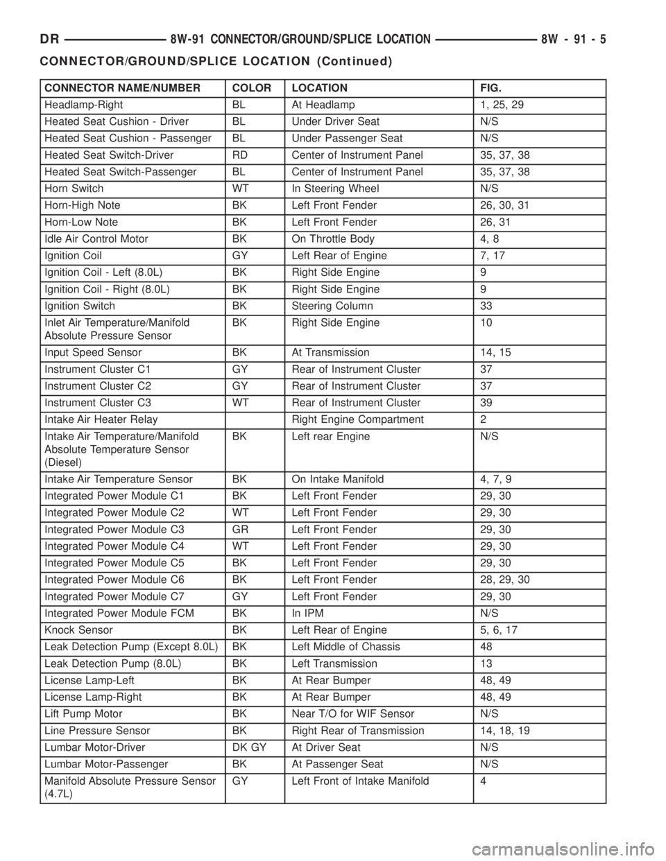
CONNECTOR NAME/NUMBER COLOR LOCATION FIG.
Headlamp-Right BL At Headlamp 1, 25, 29
Heated Seat Cushion - Driver BL Under Driver Seat N/S
Heated Seat Cushion - Passenger BL Under Passenger Seat N/S
Heated Seat Switch-Driver RD Center of Instrument Panel 35, 37, 38
Heated Seat Switch-Passenger BL Center of Instrument Panel 35, 37, 38
Horn Switch WT In Steering Wheel N/S
Horn-High Note BK Left Front Fender 26, 30, 31
Horn-Low Note BK Left Front Fender 26, 31
Idle Air Control Motor BK On Throttle Body 4, 8
Ignition Coil GY Left Rear of Engine 7, 17
Ignition Coil - Left (8.0L) BK Right Side Engine 9
Ignition Coil - Right (8.0L) BK Right Side Engine 9
Ignition Switch BK Steering Column 33
Inlet Air Temperature/Manifold
Absolute Pressure SensorBK Right Side Engine 10
Input Speed Sensor BK At Transmission 14, 15
Instrument Cluster C1 GY Rear of Instrument Cluster 37
Instrument Cluster C2 GY Rear of Instrument Cluster 37
Instrument Cluster C3 WT Rear of Instrument Cluster 39
Intake Air Heater Relay Right Engine Compartment 2
Intake Air Temperature/Manifold
Absolute Temperature Sensor
(Diesel)BK Left rear Engine N/S
Intake Air Temperature Sensor BK On Intake Manifold 4, 7, 9
Integrated Power Module C1 BK Left Front Fender 29, 30
Integrated Power Module C2 WT Left Front Fender 29, 30
Integrated Power Module C3 GR Left Front Fender 29, 30
Integrated Power Module C4 WT Left Front Fender 29, 30
Integrated Power Module C5 BK Left Front Fender 29, 30
Integrated Power Module C6 BK Left Front Fender 28, 29, 30
Integrated Power Module C7 GY Left Front Fender 29, 30
Integrated Power Module FCM BK In IPM N/S
Knock Sensor BK Left Rear of Engine 5, 6, 17
Leak Detection Pump (Except 8.0L) BK Left Middle of Chassis 48
Leak Detection Pump (8.0L) BK Left Transmission 13
License Lamp-Left BK At Rear Bumper 48, 49
License Lamp-Right BK At Rear Bumper 48, 49
Lift Pump Motor BK Near T/O for WIF Sensor N/S
Line Pressure Sensor BK Right Rear of Transmission 14, 18, 19
Lumbar Motor-Driver DK GY At Driver Seat N/S
Lumbar Motor-Passenger BK At Passenger Seat N/S
Manifold Absolute Pressure Sensor
(4.7L)GY Left Front of Intake Manifold 4
DR8W-91 CONNECTOR/GROUND/SPLICE LOCATION 8W - 91 - 5
CONNECTOR/GROUND/SPLICE LOCATION (Continued)
Page 1186 of 2895
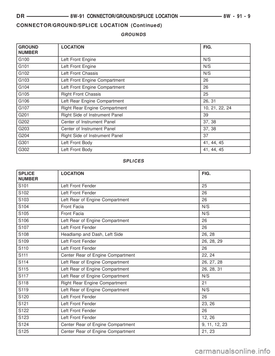
GROUNDS
GROUND
NUMBERLOCATION FIG.
G100 Left Front Engine N/S
G101 Left Front Engine N/S
G102 Left Front Chassis N/S
G103 Left Front Engine Compartment 26
G104 Left Front Engine Compartment 26
G105 Right Front Chassis 25
G106 Left Rear Engine Compartment 26, 31
G107 Right Rear Engine Compartment 10, 21, 22, 24
G201 Right Side of Instrument Panel 39
G202 Center of Instrument Panel 37, 38
G203 Center of Instrument Panel 37, 38
G204 Right Side of Instrument Panel 37
G301 Left Front Body 41, 44, 45
G302 Left Front Body 41, 44, 45
SPLICES
SPLICE
NUMBERLOCATION FIG.
S101 Left Front Fender 25
S102 Left Front Fender 26
S103 Left Rear of Engine Compartment 26
S104 Front Facia N/S
S105 Front Facia N/S
S106 Left Rear of Engine Compartment 26
S107 Left Front Fender 26
S108 Headlamp and Dash, Left Side 26, 28
S109 Left Front Fender 26, 28, 29
S110 Left Front Fender 26
S111 Center Rear of Engine Compartment 22, 24
S114 Left Rear of Engine Compartment 26, 27, 28
S115 Left Rear of Engine Compartment 26, 28, 31
S117 Left Rear of Engine Compartment N/S
S118 Right Rear Engine Compartment 21
S119 Left Rear of Engine Compartment N/S
S120 Left Front Fender 26
S121 Left Front Fender 23, 26
S122 Left Front Fender 26
S123 Left Front Fender 12, 26
S124 Center Rear of Engine Compartment 9, 11, 12, 23
S125 Center Rear of Engine Compartment 21, 23
DR8W-91 CONNECTOR/GROUND/SPLICE LOCATION 8W - 91 - 9
CONNECTOR/GROUND/SPLICE LOCATION (Continued)
Page 1187 of 2895
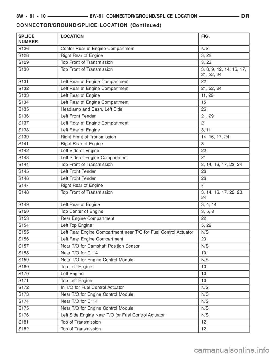
SPLICE
NUMBERLOCATION FIG.
S126 Center Rear of Engine Compartment N/S
S128 Right Rear of Engine 3, 22
S129 Top Front of Transmission 3, 23
S130 Top Front of Transmission 3, 8, 9, 12, 14, 16, 17,
21, 22, 24
S131 Left Rear of Engine Compartment 22
S132 Left Rear of Engine Compartment 21, 22, 24
S133 Left Rear of Engine 11, 22
S134 Left Rear of Engine Compartment 15
S135 Headlamp and Dash, Left Side 26
S136 Left Front Fender 21, 29
S137 Left Rear of Engine Compartment 21
S138 Left Rear of Engine 3, 11
S139 Right Front of Transmission 14, 16, 17, 24
S141 Right Rear of Engine 3
S142 Left Side of Engine 22
S143 Left Side of Engine Compartment 21
S144 Top Front of Transmission 3, 14, 16, 17, 23, 24
S145 Left Front Fender 26
S146 Left Front Fender 26
S147 Right Rear of Engine 7
S148 Top Front of Transmission 3, 14, 16, 17, 22, 23,
24
S149 Left Rear of Engine 3, 4, 14
S150 Top Center of Engine 3, 5, 8
S153 Rear Engine Compartment 22
S154 Left Top Engine 5, 22
S155 Left Rear Engine Compartment near T/O for Fuel Control Actuator N/S
S156 Left Rear Engine Compartment 23
S157 Near T/O for Camshaft Position Sensor N/S
S158 Near T/O for C114 10
S159 Near T/O for Engine Control Module N/S
S160 Top Left Engine 10
S170 Left Engine 10
S171 Top Left Engine 10
S172 In T/O for Fuel Control Actuator N/S
S173 Near T/O for Engine Control Module N/S
S174 Near T/O for C114 N/S
S175 Near T/O for Engine Control Module N/S
S176 Left Side Engine Near T/O for Fuel Control Actuator N/S
S181 Top of Transmission 12
S182 Top of Transmission 12
8W - 91 - 10 8W-91 CONNECTOR/GROUND/SPLICE LOCATIONDR
CONNECTOR/GROUND/SPLICE LOCATION (Continued)
Page 1244 of 2895
tery and provides the primary means of circuit pro-
tection and power distribution for all vehicle
electrical systems. The front control module controls
power to some of these vehicle systems electrical and
electromechanical loads based on inputs received
from hard wired switch inputs and data received on
the PCI bus circuit (J1850).
For information on theIntegrated Power Mod-
ule Refer to the Power Distribution Sectionof
the service manual.
OPERATION
As messages are sent over the PCI bus circuit, the
front control module reads these messages and con-
trols power to some of the vehicles electrical systems
by completing the circuit to ground (low side driver)
or completing the circuit to 12 volt power (high side
driver). The following functions areControlledby
the Front Control Module:
²Headlamp Power with Voltage Regulation
²Windshield Wiper ªON/OFFº Relay Actuation
²Windshield Wiper ªHI/LOº Relay Actuation
²Windshield Washer Pump Motor
²Fog Lamp Relay Actuation
²Park Lamp Relay Actuation
²Horn Relay Actuation
The following inputs areReceived/Monitoredby
the Front Control Module:
²B+ Connection Detection²Power Ground
²Ambient Temperature Sensing
²Ignition Switch Run
²Washer Fluid Level Switch
²Windshield Wiper Park Switch
²PCI Bus Circuit
DIAGNOSIS AND TESTING - FRONT CONTROL
MODULE
The front control module is a printed circuit board
based module with a on-board micro-processor. The
front control module interfaces with other electronic
modules in the vehicle via the Programmable Com-
munications Interface (PCI) data bus (J1850). In
order to obtain conclusive testing the Programmable
Communications Interface (PCI) data bus network
and all of the electronic modules that provide inputs
to, or receive outputs from the front control module
must be checked. All PCI (J1850) communication
faults must be resolved prior to further diagnosing
any front control module related issues.
The front control module was designed to be diag-
nosed with an appropriate diagnostic scan tool, such
as the DRB IIIt. The most reliable, efficient, and
accurate means to diagnose the front control module
requires the use of a DRB IIItscan tool and the
proper Body Diagnostic Procedures manual.
Before any testing of the front control module is
attempted, the battery should be fully charged and
all wire harness and ground connections inspected
around the affected areas on the vehicle.
REMOVAL
(1) Disconnect the positive and negative battery
cables from the battery.
(2) Partially remove the integrated power module
from the engine compartment (Refer to 8 - ELECTRI-
CAL/POWER DISTRIBUTION/INTEGRATED
POWER MODULE - REMOVAL).
(3)
Remove the front control module retaining
screws.
(4) Using both hands, pull the front control module
straightfrom the integrated power module assembly
to disconnect the 49-way electrical connector and
remove the front control module from the vehicle.
INSTALLATION
(1) Install the front control module on the inte-
grated power module assembly by pushing the
49-way electrical connector straight in.
(2) Install the front control module retaining
screws. Torque the screws to 7 in. lbs.
(3) Install the integrated power module (Refer to 8
- ELECTRICAL/POWER DISTRIBUTION/INTE-
GRATED POWER MODULE - INSTALLATION).
(4)
Connect the positive and negative battery cables.
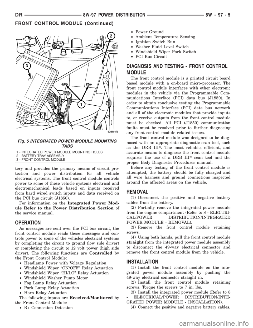
Fig. 5 INTEGRATED POWER MODULE MOUNTING
TABS
1 - INTEGRATED POWER MODULE MOUNTING HOLES
2 - BATTERY TRAY ASSEMBLY
3 - FRONT CONTROL MODULE
DR8W-97 POWER DISTRIBUTION 8W - 97 - 5
FRONT CONTROL MODULE (Continued)
Page 1683 of 2895
STANDARD PROCEDURE - HYDROFORM
FENDER RAIL REPAIR
SAFETY PRECAUTIONS AND WARNINGS
WARNING: USE EYE PROTECTION WHEN GRIND-
ING OR WELDING METAL, SERIOUS EYE INJURY
CAN RESULT.
²BEFORE PROCEEDING WITH FRAME REPAIR
INVOLVING GRINDING OR WELDING, VERIFY THAT
VEHICLE FUEL SYSTEM IS NOT LEAKING OR IN
CONTACT WITH REPAIR AREA, PERSONAL INJURY
CAN RESULT.
²DO NOT ALLOW OPEN FLAME OR HEAT AND
METAL SPATTER FROM ARC WELDING, TO CON-
TACT PLASTIC BODY PANELS. FIRE OR EXPLO-
SION CAN RESULT.
²WHEN WELDED FRAME COMPONENTS ARE
REPLACED, ENSURE COMPLETE PENETRATION
WELD IS ACHIEVED DURING INSTALLATION. IF
NOT, DANGEROUS OPERATING CONDITIONS CAN
RESULT.
²STAND CLEAR OF CABLES OR CHAINS ON
PULLING EQUIPMENT DURING FRAME STRAIGHT-
ENING OPERATIONS, PERSONAL INJURY CAN
RESULT.
²DO NOT VENTURE UNDER A HOISTED VEHI-
CLE THAT IS NOT SUPPORTED ON SAFETY
STANDS, PERSONAL INJURY CAN RESULT.
CAUTION: Do not reuse damaged fasteners, quality
of repair would be suspect. Failure to use only pro-
duction fasteners or fasteners of equivalent hard-
ness can result in loosening or failure. Do not drill
holes in top or bottom frame rail flanges, frame rail
failure can result. When using heat to straighten
frame components do not exceed 566ÉC (1050ÉF),
metal fatigue can result.
CAUTION: This repair procedure assumes damage
to the right or left hydroform fender rail (Fig. 19).
Prior to any repairs, the vehicle must be mounted
on the appropriate frame repair equipment (ªframe
rackº), checked with three dimensional measuring
equipment, and necessary pull corrections made. If
damage exists in the hydroform fender rail, or cab
beyond the area covered by this service procedure
after dimensional corrections are made, the hydro-
form must be replaced in its entirety. Refer to 23 -
BODY/BODY STRUCTURE/WELD LOCATIONS -
SPECIFICATIONS, when replacing the entire hydro-
form.(1) Disconnect and isolate the battery negative
cable.
(2) Remove the front wheelhouse splash shield.
(Refer to 23 - BODY/EXTERIOR/FRONT WHEEL-
HOUSE SPLASH SHIELD - REMOVAL)
(3) Remove the fender. (Refer to 23 - BODY/EXTE-
RIOR/FRONT FENDER - REMOVAL)
(4) Remove the A/C condenser, if required. (Refer
to 24 - HEATING & AIR CONDITIONING/PLUMB-
ING/A/C CONDENSER - REMOVAL)
(5) Remove the A/C lines, if required. Refer to the
Heating and Air Conditioning section of the manual
for recommended procedures.
(6) Remove the radiator assembly. (Refer to 7 -
COOLING/ENGINE/RADIATOR - REMOVAL)
(7) Remove the air cleaner and support bracket, if
required. (Refer to 9 - ENGINE/AIR INTAKE SYS-
TEM/AIR CLEANER ELEMENT - REMOVAL)
(8) Remove the integrated power module. (Refer to
8 - ELECTRICAL/POWER DISTRIBUTION/INTE-
GRATED POWER MODULE - REMOVAL)
(9) Remove the bolts and position aside the wire
harness and grounds, if required.
(10) Remove the upper radiator crossmember.
(Refer to 23 - BODY/EXTERIOR/UPPER RADIATOR
CROSSMEMBER - REMOVAL)
(11) Remove the headlamp unit. (Refer to 8 -
ELECTRICAL/LAMPS/LIGHTING - EXTERIOR/
HEADLAMP UNIT - REMOVAL)
(12) Remove the front cab mount to the Front End
Sheet Metal bracket (FESM) bolt.
(13) Remove the bolts attaching the lower radiator
crossmember to the hydroform fender rail. (Fig. 19)
CAUTION: Do not use any flame or plasma cutting
equipment to cut the frame in this procedure. The
inaccurate and high temperatures achieved during
flame or plasma cutting will change the metal char-
acteristics and may weaken the frame and/or repair
location.
(14) Using a reciprocating saw or equivalent, cut
the fender rail and shotgun at a straight and square
section of the hydroform and remove.
(15) Smooth and square the cut edges.
(16) Using the damaged structure as a reference
cut the service part at the same location as the first
cut. Smooth and square the cut edges.
NOTE: The repair structure should butt up to the
remaining structure and provide the same overall
vehicle geometry.
13 - 12 FRAMES & BUMPERSDR
FRAME (Continued)