2003 DODGE RAM fuse diagram
[x] Cancel search: fuse diagramPage 2788 of 2895

NOTE: The air gap is determined by the spacer
shims. When installing an original, or a new clutch
assembly, try the original shims first. When install-
ing a new clutch onto a compressor that previously
did not have a clutch, use a 1.0, 0.50, and 0.13 mil-
limeter (0.040, 0.020, and 0.005 inch) shims from the
new clutch hardware package that is provided with
the new clutch.
(9) To complete the procedure, (Refer to 24 -
HEATING & AIR CONDITIONING/PLUMBING/A/C
COMPRESSOR - INSTALLATION).
A/C COMPRESSOR CLUTCH
RELAY
DESCRIPTION
The compressor clutch relay is a International
Standards Organization (ISO) micro-relay. The termi-
nal designations and functions are the same as a con-
ventional ISO relay. However, the micro-relay
terminal orientation (footprint) is different, the cur-
rent capacity is lower, and the relay case dimensions
are smaller than those of the conventional ISO relay.
The compressor clutch relay is located in the Power
Distribution Center (PDC) in the engine compart-
ment. Refer to the PDC label for relay identification
and location.
OPERATION
The compressor clutch relay is a electromechanical
device that switches battery current to the compres-
sor clutch coil when the Powertrain Control Module
(PCM) grounds the coil side of the relay. The PCM
responds to inputs from the A/C Heater mode control
switch, the A/C low pressure switch, and the A/C
high pressure switch. (Refer to 24 - HEATING & AIR
CONDITIONING/CONTROLS/A/C COMPRESSOR
CLUTCH RELAY - DIAGNOSIS AND TESTING)
The compressor clutch relay cannot be repaired
and, if faulty or damaged, it must be replaced.
DIAGNOSIS AND TESTING - COMPRESSOR
CLUTCH RELAY
RELAY TEST
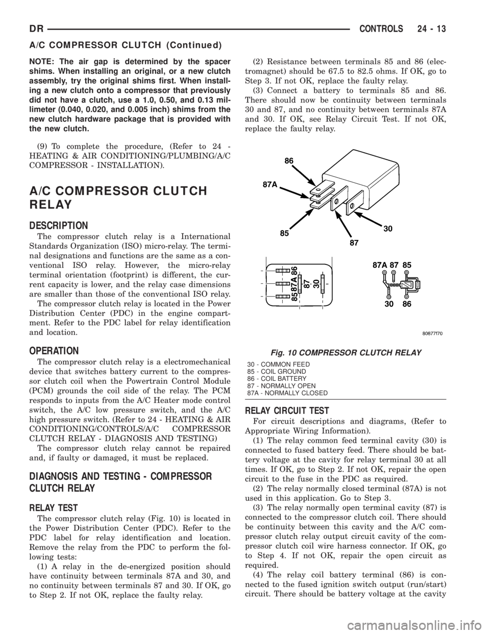
The compressor clutch relay (Fig. 10) is located in
the Power Distribution Center (PDC). Refer to the
PDC label for relay identification and location.
Remove the relay from the PDC to perform the fol-
lowing tests:
(1) A relay in the de-energized position should
have continuity between terminals 87A and 30, and
no continuity between terminals 87 and 30. If OK, go
to Step 2. If not OK, replace the faulty relay.(2) Resistance between terminals 85 and 86 (elec-
tromagnet) should be 67.5 to 82.5 ohms. If OK, go to
Step 3. If not OK, replace the faulty relay.
(3) Connect a battery to terminals 85 and 86.
There should now be continuity between terminals
30 and 87, and no continuity between terminals 87A
and 30. If OK, see Relay Circuit Test. If not OK,
replace the faulty relay.
RELAY CIRCUIT TEST
For circuit descriptions and diagrams, (Refer to
Appropriate Wiring Information).
(1) The relay common feed terminal cavity (30) is
connected to fused battery feed. There should be bat-
tery voltage at the cavity for relay terminal 30 at all
times. If OK, go to Step 2. If not OK, repair the open
circuit to the fuse in the PDC as required.
(2) The relay normally closed terminal (87A) is not
used in this application. Go to Step 3.
(3) The relay normally open terminal cavity (87) is
connected to the compressor clutch coil. There should
be continuity between this cavity and the A/C com-
pressor clutch relay output circuit cavity of the com-
pressor clutch coil wire harness connector. If OK, go
to Step 4. If not OK, repair the open circuit as
required.
(4) The relay coil battery terminal (86) is con-
nected to the fused ignition switch output (run/start)
circuit. There should be battery voltage at the cavity
Fig. 10 COMPRESSOR CLUTCH RELAY
30 - COMMON FEED
85 - COIL GROUND
86 - COIL BATTERY
87 - NORMALLY OPEN
87A - NORMALLY CLOSED
DRCONTROLS 24 - 13
A/C COMPRESSOR CLUTCH (Continued)
Page 2801 of 2895

DIAGNOSIS AND TESTING - BLOWER MOTOR
WARNING: ON VEHICLES EQUIPPED WITH AIR-
BAGS, DISABLE THE AIRBAG SYSTEM BEFORE
ATTEMPTING ANY STEERING WHEEL, STEERING
COLUMN, OR INSTRUMENT PANEL COMPONENT
DIAGNOSIS OR SERVICE. DISCONNECT AND ISO-
LATE THE BATTERY NEGATIVE (GROUND) CABLE,
THEN WAIT TWO MINUTES FOR THE AIRBAG SYS-
TEM CAPACITOR TO DISCHARGE BEFORE PER-
FORMING FURTHER DIAGNOSIS OR SERVICE. THIS
IS THE ONLY SURE WAY TO DISABLE THE AIRBAG
SYSTEM. FAILURE TO TAKE THE PROPER PRE-
CAUTIONS COULD RESULT IN AN ACCIDENTAL
AIRBAG DEPLOYMENT AND POSSIBLE PERSONAL
INJURY.
For circuit descriptions and diagrams, (Refer to
Appropriate Wiring Information). Possible causes of
an inoperative blower motor include:
²Faulty fuse
²Faulty blower motor circuit wiring or wire har-
ness connectors
²Faulty blower motor resistor
²Faulty blower motor relay
²Faulty blower motor switch
²Faulty A/C Heater mode control switch
²Faulty blower motor.
Possible causes of the blower motor not operating
in all speeds include:
²Faulty blower motor switch
²Faulty blower motor resistor
²Faulty blower motor circuit wiring or wire har-
ness connectors.
VIBRATION
Possible causes of blower motor vibration include:
²Improper blower motor mounting
²Improper blower wheel mounting
²Blower wheel out of balance or bent
²Blower motor faulty.
NOISE
To verify that the blower is the source of the noise,
unplug the blower motor wire harness connector and
operate the HVAC system. If the noise goes away,
possible causes include:
²Foreign material in the HVAC housing
²Improper blower motor mounting
²Improper blower wheel mounting
²Blower motor faulty.
REMOVAL
WARNING: ON VEHICLES EQUIPPED WITH AIR-
BAGS, DISABLE THE AIRBAG SYSTEM BEFORE
ATTEMPTING ANY STEERING WHEEL, STEERINGCOLUMN, OR INSTRUMENT PANEL COMPONENT
DIAGNOSIS OR SERVICE. DISCONNECT AND ISO-
LATE THE BATTERY NEGATIVE (GROUND) CABLE,
THEN WAIT TWO MINUTES FOR THE AIRBAG SYS-
TEM CAPACITOR TO DISCHARGE BEFORE PER-
FORMING FURTHER DIAGNOSIS OR SERVICE. THIS
IS THE ONLY SURE WAY TO DISABLE THE AIRBAG
SYSTEM. FAILURE TO TAKE THE PROPER PRE-
CAUTIONS COULD RESULT IN AN ACCIDENTAL
AIRBAG DEPLOYMENT AND POSSIBLE PERSONAL
INJURY.
The blower motor is located on the passenger side
of the vehicle under the dash
(1) Disconnect and isolate the battery negative
cable.
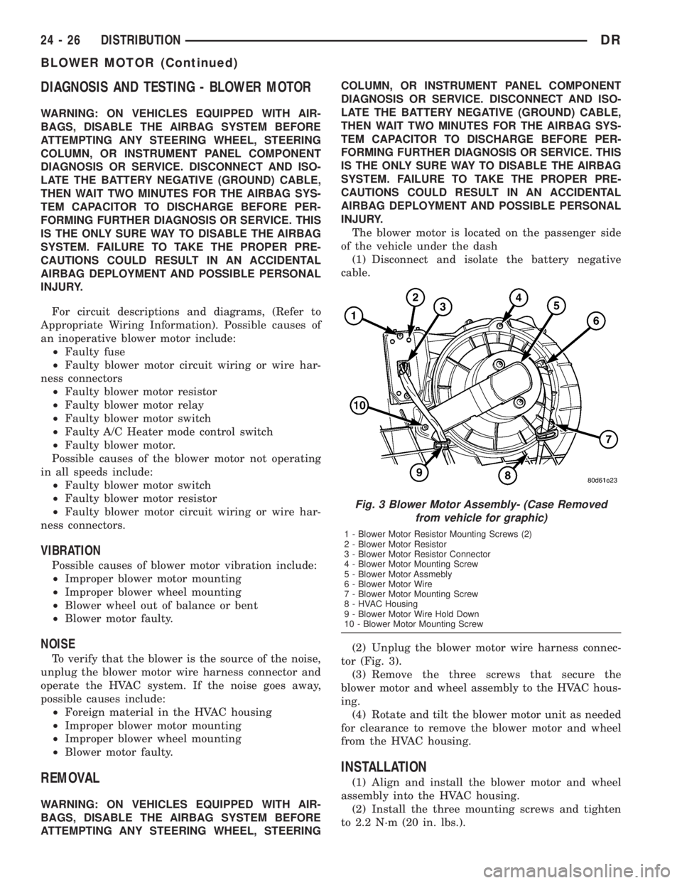
(2) Unplug the blower motor wire harness connec-
tor (Fig. 3).
(3) Remove the three screws that secure the
blower motor and wheel assembly to the HVAC hous-
ing.
(4) Rotate and tilt the blower motor unit as needed
for clearance to remove the blower motor and wheel
from the HVAC housing.
INSTALLATION
(1) Align and install the blower motor and wheel
assembly into the HVAC housing.
(2) Install the three mounting screws and tighten
to 2.2 N´m (20 in. lbs.).
Fig. 3 Blower Motor Assembly- (Case Removed
from vehicle for graphic)
1 - Blower Motor Resistor Mounting Screws (2)
2 - Blower Motor Resistor
3 - Blower Motor Resistor Connector
4 - Blower Motor Mounting Screw
5 - Blower Motor Assmebly
6 - Blower Motor Wire
7 - Blower Motor Mounting Screw
8 - HVAC Housing
9 - Blower Motor Wire Hold Down
10 - Blower Motor Mounting Screw
24 - 26 DISTRIBUTIONDR
BLOWER MOTOR (Continued)
Page 2890 of 2895

TIRE REVOLUTIONS PER MILE,
SPECIFICATIONS.....................22-10
TIRE ROTATION - STANDARD
PROCEDURE.........................22-2
TIRE WEAR PATTERNS - DIAGNOSIS
AND TESTING........................22-8
TIRES - DESCRIPTION.................22-5
TIRES - DESCRIPTION, RADIAL - PLY.....22-6
TIRES - DESCRIPTION, REPLACEMENT....22-6
TIRE/VEHICLE LEAD - DIAGNOSIS AND
TESTING............................22-8
TO COOLER - INSTALLATION, RETURN
HOSE - GEAR..................19-43,19-44
TO COOLER - INSTALLATION, RETURN
HOSE - RESERVOIR.............19-43,19-44
TO COOLER - REMOVAL, RETURN HOSE
- GEAR............................19-43
TO COOLER - REMOVAL, RETURN HOSE
- RESERVOIR..................19-43,19-44
TO GROUND - STANDARD PROCEDURE,
TESTING FOR A SHORT.............8W-01-9
TO GROUND ON FUSES POWERING
SEVERAL LOADS - STANDARD
PROCEDURE, TESTING FOR A SHORT . 8W-01-10
TO OIL COOLER - INSTALLATION, AIR.....7-75
TO OIL COOLER - REMOVAL, AIR.........7-74
TO OIL COOLER - REMOVAL, WATER......7-74
TO USE WIRING DIAGRAMS -
DESCRIPTION, HOW................8W-01-1
TOE ADJUSTMENT - STANDARD
PROCEDURE..........................2-4
TOE ADJUSTMENT - STANDARD
PROCEDURE, CAMBER, CASTER..........2-4
TOOL - ADJUSTMENT, WITH ADJUSTING . . . 5-36
TOOLS - 4.7L ENGINE, SPECIAL.........9-102
TOOLS - 5.7L ENGINE, SPECIAL.........9-192
TOOLS - 5.9L DIESEL ENGINE, SPECIAL . . 9-294
TOOLS - 5.9L ENGINE, SPECIAL.........9-240
TOOLS - 8.0L ENGINE, SPECIAL.........9-367
TOOLS - 9 1/4 AA, SPECIAL.............2-29
TOOLS - BASE BRAKES, SPECIAL.........5-5
TOOLS - BATTERY SYSTEM SPECIAL
TOOLS, SPECIAL......................8F-7
TOOLS - BODY, SPECIAL...............23-14
TOOLS - COOLING, SPECIAL.............7-20
TOOLS - DIESEL FUEL SYSTEM,
SPECIAL...........................14-60
TOOLS - FRONT SUSPENSION, SPECIAL . . . 2-11
TOOLS - FUEL SYSTEM, SPECIAL........14-5
TOOLS - OVERHEAD CONSOLE, SPECIAL . . 8M-6
TOOLS - POWER DISTRIBUTION
SYSTEMS, SPECIAL................8W-97-2
TOOLS - POWER STEERING GEAR,
SPECIAL...........................19-22
TOOLS - RE TRANSMISSION, SPECIAL . . 21-189,
21-370
TOOLS - RFE TRANSMISSION, SPECIAL . . 21-535
TOOLS - STEERING LINKAGE, SPECIAL . . . 19-35
TOOLS - STEERING, SPECIAL............19-5
TOOLS - TRANSFER CASE NV271/NV273,
SPECIAL....................21-650,21-714
TOOLS - WHEEL ALIGNMENT, SPECIAL.....2-7
TOOLS - WIRING/TERMINAL, SPECIAL . 8W-01-10
TOOLS, DIAGNOSIS AND TESTING -
SPECIAL............................11-4
TOOLS, FRONT AXLE - 9 1/4 AA -
SPECIAL............................3-53
TOOLS, FRONT AXLE - C205F - SPECIAL . . . 3-30
TOOLS, HALF SHAFT - SPECIAL..........3-12
TOOLS, HEADLAMP ALIGNMENT -
SPECIAL............................8L-7
TOOLS, MANUAL TRANSMISSION -
NV3500 - SPECIAL...................21-40
TOOLS, MANUAL TRANSMISSION -
NV4500 - SPECIAL...................21-79
TOOLS, MANUAL TRANSMISSION -
NV5600 - SPECIAL..................21-122
TOOLS, PROPELLER SHAFT - SPECIAL.....3-6
TOOLS, REAR AXLE - 10 1/2 AA -
SPECIAL...........................3-108
TOOLS, REAR AXLE - 11 1/2 AA -
SPECIAL
...........................3-135
TOOLS, REAR AXLE - 9 1/4 - SPECIAL
.....3-80
TOOLS, SPECIAL TOOLS - BATTERY
SYSTEM SPECIAL
.....................8F-7
TOOLS, SPECIFICATIONS - SPECIAL
.......9-16
TOP COVER - INSTALLATION,
INSTRUMENT PANEL
..................23-60TOP COVER - REMOVAL, INSTRUMENT
PANEL.............................23-59
TORSION BAR - DESCRIPTION...........2-25
TORSION BAR - INSTALLATION..........2-26
TORSION BAR - OPERATION.............2-25
TORSION BAR - REMOVAL..............2-25
TORSION BAR CROSS MEMBER
BUSHING - INSTALLATION..............2-14
TORSION BAR CROSSMEMBER
BUSHING - REMOVAL..................2-12
TOUCH-UP - DESCRIPTION, PAINT.......23-75
TOUCH-UP - STANDARD PROCEDURE,
PAINT.............................23-75
TOW HOOK ASSEMBLY - INSTALLATION,
FRONT.............................13-26
TOW HOOK ASSEMBLY - REMOVAL,
FRONT.............................13-26
TOW WIRING - DESCRIPTION, TRAILER . . 8L-22
TOWING - STANDARD PROCEDURE.......0-15
TRACK - DESCRIPTION, POWER SEAT....8N-18
TRACK - DIAGNOSIS AND TESTING,
POWER SEAT.......................8N-18
TRACK - INSTALLATION, POWER SEAT . . . 8N-19
TRACK - INSTALLATION, SEAT..........23-83
TRACK - OPERATION, POWER SEAT.....8N-18
TRACK - REMOVAL, POWER SEAT.......8N-19
TRACK - REMOVAL, SEAT..............23-83
TRACK BAR - INSTALLATION...........19-37
TRACK BAR - REMOVAL................19-37
TRAC-RITE - ASSEMBLY, DIFFERENTIAL . . 3-120,
3-147
TRAC-RITE - CLEANING, DIFFERENTIAL . . 3-119,
3-146
TRAC-RITE - DESCRIPTION,
DIFFERENTIAL..................3-118,3-145
TRAC-RITE - DISASSEMBLY,
DIFFERENTIAL..................3-118,3-145
TRAC-RITE - INSPECTION, DIFFERENTIAL . 3-119,
3-146
TRAC-RITE - OPERATION, DIFFERENTIAL . 3-118,
3-145
TRAILER HITCH - INSTALLATION........13-25
TRAILER HITCH - REMOVAL............13-25
TRAILER TOW WIRING - DESCRIPTION . . . 8L-22
TRANS COOLER - 5.9L DIESEL -
DESCRIPTION........................7-73
TRANS COOLER - 5.9L DIESEL -
OPERATION..........................7-74
TRANS TEMP INDICATOR -
DESCRIPTION.......................8J-38
TRANS TEMP INDICATOR - OPERATION . . . 8J-38
TRANSDUCER - DESCRIPTION, A/C
PRESSURE.........................24-15
TRANSDUCER - DIAGNOSIS AND
TESTING, A/C PRESSURE..............24-15
TRANSDUCER - INSTALLATION, A/C
PRESSURE.........................24-16
TRANSDUCER - OPERATION, A/C
PRESSURE.........................24-15
TRANSDUCER - REMOVAL, A/C
PRESSURE.........................24-16
TRANSFER CASE - NV241 GENII -
ASSEMBLY.........................21-604
TRANSFER CASE - NV241 GENII -
CLEANING
.........................21-602
TRANSFER CASE - NV241 GENII -
DESCRIPTION
.........................0-4
TRANSFER CASE - NV241 GENII -
DESCRIPTION
......................21-591
TRANSFER CASE - NV241 GENII -
DIAGNOSIS AND TESTING
............21-592
TRANSFER CASE - NV241 GENII -
DISASSEMBLY
......................21-593
TRANSFER CASE - NV241 GENII -
INSPECTION
.......................21-602
TRANSFER CASE - NV241 GENII -
INSTALLATION
......................21-614
TRANSFER CASE - NV241 GENII -
OPERATION
........................21-591
TRANSFER CASE - NV241 GENII -
REMOVAL
.........................21-593
TRANSFER CASE - NV243 - ASSEMBLY
. . 21-670
TRANSFER CASE - NV243 - CLEANING
. . 21-668
TRANSFER CASE - NV243 -
DESCRIPTION
.........................0-4
TRANSFER CASE - NV243 -
DESCRIPTION
......................21-658TRANSFER CASE - NV243 - DIAGNOSIS
AND TESTING......................21-659
TRANSFER CASE - NV243 -
DISASSEMBLY......................21-660
TRANSFER CASE - NV243 - INSPECTION . 21-668
TRANSFER CASE - NV243 -
INSTALLATION......................21-679
TRANSFER CASE - NV243 - OPERATION . 21-659
TRANSFER CASE - NV243 - REMOVAL . . . 21-660
TRANSFER CASE - NV271 - ASSEMBLY . . 21-637
TRANSFER CASE - NV271 - CLEANING . . 21-635
TRANSFER CASE - NV271 -
DESCRIPTION.........................0-4
TRANSFER CASE - NV271 -
DESCRIPTION......................21-623
TRANSFER CASE - NV271 - DIAGNOSIS
AND TESTING......................21-624
TRANSFER CASE - NV271 -
DISASSEMBLY......................21-625
TRANSFER CASE - NV271 - INSPECTION . 21-635
TRANSFER CASE - NV271 -
INSTALLATION......................21-649
TRANSFER CASE - NV271 - OPERATION . 21-623
TRANSFER CASE - NV271 - REMOVAL . . . 21-625
TRANSFER CASE - NV273 - ASSEMBLY . . 21-701
TRANSFER CASE - NV273 - CLEANING . . 21-698
TRANSFER CASE - NV273 -
DESCRIPTION.........................0-4
TRANSFER CASE - NV273 -
DESCRIPTION......................21-687
TRANSFER CASE - NV273 - DIAGNOSIS
AND TESTING......................21-688
TRANSFER CASE - NV273 -
DISASSEMBLY......................21-689
TRANSFER CASE - NV273 - INSPECTION . 21-699
TRANSFER CASE - NV273 -
INSTALLATION......................21-713
TRANSFER CASE - NV273 - OPERATION . 21-688
TRANSFER CASE - NV273 - REMOVAL . . . 21-689
TRANSFER CASE CONTROL MODULE -
DESCRIPTION.......................8E-15
TRANSFER CASE CONTROL MODULE -
OPERATION.........................8E-15
TRANSFER CASE, NV241 GENII........21-614
TRANSFER CASE, NV241/NV243 . . 21-615,21-680
TRANSFER CASE, NV243.............21-680
TRANSFER CASE, NV271.............21-649
TRANSFER CASE NV271/NV273, SPECIAL
TOOLS......................21-650,21-714
TRANSFER CASE, NV273.............21-713
TRANSFER CASE SKID PLATE -
INSTALLATION.......................13-26
TRANSFER CASE SKID PLATE -
REMOVAL..........................13-26
TRANSFER PUMP - DESCRIPTION, FUEL . . 14-75
TRANSFER PUMP - INSTALLATION, FUEL . 14-76
TRANSFER PUMP - OPERATION, FUEL....14-76
TRANSFER PUMP - REMOVAL, FUEL.....14-76
TRANSMISSION - 45RFE/545RFE -
DESCRIPTION, AUTOMATIC............21-489
TRANSMISSION - 45RFE/545RFE -
OPERATION, AUTOMATIC.............21-490
TRANSMISSION - 46RE - DESCRIPTION,
AUTOMATIC
........................21-131
TRANSMISSION - 46RE - OPERATION,
AUTOMATIC
........................21-133
TRANSMISSION - 48RE - DESCRIPTION,
AUTOMATIC
........................21-312
TRANSMISSION - 48RE - OPERATION,
AUTOMATIC
........................21-314
TRANSMISSION - CLEANING
..........21-104
TRANSMISSION - DESCRIPTION,
MANUAL
.............................0-4
TRANSMISSION - DIAGNOSIS AND
TESTING, AUTOMATIC
....21-139,21-320,21-491
TRANSMISSION - NV3500 - ASSEMBLY,
MANUAL
...........................21-17
TRANSMISSION - NV3500 - CLEANING,
MANUAL
...........................21-15
TRANSMISSION - NV3500 -
DESCRIPTION, MANUAL
................21-1
TRANSMISSION - NV3500 - DIAGNOSIS
AND TESTING, MANUAL
................21-3
TRANSMISSION - NV3500 -
DISASSEMBLY, MANUAL
................21-4
TRANSMISSION - NV3500 -
INSPECTION, MANUAL
................21-15
DRINDEX 35
Description Group-Page Description Group-Page Description Group-Page