2003 DODGE RAM fuse diagram
[x] Cancel search: fuse diagramPage 591 of 2895
POWER SEATS
TABLE OF CONTENTS
page page
POWER SEATS
DESCRIPTION.........................14
OPERATION...........................14
DIAGNOSIS AND TESTING - POWER SEAT
SYSTEM............................14
DRIVER SEAT SWITCH
DESCRIPTION.........................15
OPERATION...........................15
DIAGNOSIS AND TESTING - DRIVER SEAT
SWITCH............................15
REMOVAL.............................16
INSTALLATION.........................16
PASSENGER SEAT SWITCH
DESCRIPTION.........................16
OPERATION...........................17
DIAGNOSIS AND TESTING - PASSENGER
SEAT SWITCH........................17REMOVAL.............................17
INSTALLATION.........................18
POWER SEAT TRACK
DESCRIPTION.........................18
OPERATION...........................18
DIAGNOSIS AND TESTING - POWER SEAT
TRACK.............................18
REMOVAL.............................19
INSTALLATION.........................19
LUMBAR CONTROL SWITCH
DESCRIPTION.........................19
OPERATION...........................19
REMOVAL.............................19
LUMBAR MOTOR
DESCRIPTION.........................19
OPERATION...........................20
DIAGNOSIS AND TESTING - LUMBAR MOTOR..20
POWER SEATS
DESCRIPTION
The power seat system option allows the driver or
passenger to electrically adjust the seat position for
optimum control and comfort using the power seat
switches located on the outboard seat cushion side
shield. The power seat system allows the seating
position to be adjusted forward, rearward, front up,
front down, rear up, or rear down. The power seat
system receives battery current through a fuse in the
Integrated Power Module, regardless of the ignition
switch position. The power seat system includes the
following components:
²Driver Power Seat Switch
²Passenger Power Seat Switch
²Driver Power Seat Track
²Passenger Power Seat Track
²Power Lumbar Adjuster(s)
Some models equipped with the power seat option
also feature a power operated lumbar support in the
seat back. The power lumbar support allows the user
to inflate or deflate a bladder located in the lower
seat back to achieve optimum comfort and support in
the lower lumbar region of the spinal column. The
power lumbar support shares the battery feed circuit
of the power seat system.
Following are general descriptions of the major
components in the power seat system. Refer to
Heated Seat Systemfor information on the individ-ually controlled heated front seats. Refer to the own-
er's manual in the vehicle glove box for more
information on the features, use and operation of the
power seat system.
OPERATION
The power seat system allows the driver and/or
front passenger seating positions to be adjusted elec-
trically and independently using the separate power
seat switches found on the outboard seat cushion
side shield of each front seat. See the owner's manual
in the vehicle glove box for more information on the
features, use and operation of the power seat system.
DIAGNOSIS AND TESTING - POWER SEAT
SYSTEM
Before any testing of the power seat system is
attempted, the battery should be fully-charged and
all wire harness connections and pins checked to
ensure proper continuity and grounds. For circuit
descriptions and diagrams, refer to Wiring Diagrams.
With the dome lamp on, apply the power seat
switch in the direction of the failure. If the dome
lamp dims, the seat may be jamming. Check under
and behind the seat for binding or obstructions. If
the dome lamp does not dim, proceed with testing of
the individual components and circuits.
8N - 14 POWER SEATSDR
Page 597 of 2895
to a molded plastic back panel and to the seat back
frame.
The power lumbar adjuster cannot be repaired, and
is serviced only as a unit with the seat back frame. If
the power lumbar adjuster or the seat back frame
are damaged or faulty, the entire seat back frame
unit must be replaced (Refer to 23 - BODY/SEATS/
SEAT BACK - REMOVAL).
OPERATION
The power lumbar adjuster mechanism includes a
reversible electric motor that is secured to the
inboard side of the seat back panel and is connected
to a worm-drive gearbox. The motor and gearbox
operate the lumbar adjuster mechanism in the center
of the seat back by extending and retracting a cable
that actuates a lever. The action of this lever com-
presses or relaxes a grid of flexible slats. The more
this grid is compressed, the more the slats bow out-
ward against the center of the seat back padding,
providing additional lumbar support.
DIAGNOSIS AND TESTING - LUMBAR MOTOR
Actuate the power lumbar switch to move the
power lumbar adjuster in each direction. The power
lumbar adjuster should move in both directions. It
should be noted that the power lumber adjuster nor-
mally operates very quietly and exhibits little visible
movement. If the power lumbar adjuster fails to oper-
ate in only one direction, move the adjuster a short
distance in the opposite direction and test again to be
certain that the adjuster is not at its travel limit. If
the power lumbar adjuster fails to operate in onlyone direction, Test the appropriate power seat switch
as described in this group. If the power lumbar
adjuster fails to operate in either direction, perform
the following tests. For complete circuit diagrams,
refer toWiring.
(1) Check the power seat circuit breaker. If OK, go
to Step 2. If not OK, replace the faulty power seat
circuit breaker.
(2) Check for battery voltage at the power seat cir-
cuit breaker. If OK, go to Step 3. If not OK, repair
the open fused B(+) circuit to the fuse in the Inte-
grated Power Module as required.
(3) Remove the outboard seat cushion side shield
from the seat. Disconnect the seat wire harness con-
nector from the power lumbar switch connector
receptacle. Check for battery voltage at the fused
B(+) circuit cavity of the power seat wire harness
connector for the power lumbar switch. If OK, go to
Step 4. If not OK, repair the open fused B(+) circuit
to the power seat as required.
(4) Check for continuity between the ground cir-
cuit cavity of the power seat wire harness connector
for the power lumbar switch and a good ground.
There should be continuity. If OK, go to Step 5. If not
OK, repair the open ground circuit to ground as
required.
(5) Test the power lumbar switch. . If the switch
tests OK, test the circuits of the power seat wire har-
ness between the power lumbar adjuster motor and
the power lumbar switch for shorts or opens. If the
circuits check OK, replace the faulty seat back frame
assembly. If the circuits are not OK, repair the power
seat wire harness as required.
8N - 20 POWER SEATSDR
LUMBAR MOTOR (Continued)
Page 598 of 2895
POWER WINDOWS
TABLE OF CONTENTS
page page
POWER WINDOWS
DESCRIPTION.........................21
OPERATION...........................21
DIAGNOSIS AND TESTING - POWER
WINDOWS...........................21
WINDOW MOTOR
REMOVAL.............................22WINDOW SWITCH
DIAGNOSIS AND TESTING - WINDOW
SWITCH............................22
REMOVAL.............................23
INSTALLATION.........................23
POWER WINDOWS
DESCRIPTION
The power window system allows each of the door
windows to be raised and lowered electrically by
actuating a switch on each door panel. A master
switch on the drivers door allows the driver to raise
or lower each of the passenger door windows and to
lock out the individual switches on the passenger
doors from operation. The power window system
receives battery feed through a fuse in the Integrated
Power Module (IPM) and a circuit breaker located in
the instrument panel wiring harness near the park
brake pedal, only when the ignition switch is in the
RUN or ACCESSORY position.
OPERATION
WINDOW SWITCH
The power window switches control the battery
and ground feeds to the power window motors. The
passenger door power window switches receive their
battery and ground feeds through the circuitry of the
drivers window switch. When the power window lock-
out switch is in the Lock position, the battery feed
for the passenger door window switches is inter-
rupted.
WINDOW MOTOR
Window motors use permanent type magnets. The
B+ and ground applied at the motor terminal pins
will cause the motor to rotate in one direction.
Reversing current through the motor terminals will
cause the motor to rotate in the opposite direction.
Refer to the appropriate wiring information. The
wiring information includes wiring diagrams, proper
wire and connector repair procedures, details of wire
harness routing and retention, connector pin-out
information and location views for the various wire
harness connectors, splices and grounds.
DIAGNOSIS AND TESTING - POWER
WINDOWS
WIRING VOLTAGE TEST
The following wiring test determines whether or
not voltage is continuous through the body harness
to the front switch.
(1) Remove the Driver Door Module (Refer to 8 -
ELECTRICAL/POWER LOCKS/DOOR MODULE -
REMOVAL).
(2) Disconnect wire connector from back of power
window switch.
(3) Switch ignition to the ON position.
(4) Connect the clip end of a 12 volt test light to
Pin 14 of the window switch harness connector.
Touch the test light probe to Pin 10.
²If the test light illuminates, the wiring circuit
between the battery and switch is OK.
²If the lamp does not illuminate, first check the
fuse in the Integrated Power Module (IPM). Check
the circuit breaker located near the park brake
pedal. If fuse and circuit breaker are OK, then check
for a broken wire.
Refer to the appropriate wiring information. The
wiring information includes wiring diagrams, proper
wire and connector repair procedures, details of wire
harness routing and retention, connector pin-out
information and location views for the various wire
harness connectors, splices and grounds.
POWER WINDOW MOTOR TEST
If the power window motor is receiving proper cur-
rent and ground and does not operate, proceed with
motor test. Refer to the appropriate wiring informa-
tion. The wiring information includes wiring dia-
grams, proper wire and connector repair procedures,
details of wire harness routing and retention, connec-
tor pin-out information and location views for the
various wire harness connectors, splices and grounds.
(1) Remove front door trim panel as necessary to
gain access to power window motor wire connector
DRPOWER WINDOWS 8N - 21
Page 599 of 2895

(Refer to 23 - BODY/DOOR - FRONT/TRIM PANEL -
REMOVAL).
(2) Disconnect power window motor wire connector
from door harness.
(3) Using two jumper wires, connect one to a bat-
tery (+) source and the other to a good ground (-).
(4) Connect the Negative (-) jumper probe to one of
the motor connector terminals.
(5) Momentarily touch the Positive (+) jumper
probe to the other motor connector terminal.
When positive probe is connected the motor should
rotate in one direction to either move window up or
down. If window is all the way up or down the motor
will grunt and the inner door panel will flex when
actuated in that one direction.
(6) Reverse jumper probes at the motor connector
terminals and window should now move in opposite
direction. If window does not move or grunt, replace
the motor.
If window moved completely up or down, reverse
the jumper probes and cycle window to the opposite
position to verify full operation.
If motor grunts and does not move, verify that reg-
ulator is not binding.
WINDOW MOTOR
REMOVAL
The window motor is serviced with the window reg-
ulator (Refer to 23 - BODY/DOOR - FRONT/WINDOW
REGULATOR - REMOVAL) or (Refer to 23 - BODY/
DOORS - REAR/WINDOW REGULATOR - REMOVAL).
WINDOW SWITCH
DIAGNOSIS AND TESTING - WINDOW SWITCH
The Light-Emitting Diode (LED) illumination
lamps for all of the power window and lock switch
and bezel unit switch paddles receive battery current
through the power window circuit breaker in the
junction block. If all of the LEDs are inoperative in
both the power window and lock switch units and the
power windows are inoperative, (Refer to 8 - ELEC-
TRICAL/POWER WINDOWS - DIAGNOSIS AND
TESTING). If the power windows operate, but any or
all of the LEDs are inoperative, the power window
and lock switch units with the inoperative LED(s) is
faulty and must be replaced. For complete circuit dia-
grams, refer to the appropriate wiring information.
The wiring information includes wiring diagrams,
proper wire and connector repair procedures, details
of wire harness routing and retention, connector pin-
out information and location views for the various
wire harness connectors, splices and grounds.(1) Check the fuse in the Integrated Power Module
(IPM) and the circuit breaker located near the park
brake pedal. If OK, go to Step 2. If not OK, replace
the faulty fuse or circuit breaker.
(2) Turn the ignition switch to the On position.
Check for battery voltage at the fuse in the Inte-
grated Power Module (IPM). If OK, turn the ignition
switch to the Off position and go to Step 3. If not OK,
check circuit breaker and repair the circuit to the
ignition switch as required.
(3) Disconnect and isolate the battery negative
cable. Remove the power window switch unit from
the door trim panel (passenger doors). The drivers
door switch is included with the Driver Door Module
(Refer to 8 - ELECTRICAL/POWER LOCKS/DOOR
MODULE - DIAGNOSIS AND TESTING) for service
procedures. Unplug the wire harness connector from
the switch unit.
(4) Test the power window switch continuity. See
the Power Window Switch Continuity charts to deter-
mine if the continuity is correct in the Off, Up and
Down switch positions (Fig. 1). If OK, (Refer to 8 -
ELECTRICAL/POWER WINDOWS - DIAGNOSIS
AND TESTING). If not OK, replace the faulty switch.
POWER WINDOW SWITCH CONTINUITY
CHART
SWITCH POSITION CONTINUITY BETWEEN
NEUTRAL PIN 2 AND 5, PIN 4 AND 1
UP (FRONT
PASSENGER)PIN 6 AND 5
UP (REAR
PASSENGER)PIN 6 AND 1
DOWN (FRONT
PASSENGER)PIN 6 AND 1
DOWN (REAR
PASSENGER)PIN 6 AND 5
Fig. 1 PASSENGER DOOR SWITCH
8N - 22 POWER WINDOWSDR
POWER WINDOWS (Continued)
Page 650 of 2895
outboard seat belt and retractor unit must be
replaced. (Refer to 8 - ELECTRICAL/RESTRAINTS/
FRONT OUTBOARD SEAT BELT & RETRACTOR -
REMOVAL).
OPERATION
The seat belt tension reducer is controlled by a
ground signal received from the seat belt switch on
the seat belt switch sense circuit and a battery cur-
rent signal received from the ignition switch on the
fused ignition switch output (run-accessory) circuit.
When the seat belt switch is closed (the driver side
front seat belt is fastened) and the ignition switch is
in the On or Accessory positions, the seat belt tension
reducer solenoid is energized. When the solenoid is
energized, it actuates a mechanism within the driver
side front outboard seat belt retractor to reduce the
normal recoil spring tension exerted by the retractor
spool, which is designed to reel in the seat belt web-
bing onto the spool. When the driver side seat belt is
unbuckled or if the ignition switch is turned to any
position except On or Accessory, the tension reducer
solenoid is de-energized and the normal recoil spring
tension of the retractor is restored.
The action of the seat belt tension reducer results
in improved seat belt comfort for the driver. Reducing
the seat belt retractor recoil spring tension is desir-
able on standard cab models of this vehicle and not
on the quad cab model due to the different mounting
position required for the seat belt turning loop on the
B-pillar relative to the driver's seat position on the
standard cab model. The seat belt tension reducer
may be diagnosed using conventional diagnostic tools
and methods.
DIAGNOSIS AND TESTING - SEAT BELT
TENSION REDUCER
Refer to the appropriate wiring information. The
wiring information includes wiring diagrams, proper
wire and connector repair procedures, details of wire
harness routing and retention, connector pin-out
information and location views for the various wire
harness connectors, splices and grounds.
WARNING: ON VEHICLES EQUIPPED WITH AIR-
BAGS, DISABLE THE SUPPLEMENTAL RESTRAINTSYSTEM BEFORE ATTEMPTING ANY STEERING
WHEEL, STEERING COLUMN, DRIVER AIRBAG,
PASSENGER AIRBAG, SEAT BELT TENSIONER,
SIDE CURTAIN AIRBAG, OR INSTRUMENT PANEL
COMPONENT DIAGNOSIS OR SERVICE. DISCON-
NECT AND ISOLATE THE BATTERY NEGATIVE
(GROUND) CABLE, THEN WAIT TWO MINUTES FOR
THE SYSTEM CAPACITOR TO DISCHARGE BEFORE
PERFORMING FURTHER DIAGNOSIS OR SERVICE.
THIS IS THE ONLY SURE WAY TO DISABLE THE
SUPPLEMENTAL RESTRAINT SYSTEM. FAILURE TO
TAKE THE PROPER PRECAUTIONS COULD
RESULT IN ACCIDENTAL AIRBAG DEPLOYMENT
AND POSSIBLE PERSONAL INJURY.
(1) Disconnect and isolate the battery negative
cable. Disconnect the body wire harness connector for
the seat belt tension reducer from the tension
reducer connector receptacle on the driver side front
outboard seat belt and retractor unit. Using an ohm-
meter, measure the resistance between the seat belt
switch sense circuit terminal pin and the fused igni-
tion switch output (run-accessory) circuit terminal
pin in the tension reducer connector receptacle on
the retractor. Resistance through the tension reducer
solenoid coil should be 53 ohms at 20É C (68É F). If
OK, go to Step 2. If not OK, replace the faulty driver
side front outboard seat belt and retractor unit.
(2) Check for continuity between the seat belt
switch sense circuit cavity of the body wire harness
connector for the seat belt tension reducer and a good
ground. There should be continuity with the driver
side front seat belt buckled, and no continuity with
the driver side front seat belt unbuckled. If OK, go to
Step 3. If not OK, repair the shorted or open seat
belt switch sense circuit between the tension reducer
and the seat belt switch as required.
(3) Reconnect the battery negative cable. Check for
battery current at the fused ignition switch output
(run-accessory) circuit of the body wire harness con-
nector for the seat belt tension reducer. There should
be battery current with the ignition switch in the On
or Accessory positions, and no battery current with
the ignition switch in any other position. If not OK,
repair the shorted or open fused ignition switch out-
put (run-accessory) circuit between the tension
reducer and the ignition switch as required.
DRRESTRAINTS 8O - 49
SEAT BELT TENSION REDUCER (Continued)
Page 696 of 2895
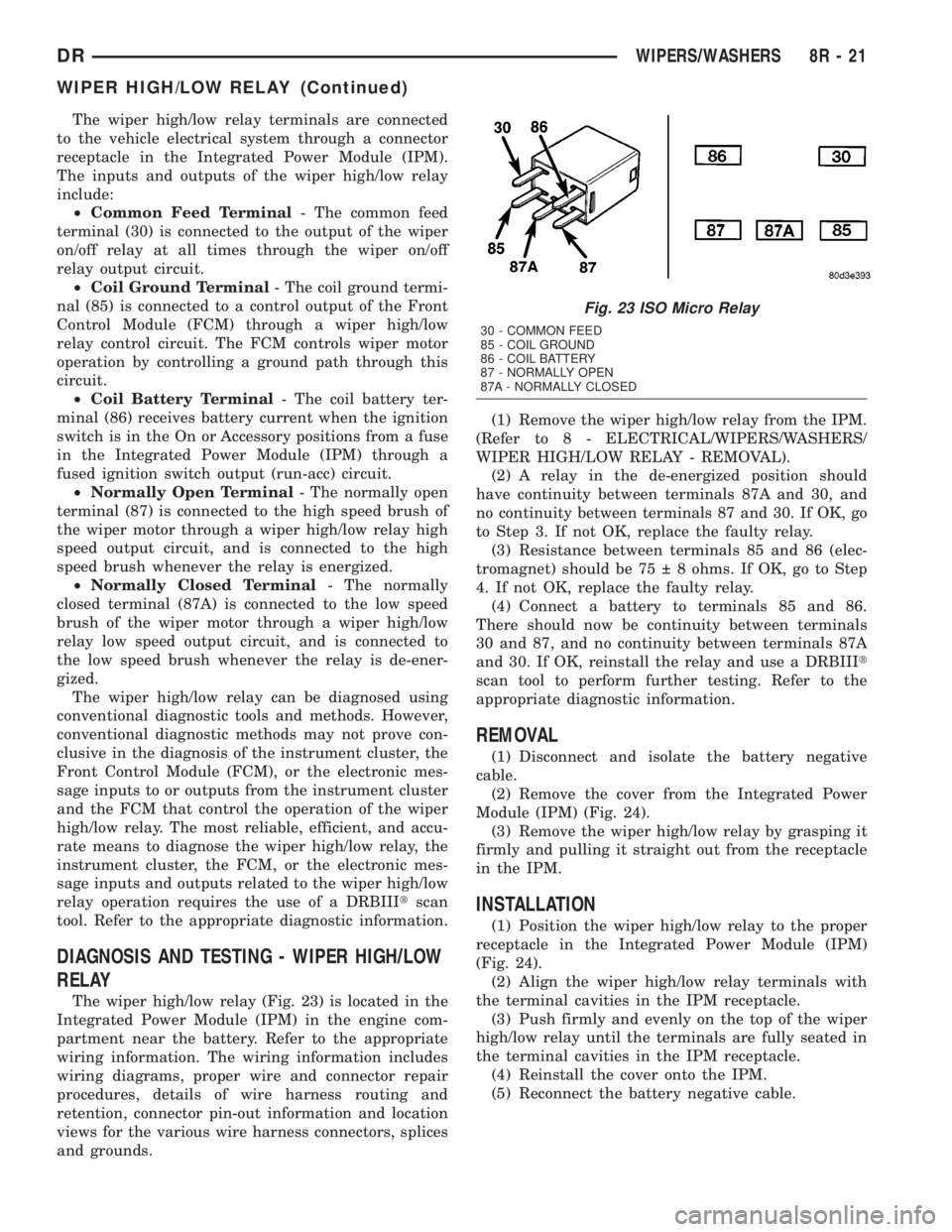
The wiper high/low relay terminals are connected
to the vehicle electrical system through a connector
receptacle in the Integrated Power Module (IPM).
The inputs and outputs of the wiper high/low relay
include:
²Common Feed Terminal- The common feed
terminal (30) is connected to the output of the wiper
on/off relay at all times through the wiper on/off
relay output circuit.
²Coil Ground Terminal- The coil ground termi-
nal (85) is connected to a control output of the Front
Control Module (FCM) through a wiper high/low
relay control circuit. The FCM controls wiper motor
operation by controlling a ground path through this
circuit.
²Coil Battery Terminal- The coil battery ter-
minal (86) receives battery current when the ignition
switch is in the On or Accessory positions from a fuse
in the Integrated Power Module (IPM) through a
fused ignition switch output (run-acc) circuit.
²Normally Open Terminal- The normally open
terminal (87) is connected to the high speed brush of
the wiper motor through a wiper high/low relay high
speed output circuit, and is connected to the high
speed brush whenever the relay is energized.
²Normally Closed Terminal- The normally
closed terminal (87A) is connected to the low speed
brush of the wiper motor through a wiper high/low
relay low speed output circuit, and is connected to
the low speed brush whenever the relay is de-ener-
gized.
The wiper high/low relay can be diagnosed using
conventional diagnostic tools and methods. However,
conventional diagnostic methods may not prove con-
clusive in the diagnosis of the instrument cluster, the
Front Control Module (FCM), or the electronic mes-
sage inputs to or outputs from the instrument cluster
and the FCM that control the operation of the wiper
high/low relay. The most reliable, efficient, and accu-
rate means to diagnose the wiper high/low relay, the
instrument cluster, the FCM, or the electronic mes-
sage inputs and outputs related to the wiper high/low
relay operation requires the use of a DRBIIItscan
tool. Refer to the appropriate diagnostic information.
DIAGNOSIS AND TESTING - WIPER HIGH/LOW
RELAY
The wiper high/low relay (Fig. 23) is located in the
Integrated Power Module (IPM) in the engine com-
partment near the battery. Refer to the appropriate
wiring information. The wiring information includes
wiring diagrams, proper wire and connector repair
procedures, details of wire harness routing and
retention, connector pin-out information and location
views for the various wire harness connectors, splices
and grounds.(1) Remove the wiper high/low relay from the IPM.
(Refer to 8 - ELECTRICAL/WIPERS/WASHERS/
WIPER HIGH/LOW RELAY - REMOVAL).
(2) A relay in the de-energized position should
have continuity between terminals 87A and 30, and
no continuity between terminals 87 and 30. If OK, go
to Step 3. If not OK, replace the faulty relay.
(3) Resistance between terminals 85 and 86 (elec-
tromagnet) should be 75 8 ohms. If OK, go to Step
4. If not OK, replace the faulty relay.
(4) Connect a battery to terminals 85 and 86.
There should now be continuity between terminals
30 and 87, and no continuity between terminals 87A
and 30. If OK, reinstall the relay and use a DRBIIIt
scan tool to perform further testing. Refer to the
appropriate diagnostic information.
REMOVAL
(1) Disconnect and isolate the battery negative
cable.
(2) Remove the cover from the Integrated Power
Module (IPM) (Fig. 24).
(3) Remove the wiper high/low relay by grasping it
firmly and pulling it straight out from the receptacle
in the IPM.
INSTALLATION
(1) Position the wiper high/low relay to the proper
receptacle in the Integrated Power Module (IPM)
(Fig. 24).
(2) Align the wiper high/low relay terminals with
the terminal cavities in the IPM receptacle.
(3) Push firmly and evenly on the top of the wiper
high/low relay until the terminals are fully seated in
the terminal cavities in the IPM receptacle.
(4) Reinstall the cover onto the IPM.
(5) Reconnect the battery negative cable.
Fig. 23 ISO Micro Relay
30 - COMMON FEED
85 - COIL GROUND
86 - COIL BATTERY
87 - NORMALLY OPEN
87A - NORMALLY CLOSED
DRWIPERS/WASHERS 8R - 21
WIPER HIGH/LOW RELAY (Continued)
Page 701 of 2895
DIAGNOSIS AND TESTING - WIPER ON/OFF
RELAY
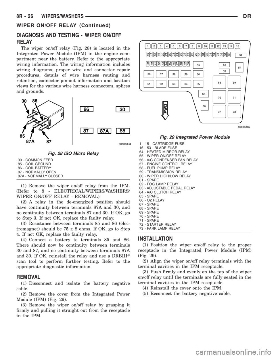
The wiper on/off relay (Fig. 28) is located in the
Integrated Power Module (IPM) in the engine com-
partment near the battery. Refer to the appropriate
wiring information. The wiring information includes
wiring diagrams, proper wire and connector repair
procedures, details of wire harness routing and
retention, connector pin-out information and location
views for the various wire harness connectors, splices
and grounds.
(1) Remove the wiper on/off relay from the IPM.
(Refer to 8 - ELECTRICAL/WIPERS/WASHERS/
WIPER ON/OFF RELAY - REMOVAL).
(2) A relay in the de-energized position should
have continuity between terminals 87A and 30, and
no continuity between terminals 87 and 30. If OK, go
to Step 3. If not OK, replace the faulty relay.
(3) Resistance between terminals 85 and 86 (elec-
tromagnet) should be 75 8 ohms. If OK, go to Step
4. If not OK, replace the faulty relay.
(4) Connect a battery to terminals 85 and 86.
There should now be continuity between terminals
30 and 87, and no continuity between terminals 87A
and 30. If OK, reinstall the relay and use a DRBIIIt
scan tool to perform further testing. Refer to the
appropriate diagnostic information.
REMOVAL
(1) Disconnect and isolate the battery negative
cable.
(2) Remove the cover from the Integrated Power
Module (IPM) (Fig. 29).
(3) Remove the wiper on/off relay by grasping it
firmly and pulling it straight out from the receptacle
in the IPM.
INSTALLATION
(1) Position the wiper on/off relay to the proper
receptacle in the Integrated Power Module (IPM)
(Fig. 29).
(2) Align the wiper on/off relay terminals with the
terminal cavities in the IPM receptacle.
(3) Push firmly and evenly on the top of the wiper
on/off relay until the terminals are fully seated in the
terminal cavities in the IPM receptacle.
(4) Reinstall the cover onto the IPM.
(5) Reconnect the battery negative cable.
Fig. 28 ISO Micro Relay
30 - COMMON FEED
85 - COIL GROUND
86 - COIL BATTERY
87 - NORMALLY OPEN
87A - NORMALLY CLOSED
Fig. 29 Integrated Power Module
1 - 15 - CARTRIDGE FUSE
16 - 53 - BLADE FUSE
54 - HEATED MIRROR RELAY
55 - WIPER ON/OFF RELAY
56 - A/C CONDENSER FAN RELAY
57 - ENGINE CONTROL RELAY
58 - FUEL PUMP RELAY
59 - TRANSMISSION RELAY
60 - WIPER HIGH/LOW RELAY
61 - SPARE
62 - FOG LAMP RELAY
63 - ADJUSTABLE PEDAL RELAY
64 - A/C CLUTCH RELAY
65 - SPARE
66 - O2 RELAY
67 - SPARE
68 - SPARE
69 - SPARE
70 - SPARE
71 - SPARE
72 - STARTER RELAY
73 - PARK LAMP RELAY
8R - 26 WIPERS/WASHERSDR
WIPER ON/OFF RELAY (Continued)
Page 704 of 2895

8W-01 WIRING DIAGRAM INFORMATION
TABLE OF CONTENTS
page page
WIRING DIAGRAM INFORMATION
DESCRIPTION
DESCRIPTION - HOW TO USE WIRING
DIAGRAMS...........................1
DESCRIPTION - CIRCUIT INFORMATION....5
DESCRIPTION - CIRCUIT FUNCTIONS......6
DESCRIPTION - SECTION IDENTIFICATION
AND INFORMATION....................6
DESCRIPTION - CONNECTOR, GROUND
AND SPLICE INFORMATION..............7
WARNING
WARNINGS - GENERAL.................7
DIAGNOSIS AND TESTING - WIRING
HARNESS............................7
STANDARD PROCEDURE
STANDARD PROCEDURE -
ELECTROSTATIC DISCHARGE (ESD)
SENSITIVE DEVICES...................8
STANDARD PROCEDURE - TESTING OF
VOLTAGE POTENTIAL...................9
STANDARD PROCEDURE - TESTING FOR
CONTINUITY..........................9STANDARD PROCEDURE - TESTING FOR A
SHORT TO GROUND...................9
STANDARD PROCEDURE - TESTING FOR A
SHORT TO GROUND ON FUSES
POWERING SEVERAL LOADS...........10
STANDARD PROCEDURE - TESTING FOR A
VOLTAGE DROP......................10
SPECIAL TOOLS
WIRING/TERMINAL....................10
CONNECTOR
REMOVAL.............................11
INSTALLATION.........................11
DIODE
REMOVAL.............................14
INSTALLATION.........................14
TERMINAL
REMOVAL.............................14
INSTALLATION.........................14
WIRE
STANDARD PROCEDURE - WIRE SPLICING . . 15
WIRING DIAGRAM
INFORMATION
DESCRIPTION
DESCRIPTION - HOW TO USE WIRING
DIAGRAMS
DaimlerChrysler Corporation wiring diagrams are
designed to provide information regarding the vehi-
cles wiring content. In order to effectively use the
wiring diagrams to diagnose and repair
DaimlerChrysler Corporation vehicles, it is important
to understand all of their features and characteris-
tics.
Diagrams are arranged such that the power (B+)
side of the circuit is placed near the top of the page,
and the ground (B-) side of the circuit is placed near
the bottom of the page (Fig. 1).
All switches, components, and modules are shown
in the at rest position with the doors closed and the
key removed from the ignition (Fig. 2).Components are shown two ways. A solid line
around a component indicates that the component is
complete. A dashed line around the component indi-
cates that the component is being shown is not com-
plete. Incomplete components have a reference
number to indicate the page where the component is
shown complete.
It is important to realize that no attempt is made
on the diagrams to represent components and wiring
as they appear on the vehicle. For example, a short
piece of wire is treated the same as a long one. In
addition, switches and other components are shown
as simply as possible, with regard to function only.
SYMBOLS
International symbols are used throughout the wir-
ing diagrams. These symbols are consistent with
those being used around the world (Fig. 3).
DR8W-01 WIRING DIAGRAM INFORMATION 8W - 01 - 1