2003 DODGE RAM light
[x] Cancel search: lightPage 1959 of 2895
(14) Use Installer to install the reverse counter-
shaft bearing race into the extension/adapter hous-
ing.
(15) Install back-up lamp switch into the exten-
sion/adapter housing and tighten to 28 N´m (20
ft.lbs.).
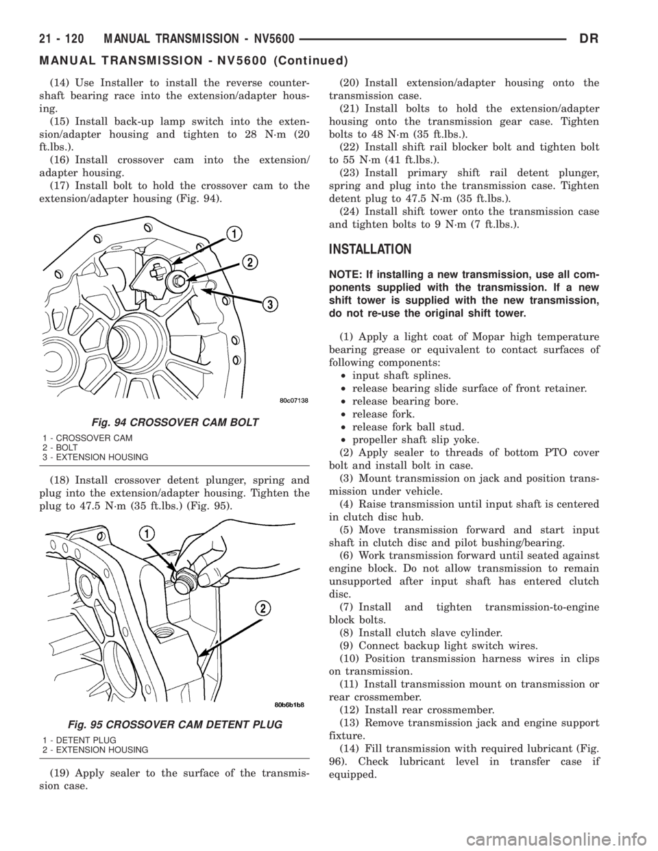
(16) Install crossover cam into the extension/
adapter housing.
(17) Install bolt to hold the crossover cam to the
extension/adapter housing (Fig. 94).
(18) Install crossover detent plunger, spring and
plug into the extension/adapter housing. Tighten the
plug to 47.5 N´m (35 ft.lbs.) (Fig. 95).
(19) Apply sealer to the surface of the transmis-
sion case.(20) Install extension/adapter housing onto the
transmission case.
(21) Install bolts to hold the extension/adapter
housing onto the transmission gear case. Tighten
bolts to 48 N´m (35 ft.lbs.).
(22) Install shift rail blocker bolt and tighten bolt
to 55 N´m (41 ft.lbs.).
(23) Install primary shift rail detent plunger,
spring and plug into the transmission case. Tighten
detent plug to 47.5 N´m (35 ft.lbs.).
(24) Install shift tower onto the transmission case
and tighten bolts to 9 N´m (7 ft.lbs.).
INSTALLATION
NOTE: If installing a new transmission, use all com-
ponents supplied with the transmission. If a new
shift tower is supplied with the new transmission,
do not re-use the original shift tower.
(1) Apply a light coat of Mopar high temperature
bearing grease or equivalent to contact surfaces of
following components:
²input shaft splines.
²release bearing slide surface of front retainer.
²release bearing bore.
²release fork.
²release fork ball stud.
²propeller shaft slip yoke.
(2) Apply sealer to threads of bottom PTO cover
bolt and install bolt in case.
(3) Mount transmission on jack and position trans-
mission under vehicle.
(4) Raise transmission until input shaft is centered
in clutch disc hub.
(5) Move transmission forward and start input
shaft in clutch disc and pilot bushing/bearing.
(6) Work transmission forward until seated against
engine block. Do not allow transmission to remain
unsupported after input shaft has entered clutch
disc.
(7) Install and tighten transmission-to-engine
block bolts.
(8) Install clutch slave cylinder.
(9) Connect backup light switch wires.
(10) Position transmission harness wires in clips
on transmission.
(11) Install transmission mount on transmission or
rear crossmember.
(12) Install rear crossmember.
(13) Remove transmission jack and engine support
fixture.
(14) Fill transmission with required lubricant (Fig.
96). Check lubricant level in transfer case if
equipped.
Fig. 94 CROSSOVER CAM BOLT
1 - CROSSOVER CAM
2 - BOLT
3 - EXTENSION HOUSING
Fig. 95 CROSSOVER CAM DETENT PLUG
1 - DETENT PLUG
2 - EXTENSION HOUSING
21 - 120 MANUAL TRANSMISSION - NV5600DR
MANUAL TRANSMISSION - NV5600 (Continued)
Page 1996 of 2895
(10) Rotate crankshaft in clockwise direction until
converter bolts are accessible. Then remove bolts one
at a time. Rotate crankshaft with socket wrench on
dampener bolt.
(11) Mark propeller shaft and axle yokes for
assembly alignment. Then disconnect and remove
propeller shaft. On4x4models, remove both propel-
ler shafts. (Refer to 3 - DIFFERENTIAL & DRIV-
ELINE/PROPELLER SHAFT/PROPELLER SHAFT -
REMOVAL)
(12) Disconnect wires from the transmission range
sensor and transmission solenoid connector.
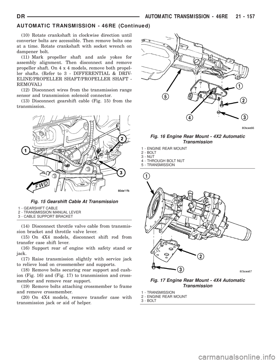
(13) Disconnect gearshift cable (Fig. 15) from the
transmission.
(14) Disconnect throttle valve cable from transmis-
sion bracket and throttle valve lever.
(15) On 4X4 models, disconnect shift rod from
transfer case shift lever.
(16) Support rear of engine with safety stand or
jack.
(17) Raise transmission slightly with service jack
to relieve load on crossmember and supports.
(18) Remove bolts securing rear support and cush-
ion (Fig. 16) and (Fig. 17) to transmission and cross-
member and remove rear support.
(19) Remove bolts attaching crossmember to frame
and remove crossmember.
(20) On 4X4 models, remove transfer case with
transmission jack or aid of helper.
Fig. 15 Gearshift Cable At Transmission
1 - GEARSHIFT CABLE
2 - TRANSMISSION MANUAL LEVER
3 - CABLE SUPPORT BRACKET
Fig. 16 Engine Rear Mount - 4X2 Automatic
Transmission
1 - ENGINE REAR MOUNT
2 - BOLT
3 - NUT
4 - THROUGH BOLT NUT
5 - TRANSMISSION
Fig. 17 Engine Rear Mount - 4X4 Automatic
Transmission
1 - TRANSMISSION
2 - ENGINE REAR MOUNT
3 - BOLT
DRAUTOMATIC TRANSMISSION - 46RE 21 - 157
AUTOMATIC TRANSMISSION - 46RE (Continued)
Page 2000 of 2895
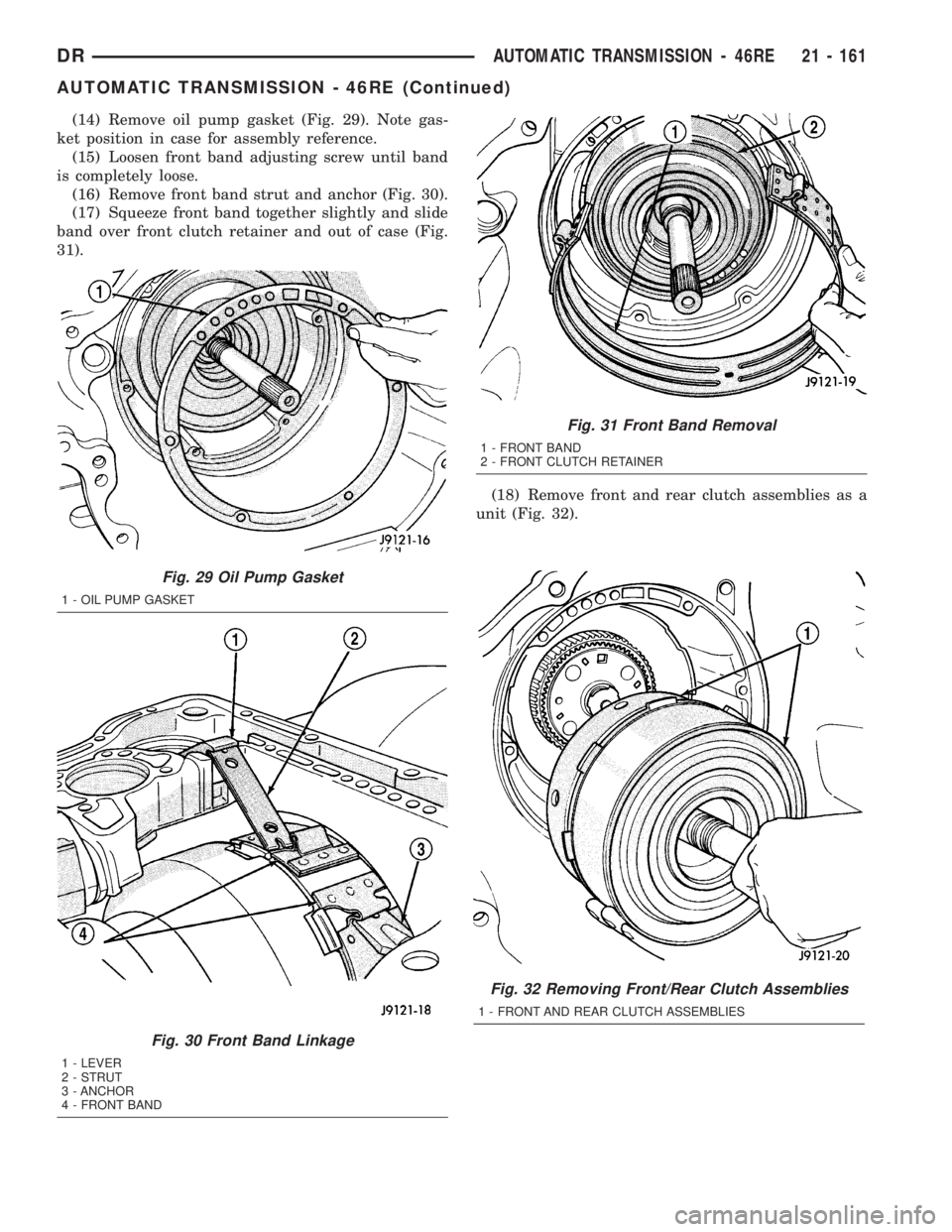
(14) Remove oil pump gasket (Fig. 29). Note gas-
ket position in case for assembly reference.
(15) Loosen front band adjusting screw until band
is completely loose.
(16) Remove front band strut and anchor (Fig. 30).
(17) Squeeze front band together slightly and slide
band over front clutch retainer and out of case (Fig.
31).
(18) Remove front and rear clutch assemblies as a
unit (Fig. 32).
Fig. 32 Removing Front/Rear Clutch Assemblies
1 - FRONT AND REAR CLUTCH ASSEMBLIES
Fig. 29 Oil Pump Gasket
1 - OIL PUMP GASKET
Fig. 30 Front Band Linkage
1 - LEVER
2 - STRUT
3 - ANCHOR
4 - FRONT BAND
Fig. 31 Front Band Removal
1 - FRONT BAND
2 - FRONT CLUTCH RETAINER
DRAUTOMATIC TRANSMISSION - 46RE 21 - 161
AUTOMATIC TRANSMISSION - 46RE (Continued)
Page 2005 of 2895
FRONT/REAR SERVO
(1) Lubricate rear servo piston seal with Mopart
Door Ease or ATF +4. Lubricate servo bore in case
with ATF +4.
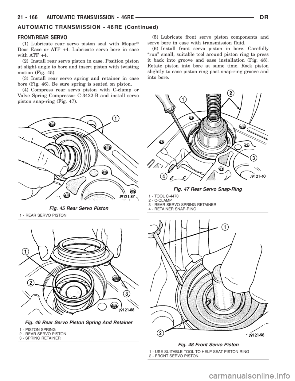
(2) Install rear servo piston in case. Position piston
at slight angle to bore and insert piston with twisting
motion (Fig. 45).
(3) Install rear servo spring and retainer in case
bore (Fig. 46). Be sure spring is seated on piston.
(4) Compress rear servo piston with C-clamp or
Valve Spring Compressor C-3422-B and install servo
piston snap-ring (Fig. 47).(5) Lubricate front servo piston components and
servo bore in case with transmission fluid.
(6) Install front servo piston in bore. Carefully
ªrunº small, suitable tool around piston ring to press
it back into groove and ease installation (Fig. 48).
Rotate piston into bore at same time. Rock piston
slightly to ease piston ring past snap-ring groove and
into bore.
Fig. 45 Rear Servo Piston
1 - REAR SERVO PISTON
Fig. 46 Rear Servo Piston Spring And Retainer
1 - PISTON SPRING
2 - REAR SERVO PISTON
3 - SPRING RETAINER
Fig. 47 Rear Servo Snap-Ring
1 - TOOL C-4470
2 - C-CLAMP
3 - REAR SERVO SPRING RETAINER
4 - RETAINER SNAP-RING
Fig. 48 Front Servo Piston
1 - USE SUITABLE TOOL TO HELP SEAT PISTON RING
2 - FRONT SERVO PISTON
21 - 166 AUTOMATIC TRANSMISSION - 46REDR
AUTOMATIC TRANSMISSION - 46RE (Continued)
Page 2012 of 2895
CAUTION: If the condition of the transmission
before the overhaul procedure caused excessive
metallic or fiber contamination in the fluid, replace
the torque converter. Fluid contamination and trans-
mission failure can result if not done.
(6) Install torque converter. Use C-clamp or metal
strap to hold converter in place for installation.
BAND ADJUSTMENT AND FINAL
(1) Adjust front and rear bands as follows:
(a) Loosen locknut on each band adjusting screw
4-5 turns.
(b) Tighten both adjusting screws to 8 N´m (72
in. lbs.).
(c) Back off front band adjusting screw 2-7/8
turns.
(d) Back off rear band adjusting screw 2 turns.
(e) Hold each adjusting screw in position and
tighten locknut to 34 N´m (25 ft. lbs.) torque.
(2) Install magnet in oil pan. Magnet seats on
small protrusion at corner of pan.
(3) Position new oil pan gasket on case and install
oil pan. Tighten pan bolts to 17 N´m (13 ft. lbs.).
(4) Install throttle valve and shift selector levers
on valve body manual lever shaft.
(5) Apply small quantity of dielectric grease to ter-
minal pins of solenoid case connector and transmis-
sion range sensor.
(6) Fill transmission with recommended fluid.
Refer to Service Procedures section of this group.
INSTALLATION
(1) Check torque converter hub and hub drive
notches for sharp edges burrs, scratches, or nicks.
Polish the hub and notches with 320/400 grit paper
and crocus cloth if necessary. The hub must be
smooth to avoid damaging pump seal at installation.
(2) Lubricate pocket in the rear oil pump seal lip
with transmission fluid.
(3) Lubricate converter pilot hub of the crankshaft
with a light coating of MopartHigh Temp Grease.
(4) Align and install converter in oil pump.
(5) Carefully insert converter in oil pump. Then
rotate converter back and forth until fully seated in
pump gears.
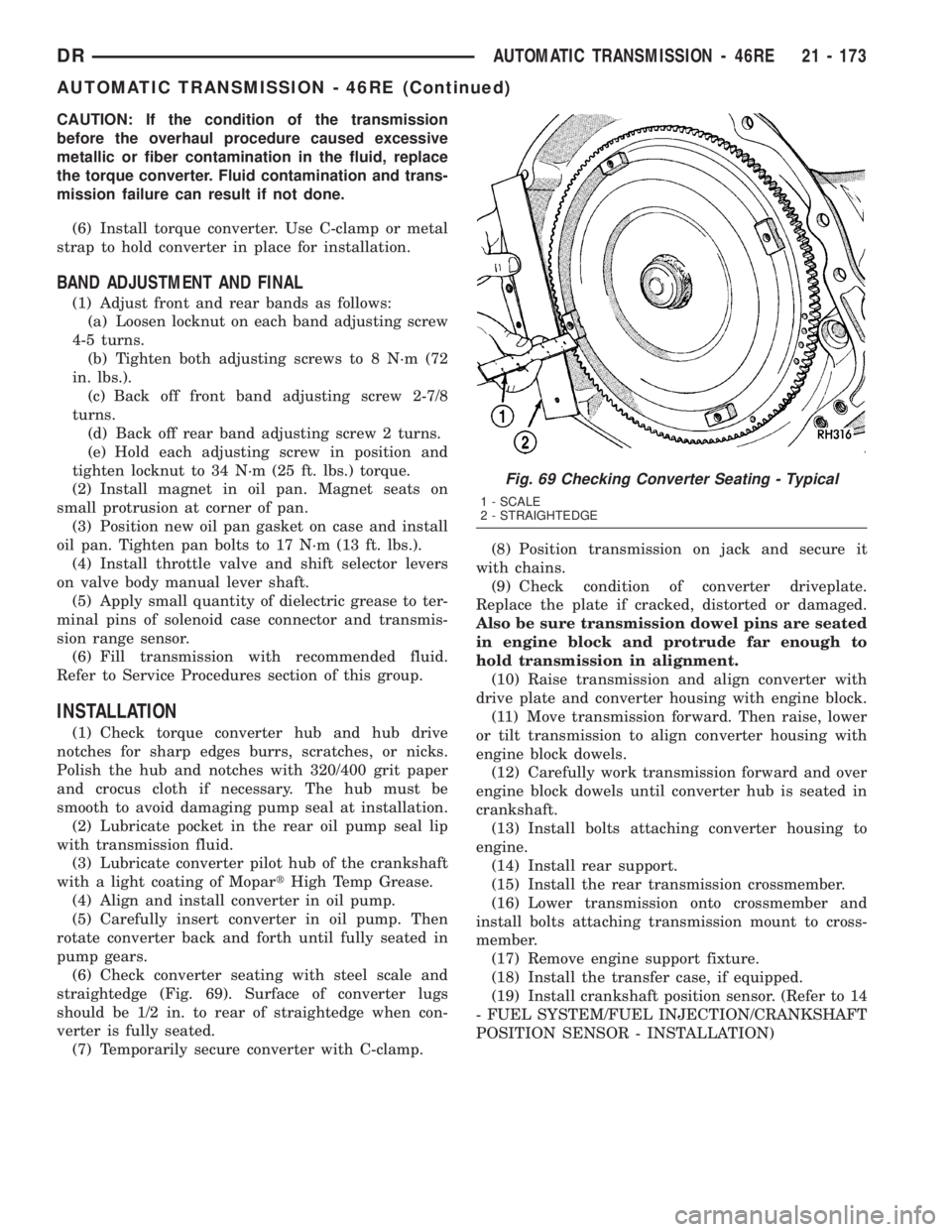
(6) Check converter seating with steel scale and
straightedge (Fig. 69). Surface of converter lugs
should be 1/2 in. to rear of straightedge when con-
verter is fully seated.
(7) Temporarily secure converter with C-clamp.(8) Position transmission on jack and secure it
with chains.
(9) Check condition of converter driveplate.
Replace the plate if cracked, distorted or damaged.
Also be sure transmission dowel pins are seated
in engine block and protrude far enough to
hold transmission in alignment.
(10) Raise transmission and align converter with
drive plate and converter housing with engine block.
(11) Move transmission forward. Then raise, lower
or tilt transmission to align converter housing with
engine block dowels.
(12) Carefully work transmission forward and over
engine block dowels until converter hub is seated in
crankshaft.
(13) Install bolts attaching converter housing to
engine.
(14) Install rear support.
(15) Install the rear transmission crossmember.
(16) Lower transmission onto crossmember and
install bolts attaching transmission mount to cross-
member.
(17) Remove engine support fixture.
(18) Install the transfer case, if equipped.
(19) Install crankshaft position sensor. (Refer to 14
- FUEL SYSTEM/FUEL INJECTION/CRANKSHAFT
POSITION SENSOR - INSTALLATION)
Fig. 69 Checking Converter Seating - Typical
1 - SCALE
2 - STRAIGHTEDGE
DRAUTOMATIC TRANSMISSION - 46RE 21 - 173
AUTOMATIC TRANSMISSION - 46RE (Continued)
Page 2057 of 2895
OVERDRIVE CLUTCH
DESCRIPTION
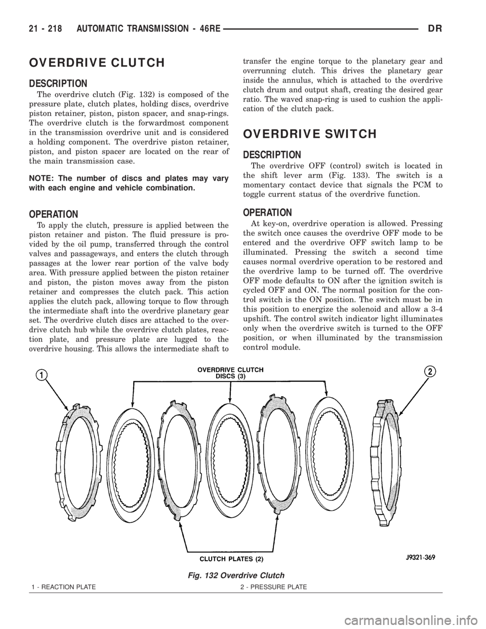
The overdrive clutch (Fig. 132) is composed of the
pressure plate, clutch plates, holding discs, overdrive
piston retainer, piston, piston spacer, and snap-rings.
The overdrive clutch is the forwardmost component
in the transmission overdrive unit and is considered
a holding component. The overdrive piston retainer,
piston, and piston spacer are located on the rear of
the main transmission case.
NOTE: The number of discs and plates may vary
with each engine and vehicle combination.
OPERATION
To apply the clutch, pressure is applied between the
piston retainer and piston. The fluid pressure is pro-
vided by the oil pump, transferred through the control
valves and passageways, and enters the clutch through
passages at the lower rear portion of the valve body
area. With pressure applied between the piston retainer
and piston, the piston moves away from the piston
retainer and compresses the clutch pack. This action
applies the clutch pack, allowing torque to flow through
the intermediate shaft into the overdrive planetary gear
set. The overdrive clutch discs are attached to the over-
drive clutch hub while the overdrive clutch plates, reac-
tion plate, and pressure plate are lugged to the
overdrive housing. This allows the intermediate shaft totransfer the engine torque to the planetary gear and
overrunning clutch. This drives the planetary gear
inside the annulus, which is attached to the overdrive
clutch drum and output shaft, creating the desired gear
ratio. The waved snap-ring is used to cushion the appli-
cation of the clutch pack.
OVERDRIVE SWITCH
DESCRIPTION
The overdrive OFF (control) switch is located in
the shift lever arm (Fig. 133). The switch is a
momentary contact device that signals the PCM to
toggle current status of the overdrive function.
OPERATION
At key-on, overdrive operation is allowed. Pressing
the switch once causes the overdrive OFF mode to be
entered and the overdrive OFF switch lamp to be
illuminated. Pressing the switch a second time
causes normal overdrive operation to be restored and
the overdrive lamp to be turned off. The overdrive
OFF mode defaults to ON after the ignition switch is
cycled OFF and ON. The normal position for the con-
trol switch is the ON position. The switch must be in
this position to energize the solenoid and allow a 3-4
upshift. The control switch indicator light illuminates
only when the overdrive switch is turned to the OFF
position, or when illuminated by the transmission
control module.
Fig. 132 Overdrive Clutch
1 - REACTION PLATE 2 - PRESSURE PLATE
21 - 218 AUTOMATIC TRANSMISSION - 46REDR
Page 2070 of 2895
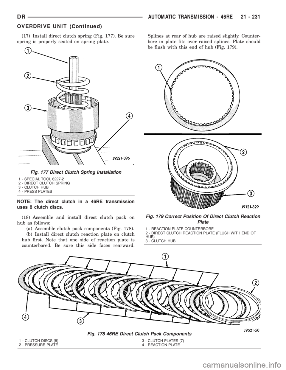
(17) Install direct clutch spring (Fig. 177). Be sure
spring is properly seated on spring plate.
NOTE: The direct clutch in a 46RE transmission
uses 8 clutch discs.
(18) Assemble and install direct clutch pack on
hub as follows:
(a) Assemble clutch pack components (Fig. 178).
(b) Install direct clutch reaction plate on clutch
hub first. Note that one side of reaction plate is
counterbored. Be sure this side faces rearward.Splines at rear of hub are raised slightly. Counter-
bore in plate fits over raised splines. Plate should
be flush with this end of hub (Fig. 179).
Fig. 178 46RE Direct Clutch Pack Components
1 - CLUTCH DISCS (8) 3 - CLUTCH PLATES (7)
2 - PRESSURE PLATE 4 - REACTION PLATE
Fig. 179 Correct Position Of Direct Clutch Reaction
Plate
1 - REACTION PLATE COUNTERBORE
2 - DIRECT CLUTCH REACTION PLATE (FLUSH WITH END OF
HUB)
3 - CLUTCH HUB
Fig. 177 Direct Clutch Spring Installation
1 - SPECIAL TOOL 6227-2
2 - DIRECT CLUTCH SPRING
3 - CLUTCH HUB
4 - PRESS PLATES
DRAUTOMATIC TRANSMISSION - 46RE 21 - 231
OVERDRIVE UNIT (Continued)
Page 2088 of 2895
OPERATION
To apply the clutch, pressure is applied between
the clutch retainer and piston. The fluid pressure is
provided by the oil pump, transferred through the
control valves and passageways, and enters the
clutch through the hub of the reaction shaft support.
With pressure applied between the clutch retainer
and piston, the piston moves away from the clutch
retainer and compresses the clutch pack. This action
applies the clutch pack, allowing torque to flow
through the input shaft into the driving discs, and
into the clutch plates and pressure plate that are
lugged to the clutch retainer. The waved spring is
used to cushion the application of the clutch pack.
The snap-ring is selective and used to adjust clutch
pack clearance.
When pressure is released from the piston, the
spring returns the piston to its fully released position
and disengages the clutch. The release spring also
helps to cushion the application of the clutch assem-
bly. When the clutch is in the process of being
released by the release spring, fluid flows through a
vent and one-way ball-check-valve located in the pis-ton. The check-valve is needed to eliminate the pos-
sibility of plate drag caused by centrifugal force
acting on the residual fluid trapped in the clutch pis-
ton retainer.
DISASSEMBLY
(1) Remove fiber thrust washer from forward side
of clutch retainer.
(2) Remove input shaft front and rear seal rings.
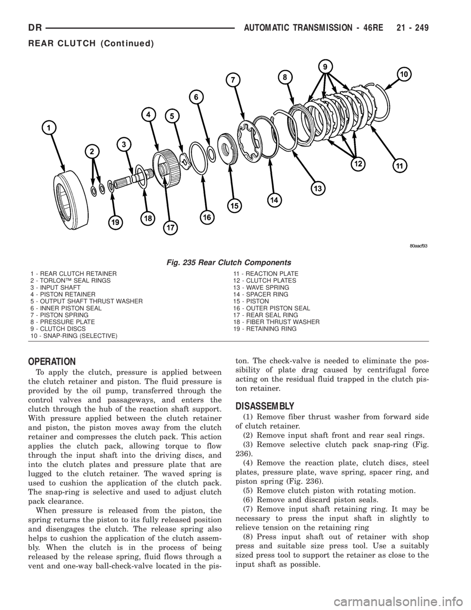
(3) Remove selective clutch pack snap-ring (Fig.
236).
(4) Remove the reaction plate, clutch discs, steel
plates, pressure plate, wave spring, spacer ring, and
piston spring (Fig. 236).
(5) Remove clutch piston with rotating motion.
(6) Remove and discard piston seals.
(7) Remove input shaft retaining ring. It may be
necessary to press the input shaft in slightly to
relieve tension on the retaining ring
(8) Press input shaft out of retainer with shop
press and suitable size press tool. Use a suitably
sized press tool to support the retainer as close to the
input shaft as possible.
Fig. 235 Rear Clutch Components
1 - REAR CLUTCH RETAINER 11 - REACTION PLATE
2 - TORLONŸ SEAL RINGS 12 - CLUTCH PLATES
3 - INPUT SHAFT 13 - WAVE SPRING
4 - PISTON RETAINER 14 - SPACER RING
5 - OUTPUT SHAFT THRUST WASHER 15 - PISTON
6 - INNER PISTON SEAL 16 - OUTER PISTON SEAL
7 - PISTON SPRING 17 - REAR SEAL RING
8 - PRESSURE PLATE 18 - FIBER THRUST WASHER
9 - CLUTCH DISCS 19 - RETAINING RING
10 - SNAP-RING (SELECTIVE)
DRAUTOMATIC TRANSMISSION - 46RE 21 - 249
REAR CLUTCH (Continued)