2003 DODGE RAM light
[x] Cancel search: lightPage 2186 of 2895
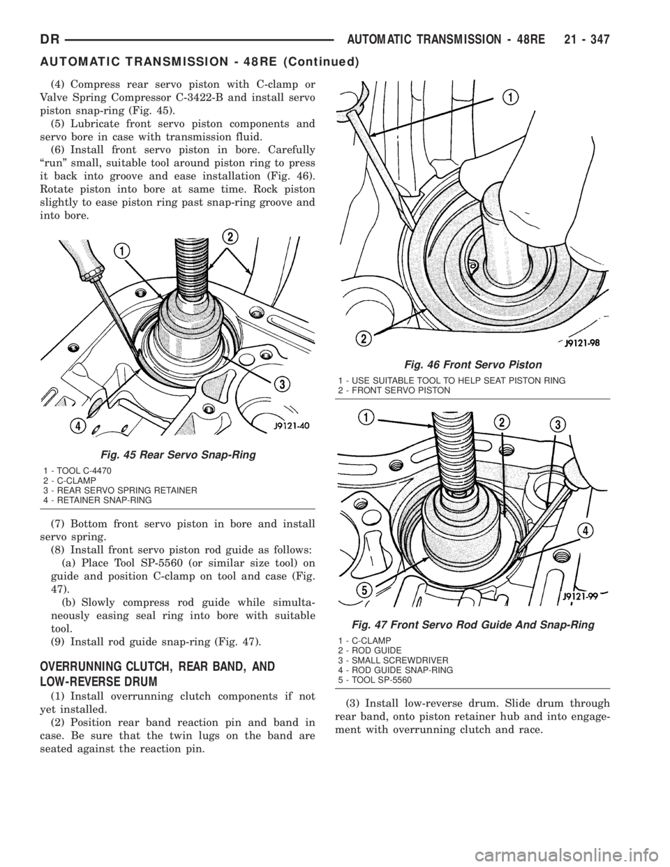
(4) Compress rear servo piston with C-clamp or
Valve Spring Compressor C-3422-B and install servo
piston snap-ring (Fig. 45).
(5) Lubricate front servo piston components and
servo bore in case with transmission fluid.
(6) Install front servo piston in bore. Carefully
ªrunº small, suitable tool around piston ring to press
it back into groove and ease installation (Fig. 46).
Rotate piston into bore at same time. Rock piston
slightly to ease piston ring past snap-ring groove and
into bore.
(7) Bottom front servo piston in bore and install
servo spring.
(8) Install front servo piston rod guide as follows:
(a) Place Tool SP-5560 (or similar size tool) on
guide and position C-clamp on tool and case (Fig.
47).
(b) Slowly compress rod guide while simulta-
neously easing seal ring into bore with suitable
tool.
(9) Install rod guide snap-ring (Fig. 47).
OVERRUNNING CLUTCH, REAR BAND, AND
LOW-REVERSE DRUM
(1) Install overrunning clutch components if not
yet installed.
(2) Position rear band reaction pin and band in
case. Be sure that the twin lugs on the band are
seated against the reaction pin.(3) Install low-reverse drum. Slide drum through
rear band, onto piston retainer hub and into engage-
ment with overrunning clutch and race.
Fig. 45 Rear Servo Snap-Ring
1 - TOOL C-4470
2 - C-CLAMP
3 - REAR SERVO SPRING RETAINER
4 - RETAINER SNAP-RING
Fig. 46 Front Servo Piston
1 - USE SUITABLE TOOL TO HELP SEAT PISTON RING
2 - FRONT SERVO PISTON
Fig. 47 Front Servo Rod Guide And Snap-Ring
1 - C-CLAMP
2 - ROD GUIDE
3 - SMALL SCREWDRIVER
4 - ROD GUIDE SNAP-RING
5 - TOOL SP-5560
DRAUTOMATIC TRANSMISSION - 48RE 21 - 347
AUTOMATIC TRANSMISSION - 48RE (Continued)
Page 2192 of 2895
(10) Install torque converter. Use C-clamp or metal
strap to hold converter in place for installation.
BAND ADJUSTMENT AND FINAL
(1) Adjust front and rear bands as follows:
(a) Loosen locknut on each band adjusting screw
4-5 turns.
(b) Tighten both adjusting screws to 8 N´m (72
in. lbs.).
(c) Back off front band adjusting screw 1-3/4
turns.
(d) Back off rear band adjusting screw 3 turns.
(e) Hold each adjusting screw in position and
tighten locknut to 34 N´m (25 ft. lbs.) torque.
(2) Install magnet in oil pan. Magnet seats on
small protrusion at corner of pan.
(3) Position new oil pan gasket on case and install
oil pan. Tighten pan bolts to 13.6 N´m (125 in. lbs.).
(4) Install throttle valve and shift selector levers
on valve body manual lever shaft.
(5) Apply small quantity of dielectric grease to ter-
minal pins of solenoid case connector and neutral
switch.
(6) Fill transmission with recommended fluid.
INSTALLATION
(1) Check torque converter hub inner and outer
diameters and hub drive notches for sharp edges
burrs, scratches, or nicks. Polish the hub and notches
with 320/400 grit paper and crocus cloth if necessary.
The hub must be smooth to avoid damaging pump
seal at installation.
(2) Lubricate pocket in the rear oil pump seal lip
with transmission fluid.
(3) Lubricate converter pilot hub of the crankshaft
with a light coating of MopartHigh Temp Grease.
(4) Align and install converter in oil pump.
(5) Carefully insert converter in oil pump. Then
rotate converter back and forth until fully seated in
pump gears.
(6) Check converter seating with steel scale and
straightedge (Fig. 65). Surface of converter lugs
should be 19mm (0.75 in.) to rear of straightedge
when converter is fully seated.
(7) Temporarily secure converter with C-clamp.
(8) Position transmission on jack and secure it
with chains.
(9) Check condition of converter driveplate.
Replace the plate if cracked, distorted or damaged.
Also be sure transmission dowel pins are seated
in engine block and protrude far enough to
hold transmission in alignment.
(10) Raise transmission and align converter with
drive plate and converter housing with engine block.
(11) Move transmission forward. Then raise, lower
or tilt transmission to align converter housing with
engine block dowels.
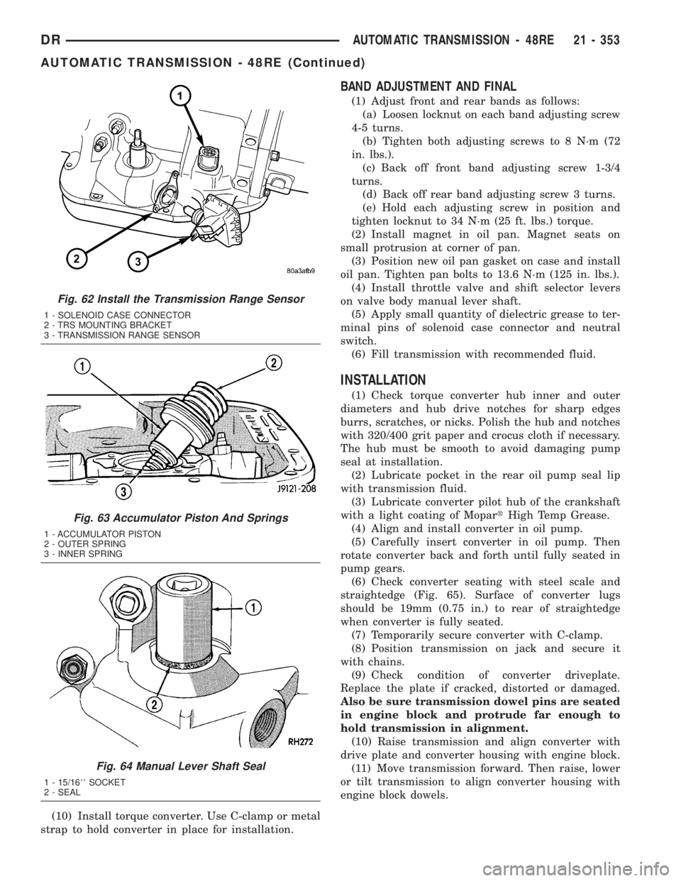
Fig. 62 Install the Transmission Range Sensor
1 - SOLENOID CASE CONNECTOR
2 - TRS MOUNTING BRACKET
3 - TRANSMISSION RANGE SENSOR
Fig. 63 Accumulator Piston And Springs
1 - ACCUMULATOR PISTON
2 - OUTER SPRING
3 - INNER SPRING
Fig. 64 Manual Lever Shaft Seal
1 - 15/1688SOCKET
2 - SEAL
DRAUTOMATIC TRANSMISSION - 48RE 21 - 353
AUTOMATIC TRANSMISSION - 48RE (Continued)
Page 2213 of 2895
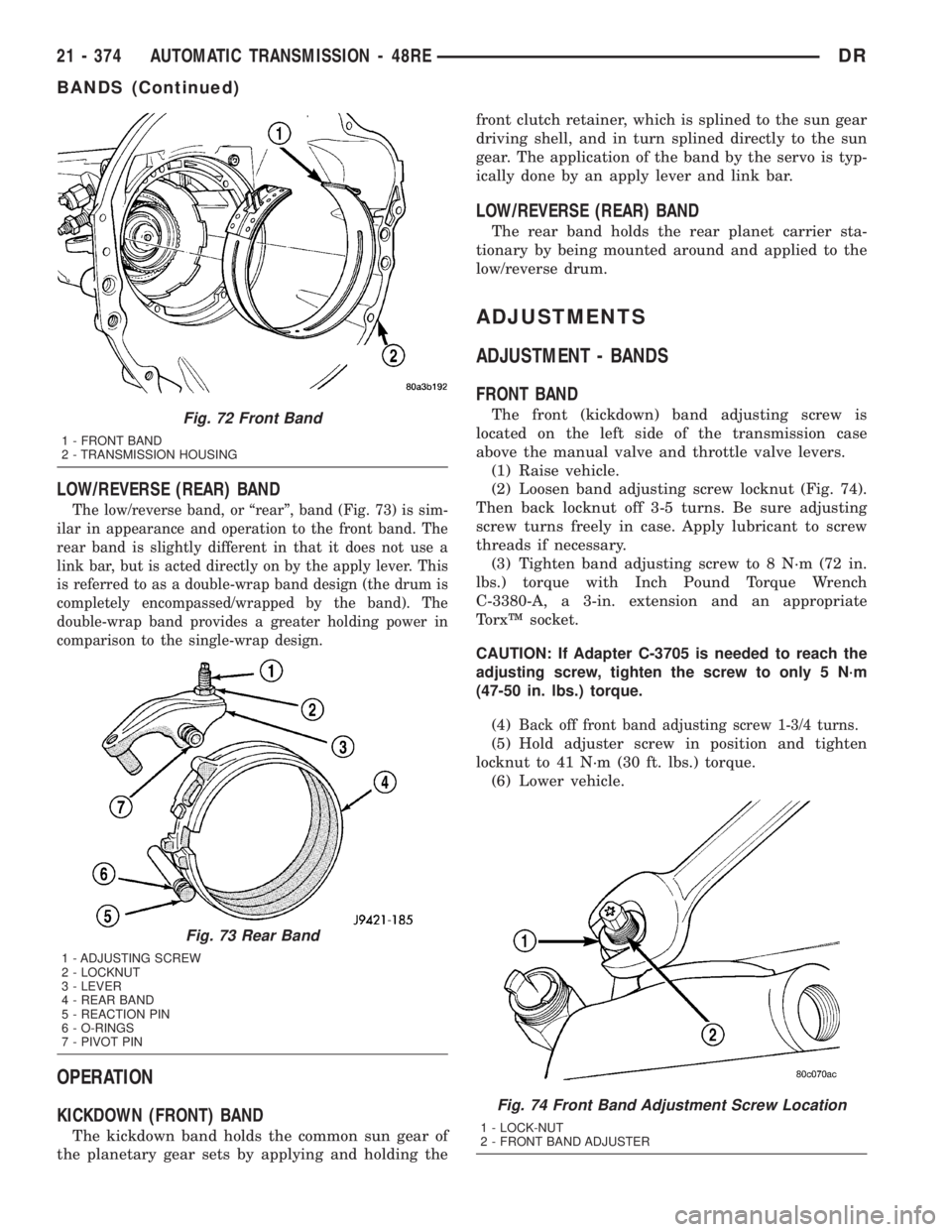
LOW/REVERSE (REAR) BAND
The low/reverse band, or ªrearº, band (Fig. 73) is sim-
ilar in appearance and operation to the front band. The
rear band is slightly different in that it does not use a
link bar, but is acted directly on by the apply lever. This
is referred to as a double-wrap band design (the drum is
completely encompassed/wrapped by the band). The
double-wrap band provides a greater holding power in
comparison to the single-wrap design.
OPERATION
KICKDOWN (FRONT) BAND
The kickdown band holds the common sun gear of
the planetary gear sets by applying and holding thefront clutch retainer, which is splined to the sun gear
driving shell, and in turn splined directly to the sun
gear. The application of the band by the servo is typ-
ically done by an apply lever and link bar.
LOW/REVERSE (REAR) BAND
The rear band holds the rear planet carrier sta-
tionary by being mounted around and applied to the
low/reverse drum.
ADJUSTMENTS
ADJUSTMENT - BANDS
FRONT BAND
The front (kickdown) band adjusting screw is
located on the left side of the transmission case
above the manual valve and throttle valve levers.
(1) Raise vehicle.
(2) Loosen band adjusting screw locknut (Fig. 74).
Then back locknut off 3-5 turns. Be sure adjusting
screw turns freely in case. Apply lubricant to screw
threads if necessary.
(3) Tighten band adjusting screw to 8 N´m (72 in.
lbs.) torque with Inch Pound Torque Wrench
C-3380-A, a 3-in. extension and an appropriate
TorxŸ socket.
CAUTION: If Adapter C-3705 is needed to reach the
adjusting screw, tighten the screw to only 5 N´m
(47-50 in. lbs.) torque.
(4)
Back off front band adjusting screw 1-3/4 turns.
(5) Hold adjuster screw in position and tighten
locknut to 41 N´m (30 ft. lbs.) torque.
(6) Lower vehicle.
Fig. 72 Front Band
1 - FRONT BAND
2 - TRANSMISSION HOUSING
Fig. 73 Rear Band
1 - ADJUSTING SCREW
2 - LOCKNUT
3 - LEVER
4 - REAR BAND
5 - REACTION PIN
6 - O-RINGS
7 - PIVOT PIN
Fig. 74 Front Band Adjustment Screw Location
1 - LOCK-NUT
2 - FRONT BAND ADJUSTER
21 - 374 AUTOMATIC TRANSMISSION - 48REDR
BANDS (Continued)
Page 2236 of 2895
OVERDRIVE SWITCH
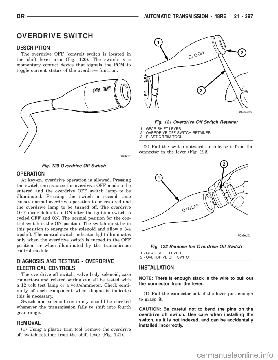
DESCRIPTION
The overdrive OFF (control) switch is located in
the shift lever arm (Fig. 120). The switch is a
momentary contact device that signals the PCM to
toggle current status of the overdrive function.
OPERATION
At key-on, overdrive operation is allowed. Pressing
the switch once causes the overdrive OFF mode to be
entered and the overdrive OFF switch lamp to be
illuminated. Pressing the switch a second time
causes normal overdrive operation to be restored and
the overdrive lamp to be turned off. The overdrive
OFF mode defaults to ON after the ignition switch is
cycled OFF and ON. The normal position for the con-
trol switch is the ON position. The switch must be in
this position to energize the solenoid and allow a 3-4
upshift. The control switch indicator light illuminates
only when the overdrive switch is turned to the OFF
position, or when illuminated by the transmission
control module.
DIAGNOSIS AND TESTING - OVERDRIVE
ELECTRICAL CONTROLS
The overdrive off switch, valve body solenoid, case
connectors and related wiring can all be tested with
a 12 volt test lamp or a volt/ohmmeter. Check conti-
nuity of each component when diagnosis indicates
this is necessary.
Switch and solenoid continuity should be checked
whenever the transmission fails to shift into fourth
gear range.
REMOVAL
(1) Using a plastic trim tool, remove the overdrive
off switch retainer from the shift lever (Fig. 121).(2) Pull the switch outwards to release it from the
connector in the lever (Fig. 122)
INSTALLATION
NOTE: There is enough slack in the wire to pull out
the connector from the lever.
(1) Pull the connector out of the lever just enough
to grasp it.
CAUTION: Be careful not to bend the pins on the
overdrive off switch. Use care when installing the
switch, as it is not indexed, and can be accidentally
installed incorrectly.
Fig. 120 Overdrive Off Switch
Fig. 121 Overdrive Off Switch Retainer
1 - GEAR SHIFT LEVER
2 - OVERDRIVE OFF SWITCH RETAINER
3 - PLASTIC TRIM TOOL
Fig. 122 Remove the Overdrive Off Switch
1 - GEAR SHIFT LEVER
2 - OVERDRIVE OFF SWITCH
DRAUTOMATIC TRANSMISSION - 48RE 21 - 397
Page 2248 of 2895
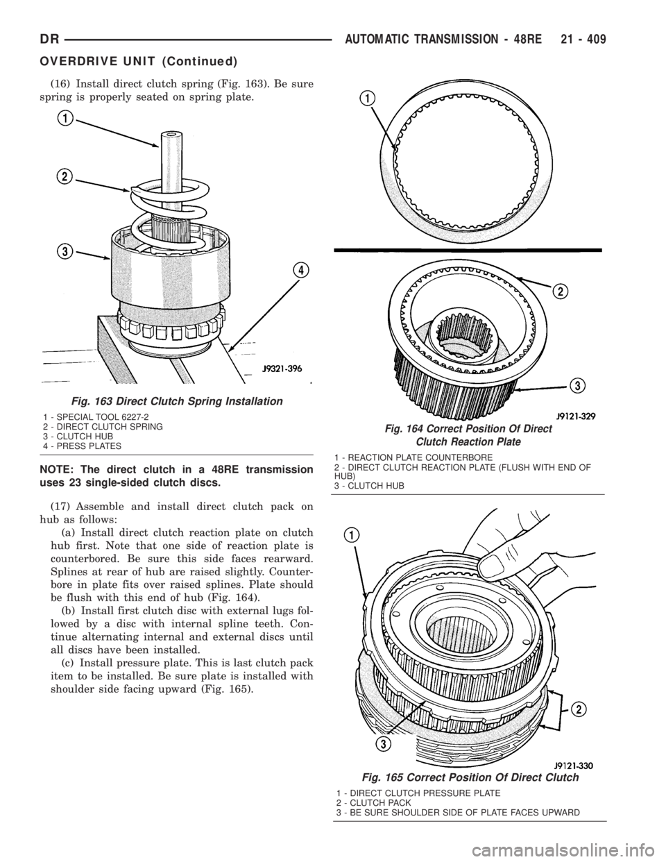
(16) Install direct clutch spring (Fig. 163). Be sure
spring is properly seated on spring plate.
NOTE: The direct clutch in a 48RE transmission
uses 23 single-sided clutch discs.
(17) Assemble and install direct clutch pack on
hub as follows:
(a) Install direct clutch reaction plate on clutch
hub first. Note that one side of reaction plate is
counterbored. Be sure this side faces rearward.
Splines at rear of hub are raised slightly. Counter-
bore in plate fits over raised splines. Plate should
be flush with this end of hub (Fig. 164).
(b) Install first clutch disc with external lugs fol-
lowed by a disc with internal spline teeth. Con-
tinue alternating internal and external discs until
all discs have been installed.
(c) Install pressure plate. This is last clutch pack
item to be installed. Be sure plate is installed with
shoulder side facing upward (Fig. 165).
Fig. 164 Correct Position Of Direct
Clutch Reaction Plate
1 - REACTION PLATE COUNTERBORE
2 - DIRECT CLUTCH REACTION PLATE (FLUSH WITH END OF
HUB)
3 - CLUTCH HUB
Fig. 165 Correct Position Of Direct Clutch
1 - DIRECT CLUTCH PRESSURE PLATE
2 - CLUTCH PACK
3 - BE SURE SHOULDER SIDE OF PLATE FACES UPWARD
Fig. 163 Direct Clutch Spring Installation
1 - SPECIAL TOOL 6227-2
2 - DIRECT CLUTCH SPRING
3 - CLUTCH HUB
4 - PRESS PLATES
DRAUTOMATIC TRANSMISSION - 48RE 21 - 409
OVERDRIVE UNIT (Continued)
Page 2266 of 2895
OPERATION
To apply the clutch, pressure is applied between
the clutch retainer and piston. The fluid pressure is
provided by the oil pump, transferred through the
control valves and passageways, and enters the
clutch through the hub of the reaction shaft support.
With pressure applied between the clutch retainer
and piston, the piston moves away from the clutch
retainer and compresses the clutch pack. This action
applies the clutch pack, allowing torque to flow
through the input shaft into the driving discs, and
into the clutch plates and pressure plate that are
lugged to the clutch retainer. The waved spring is
used to cushion the application of the clutch pack.
The snap-ring is selective and used to adjust clutch
pack clearance.
When pressure is released from the piston, the
spring returns the piston to its fully released position
and disengages the clutch. The release spring also
helps to cushion the application of the clutch assem-
bly. When the clutch is in the process of being
released by the release spring, fluid flows through a
vent and one-way ball-check-valve located in the pis-
ton. The check-valve is needed to eliminate the pos-sibility of plate drag caused by centrifugal force
acting on the residual fluid trapped in the clutch pis-
ton retainer.
DISASSEMBLY
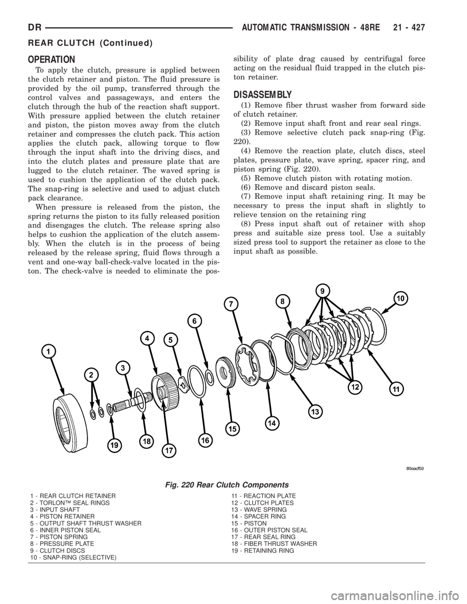
(1) Remove fiber thrust washer from forward side
of clutch retainer.
(2) Remove input shaft front and rear seal rings.
(3) Remove selective clutch pack snap-ring (Fig.
220).
(4) Remove the reaction plate, clutch discs, steel
plates, pressure plate, wave spring, spacer ring, and
piston spring (Fig. 220).
(5) Remove clutch piston with rotating motion.
(6) Remove and discard piston seals.
(7) Remove input shaft retaining ring. It may be
necessary to press the input shaft in slightly to
relieve tension on the retaining ring
(8) Press input shaft out of retainer with shop
press and suitable size press tool. Use a suitably
sized press tool to support the retainer as close to the
input shaft as possible.
Fig. 220 Rear Clutch Components
1 - REAR CLUTCH RETAINER 11 - REACTION PLATE
2 - TORLONŸ SEAL RINGS 12 - CLUTCH PLATES
3 - INPUT SHAFT 13 - WAVE SPRING
4 - PISTON RETAINER 14 - SPACER RING
5 - OUTPUT SHAFT THRUST WASHER 15 - PISTON
6 - INNER PISTON SEAL 16 - OUTER PISTON SEAL
7 - PISTON SPRING 17 - REAR SEAL RING
8 - PRESSURE PLATE 18 - FIBER THRUST WASHER
9 - CLUTCH DISCS 19 - RETAINING RING
10 - SNAP-RING (SELECTIVE)
DRAUTOMATIC TRANSMISSION - 48RE 21 - 427
REAR CLUTCH (Continued)
Page 2267 of 2895
CLEANING
Clean the clutch components with solvent and dry
them with compressed air. Do not use rags or shop
towels to dry any of the clutch parts. Lint from such
materials will adhere to component surfaces and
could restrict or block fluid passages after assembly.
INSPECTION
Replace the clutch discs if warped, worn, scored,
burned/charred, the lugs are damaged, or if the fac-
ing is flaking off. Replace the top and bottom pres-
sure plates if scored, warped, or cracked. Be sure the
driving lugs on the pressure and clutch plates are
also in good condition. The lugs must not be bent,
cracked or damaged in any way.
Replace the piston spring and wave spring if either
part is distorted, warped or broken.
Check the lug grooves in the clutch retainer. The
clutch and pressure plates should slide freely in the
slots. Replace the retainer if the grooves are worn or
damaged. Also check action of the check balls in the
retainer and piston. Each check ball must move
freely and not stick.
Replace the retainer bushing if worn, scored, or
doubt exists about bushing condition.
Inspect the piston and retainer seal surfaces for
nicks or scratches. Minor scratches can be removed
with crocus cloth. However, replace the piston and/or
retainer if the seal surfaces are seriously scored.
Check condition of the fiber thrust washer and
metal output shaft thrust washer. Replace either
washer if worn or damaged.
Check condition of the seal rings on the input shaft
and clutch retainer hub. Replace the seal rings only
if worn, distorted, or damaged. The input shaft front
seal ring is teflon with chamfered ends. The rear ring
is metal with interlocking ends.
Check the input shaft for wear, or damage. Replace
the shaft if worn, scored or damaged in any way.
ASSEMBLY
(1) Soak clutch discs in transmission fluid while
assembling other clutch parts.
(2) Install new seal rings on clutch retainer hub
and input shaft if necessary.
(a) Be sure clutch hub seal ring is fully seated in
groove and is not twisted.
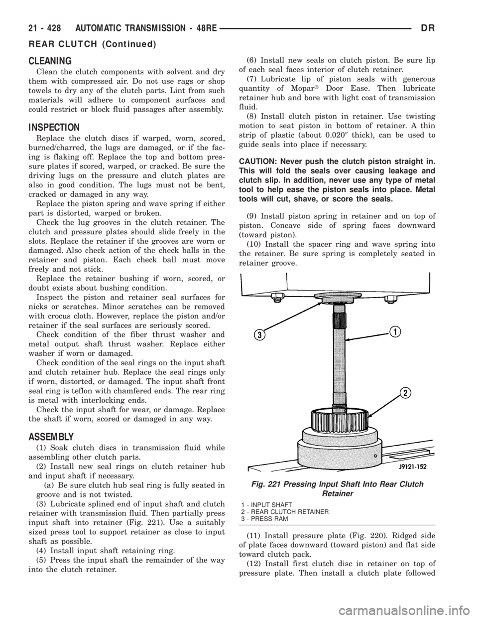
(3) Lubricate splined end of input shaft and clutch
retainer with transmission fluid. Then partially press
input shaft into retainer (Fig. 221). Use a suitably
sized press tool to support retainer as close to input
shaft as possible.
(4) Install input shaft retaining ring.
(5) Press the input shaft the remainder of the way
into the clutch retainer.(6) Install new seals on clutch piston. Be sure lip
of each seal faces interior of clutch retainer.
(7) Lubricate lip of piston seals with generous
quantity of MopartDoor Ease. Then lubricate
retainer hub and bore with light coat of transmission
fluid.
(8) Install clutch piston in retainer. Use twisting
motion to seat piston in bottom of retainer. A thin
strip of plastic (about 0.0209thick), can be used to
guide seals into place if necessary.
CAUTION: Never push the clutch piston straight in.
This will fold the seals over causing leakage and
clutch slip. In addition, never use any type of metal
tool to help ease the piston seals into place. Metal
tools will cut, shave, or score the seals.
(9) Install piston spring in retainer and on top of
piston. Concave side of spring faces downward
(toward piston).
(10) Install the spacer ring and wave spring into
the retainer. Be sure spring is completely seated in
retainer groove.
(11) Install pressure plate (Fig. 220). Ridged side
of plate faces downward (toward piston) and flat side
toward clutch pack.
(12) Install first clutch disc in retainer on top of
pressure plate. Then install a clutch plate followed
Fig. 221 Pressing Input Shaft Into Rear Clutch
Retainer
1 - INPUT SHAFT
2 - REAR CLUTCH RETAINER
3 - PRESS RAM
21 - 428 AUTOMATIC TRANSMISSION - 48REDR
REAR CLUTCH (Continued)
Page 2273 of 2895
in an incorrect T.V. cable adjustment.Slide the
sheath of the T.V. cable (D) back and forth until the
centerlines of the T.V. cable end (B) and the throttle
bell crank lever (C) are aligned within one millimeter
(1mm) (Fig. 232).
(7) While holding the T.V. cable in the set position
push the T.V. cable lock (A) into the down position
(Fig. 232). This will lock the present T.V. cable
adjustment.
NOTE: Be sure that as the cable is pulled forward
and centered on the throttle lever stud, the cable
housing moves smoothly with the cable. Due to the
angle at which the cable housing enters the spring
housing, the cable housing may bind slightly and
create an incorrect adjustment.
(8) Reconnect the T.V. cable (B) to the throttle
bellcrank lever (C).
(9) Check cable adjustment. Verify transmission
throttle lever and lever on throttle body move simul-
taneously.
TORQUE CONVERTER
DESCRIPTION
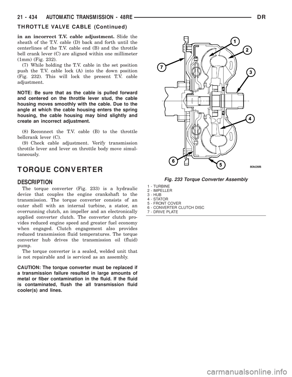
The torque converter (Fig. 233) is a hydraulic
device that couples the engine crankshaft to the
transmission. The torque converter consists of an
outer shell with an internal turbine, a stator, an
overrunning clutch, an impeller and an electronically
applied converter clutch. The converter clutch pro-
vides reduced engine speed and greater fuel economy
when engaged. Clutch engagement also provides
reduced transmission fluid temperatures. The torque
converter hub drives the transmission oil (fluid)
pump.
The torque converter is a sealed, welded unit that
is not repairable and is serviced as an assembly.
CAUTION: The torque converter must be replaced if
a transmission failure resulted in large amounts of
metal or fiber contamination in the fluid. If the fluid
is contaminated, flush the all transmission fluid
cooler(s) and lines.
Fig. 233 Torque Converter Assembly
1 - TURBINE
2 - IMPELLER
3 - HUB
4-STATOR
5 - FRONT COVER
6 - CONVERTER CLUTCH DISC
7 - DRIVE PLATE
21 - 434 AUTOMATIC TRANSMISSION - 48REDR
THROTTLE VALVE CABLE (Continued)