2003 DODGE RAM light
[x] Cancel search: lightPage 2277 of 2895
OPERATION
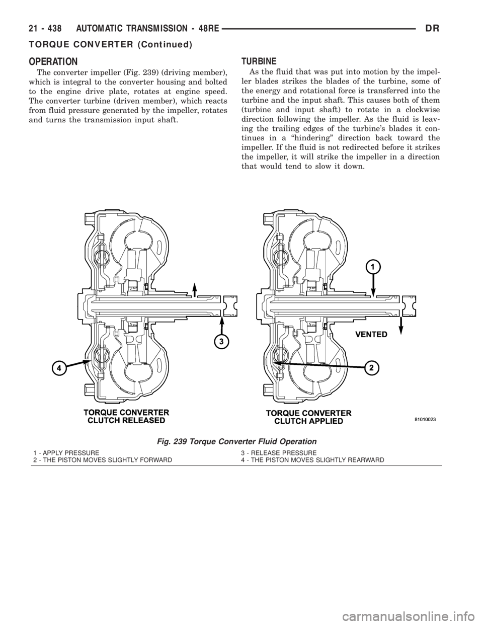
The converter impeller (Fig. 239) (driving member),
which is integral to the converter housing and bolted
to the engine drive plate, rotates at engine speed.
The converter turbine (driven member), which reacts
from fluid pressure generated by the impeller, rotates
and turns the transmission input shaft.
TURBINE
As the fluid that was put into motion by the impel-
ler blades strikes the blades of the turbine, some of
the energy and rotational force is transferred into the
turbine and the input shaft. This causes both of them
(turbine and input shaft) to rotate in a clockwise
direction following the impeller. As the fluid is leav-
ing the trailing edges of the turbine's blades it con-
tinues in a ªhinderingº direction back toward the
impeller. If the fluid is not redirected before it strikes
the impeller, it will strike the impeller in a direction
that would tend to slow it down.
Fig. 239 Torque Converter Fluid Operation
1 - APPLY PRESSURE 3 - RELEASE PRESSURE
2 - THE PISTON MOVES SLIGHTLY FORWARD 4 - THE PISTON MOVES SLIGHTLY REARWARD
21 - 438 AUTOMATIC TRANSMISSION - 48REDR
TORQUE CONVERTER (Continued)
Page 2315 of 2895
3-4 ACCUMULATOR HOUSING
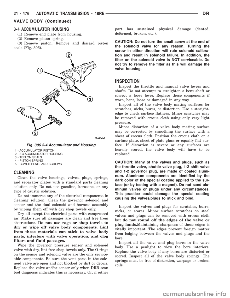
(1) Remove end plate from housing.
(2) Remove piston spring.
(3) Remove piston. Remove and discard piston
seals (Fig. 306).
CLEANING
Clean the valve housings, valves, plugs, springs,
and separator plates with a standard parts cleaning
solution only. Do not use gasoline, kerosene, or any
type of caustic solution.
Do not immerse any of the electrical components in
cleaning solution. Clean the governor solenoid and
sensor and the dual solenoid and harness assembly
by wiping them off with dry shop towels only.
Dry all except the electrical parts with compressed
air. Make sure all passages are clean and free from
obstructions.Do not use rags or shop towels to
dry or wipe off valve body components. Lint
from these materials can stick to valve body
parts, interfere with valve operation, and clog
filters and fluid passages.
Wipe the governor pressure sensor and solenoid
valve with dry, lint free shop towels only. The O-rings
on the sensor and solenoid valve are the only service-
able components. Be sure the vent ports in the sole-
noid valve are open and not blocked by dirt or debris.
Replace the valve and/or sensor only when DRB scan
tool diagnosis indicates this is necessary. Or, if eitherpart has sustained physical damage (dented,
deformed, broken, etc.).
CAUTION: Do not turn the small screw at the end of
the solenoid valve for any reason. Turning the
screw in either direction will ruin solenoid calibra-
tion and result in solenoid failure. In addition, the
filter on the solenoid valve is NOT serviceable. Do
not try to remove the filter as this will damage the
valve housing.
INSPECTION
Inspect the throttle and manual valve levers and
shafts. Do not attempt to straighten a bent shaft or
correct a loose lever. Replace these components if
worn, bent, loose or damaged in any way.
Inspect all of the valve body mating surfaces for
scratches, nicks, burrs, or distortion. Use a straight-
edge to check surface flatness. Minor scratches may
be removed with crocus cloth using only very light
pressure.
Minor distortion of a valve body mating surface
may be corrected by smoothing the surface with a
sheet of crocus cloth. Position the crocus cloth on a
surface plate, sheet of plate glass or equally flat sur-
face. If distortion is severe or any surfaces are
heavily scored, the valve body will have to be
replaced.
CAUTION: Many of the valves and plugs, such as
the throttle valve, shuttle valve plug, 1-2 shift valve
and 1-2 governor plug, are made of coated alumi-
num. Aluminum components are identified by the
dark color of the special coating applied to the sur-
face (or by testing with a magnet). Do not sand alu-
minum valves or plugs under any circumstances.
This practice could damage the special coating
causing the valves/plugs to stick and bind.
Inspect the valves and plugs for scratches, burrs,
nicks, or scores. Minor surface scratches on steel
valves and plugs can be removed with crocus cloth
butdo not round off the edges of the valve or
plug lands.Maintaining sharpness of these edges is
vitally important. The edges prevent foreign matter
from lodging between the valves and plugs and the
bore.
Inspect all the valve and plug bores in the valve
body. Use a penlight to view the bore interiors.
Replace the valve body if any bores are distorted or
scored. Inspect all of the valve body springs. The
springs must be free of distortion, warpage or broken
coils.
Fig. 306 3-4 Accumulator and Housing
1 - ACCUMULATOR PISTON
2 - 3-4 ACCUMULATOR HOUSING
3 - TEFLON SEALS
4 - PISTON SPRING
5 - COVER PLATE AND SCREWS
21 - 476 AUTOMATIC TRANSMISSION - 48REDR
VALVE BODY (Continued)
Page 2324 of 2895
VALVE BODY FINAL
(1) Install boost valve, valve spring, retainer and
cover plate. Tighten cover plate screws to 4 N´m (35
in. lbs.) torque.
(2) Insert manual lever detent spring in upper
housing.
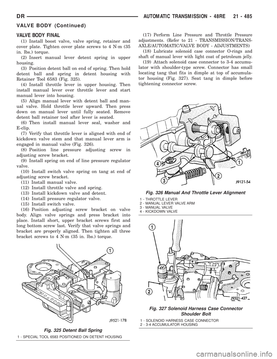
(3) Position detent ball on end of spring. Then hold
detent ball and spring in detent housing with
Retainer Tool 6583 (Fig. 325).
(4) Install throttle lever in upper housing. Then
install manual lever over throttle lever and start
manual lever into housing.
(5) Align manual lever with detent ball and man-
ual valve. Hold throttle lever upward. Then press
down on manual lever until fully seated. Remove
detent ball retainer tool after lever is seated.
(6) Then install manual lever seal, washer and
E-clip.
(7) Verify that throttle lever is aligned with end of
kickdown valve stem and that manual lever arm is
engaged in manual valve (Fig. 326).
(8) Position line pressure adjusting screw in
adjusting screw bracket.
(9) Install spring on end of line pressure regulator
valve.
(10) Install switch valve spring on tang at end of
adjusting screw bracket.
(11) Install manual valve.
(12) Install throttle valve and spring.
(13) Install kickdown valve and detent.
(14) Install pressure regulator valve.
(15) Install switch valve.
(16) Position adjusting screw bracket on valve
body. Align valve springs and press bracket into
place. Install short, upper bracket screws first and
long bottom screw last. Verify that valve springs and
bracket are properly aligned. Then tighten all three
bracket screws to 4 N´m (35 in. lbs.) torque.(17)
Perform Line Pressure and Throttle Pressure
adjustments. (Refer to 21 - TRANSMISSION/TRANS-
AXLE/AUTOMATIC/VALVE BODY - ADJUSTMENTS)
(18)Lubricate solenoid case connector O-rings and
shaft of manual lever with light coat of petroleum jelly.
(19) Attach solenoid case connector to 3-4 accumu-
lator with shoulder-type screw. Connector has small
locating tang that fits in dimple at top of accumula-
tor housing (Fig. 327). Seat tang in dimple before
tightening connector screw.
Fig. 325 Detent Ball Spring
1 - SPECIAL TOOL 6583 POSITIONED ON DETENT HOUSING
Fig. 326 Manual And Throttle Lever Alignment
1 - THROTTLE LEVER
2 - MANUAL LEVER VALVE ARM
3 - MANUAL VALVE
4 - KICKDOWN VALVE
Fig. 327 Solenoid Harness Case Connector
Shoulder Bolt
1 - SOLENOID HARNESS CASE CONNECTOR
2 - 3-4 ACCUMULATOR HOUSING
DRAUTOMATIC TRANSMISSION - 48RE 21 - 485
VALVE BODY (Continued)
Page 2336 of 2895
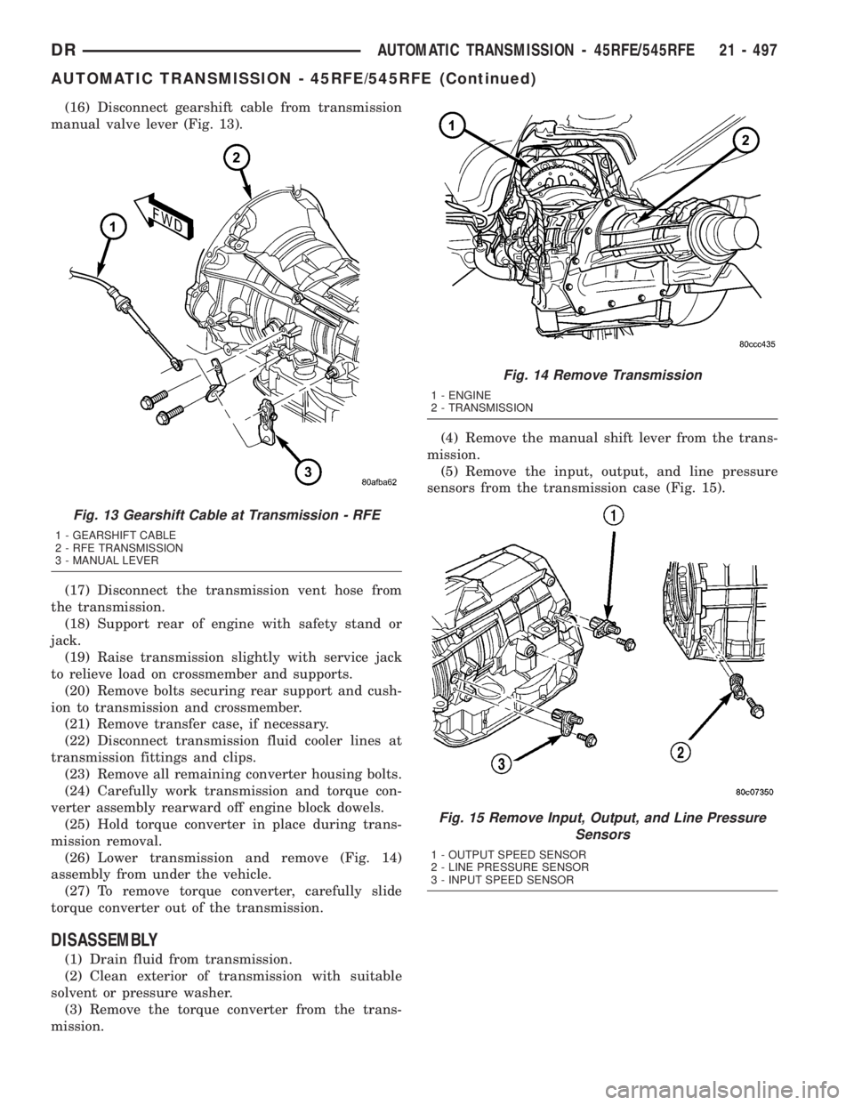
(16) Disconnect gearshift cable from transmission
manual valve lever (Fig. 13).
(17) Disconnect the transmission vent hose from
the transmission.
(18) Support rear of engine with safety stand or
jack.
(19) Raise transmission slightly with service jack
to relieve load on crossmember and supports.
(20) Remove bolts securing rear support and cush-
ion to transmission and crossmember.
(21) Remove transfer case, if necessary.
(22) Disconnect transmission fluid cooler lines at
transmission fittings and clips.
(23) Remove all remaining converter housing bolts.
(24) Carefully work transmission and torque con-
verter assembly rearward off engine block dowels.
(25) Hold torque converter in place during trans-
mission removal.
(26) Lower transmission and remove (Fig. 14)
assembly from under the vehicle.
(27) To remove torque converter, carefully slide
torque converter out of the transmission.
DISASSEMBLY
(1) Drain fluid from transmission.
(2) Clean exterior of transmission with suitable
solvent or pressure washer.
(3) Remove the torque converter from the trans-
mission.(4) Remove the manual shift lever from the trans-
mission.
(5) Remove the input, output, and line pressure
sensors from the transmission case (Fig. 15).
Fig. 13 Gearshift Cable at Transmission - RFE
1 - GEARSHIFT CABLE
2 - RFE TRANSMISSION
3 - MANUAL LEVER
Fig. 14 Remove Transmission
1 - ENGINE
2 - TRANSMISSION
Fig. 15 Remove Input, Output, and Line Pressure
Sensors
1 - OUTPUT SPEED SENSOR
2 - LINE PRESSURE SENSOR
3 - INPUT SPEED SENSOR
DRAUTOMATIC TRANSMISSION - 45RFE/545RFE 21 - 497
AUTOMATIC TRANSMISSION - 45RFE/545RFE (Continued)
Page 2349 of 2895
(55) Install the manual shift lever from the trans-
mission. Torque the retaining cross-bolt to 16 N´m
(140 in.lbs.).
INSTALLATION
(1) Check torque converter hub and hub drive flats
for sharp edges burrs, scratches, or nicks. Polish the
hub and flats with 320/400 grit paper and crocus
cloth if necessary. Verify that the converter hub
o-ring is properly installed and is free of any debris.
The hub must be smooth to avoid damaging pump
seal at installation.
(2) If a replacement transmission is being
installed, transfer any components necessary, such as
the manual shift lever and shift cable bracket, from
the original transmission onto the replacement trans-
mission.
(3) Lubricate oil pump seal lip with transmission
fluid.
(4) Align converter and oil pump.
(5) Carefully insert converter in oil pump. Then
rotate converter back and forth until fully seated in
pump gears.
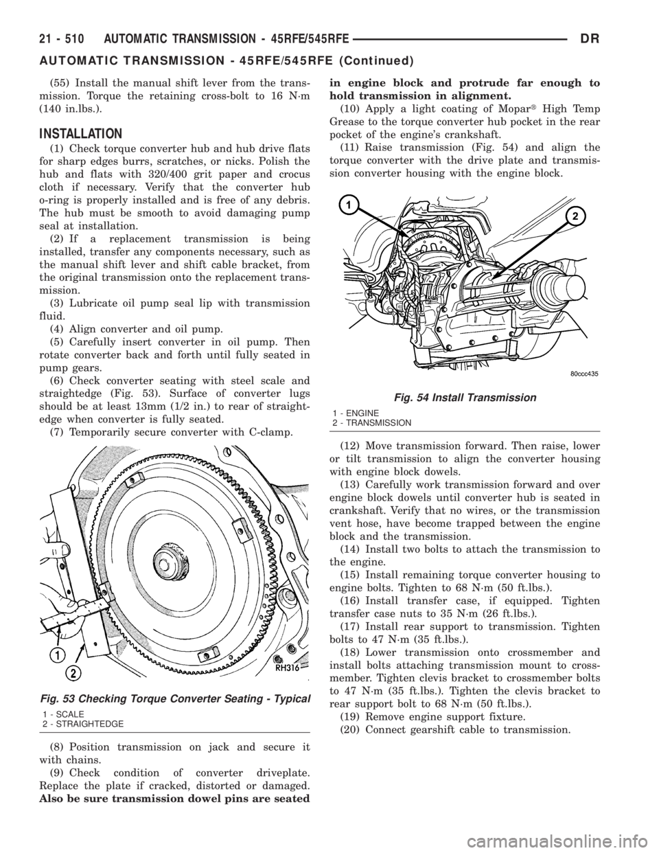
(6) Check converter seating with steel scale and
straightedge (Fig. 53). Surface of converter lugs
should be at least 13mm (1/2 in.) to rear of straight-
edge when converter is fully seated.
(7) Temporarily secure converter with C-clamp.
(8) Position transmission on jack and secure it
with chains.
(9) Check condition of converter driveplate.
Replace the plate if cracked, distorted or damaged.
Also be sure transmission dowel pins are seatedin engine block and protrude far enough to
hold transmission in alignment.
(10) Apply a light coating of MopartHigh Temp
Grease to the torque converter hub pocket in the rear
pocket of the engine's crankshaft.
(11) Raise transmission (Fig. 54) and align the
torque converter with the drive plate and transmis-
sion converter housing with the engine block.
(12) Move transmission forward. Then raise, lower
or tilt transmission to align the converter housing
with engine block dowels.
(13) Carefully work transmission forward and over
engine block dowels until converter hub is seated in
crankshaft. Verify that no wires, or the transmission
vent hose, have become trapped between the engine
block and the transmission.
(14) Install two bolts to attach the transmission to
the engine.
(15) Install remaining torque converter housing to
engine bolts. Tighten to 68 N´m (50 ft.lbs.).
(16) Install transfer case, if equipped. Tighten
transfer case nuts to 35 N´m (26 ft.lbs.).
(17) Install rear support to transmission. Tighten
bolts to 47 N´m (35 ft.lbs.).
(18) Lower transmission onto crossmember and
install bolts attaching transmission mount to cross-
member. Tighten clevis bracket to crossmember bolts
to 47 N´m (35 ft.lbs.). Tighten the clevis bracket to
rear support bolt to 68 N´m (50 ft.lbs.).
(19) Remove engine support fixture.
(20) Connect gearshift cable to transmission.
Fig. 53 Checking Torque Converter Seating - Typical
1 - SCALE
2 - STRAIGHTEDGE
Fig. 54 Install Transmission
1 - ENGINE
2 - TRANSMISSION
21 - 510 AUTOMATIC TRANSMISSION - 45RFE/545RFEDR
AUTOMATIC TRANSMISSION - 45RFE/545RFE (Continued)
Page 2382 of 2895
(10) Separate filter from valve body and oil pump
and pour fluid in filter into drain pan.
(11) Remove and discard the oil filter seal from the
bottom of the oil pump.
(12) If replacing the cooler return filter, use Oil
Filter Wrench 8321 to remove the filter from the
transmission.
(13)
Dispose of used trans fluid and filter(s) properly.
INSPECTION
Inspect bottom of pan and magnet for excessive
amounts of metal. A light coating of clutch material
on the bottom of the pan does not indicate a problem
unless accompanied by a slipping condition or shift
lag. If fluid and pan are contaminated with excessive
amounts of debris, refer to the diagnosis section of
this group.
CLEANING
(1)Using a suitable solvent, clean pan and magnet.
(2) Using a suitable gasket scraper, clean original
sealing material from surface of transmission case
and the transmission pan.
INSTALLATION
(1) Install a new primary oil filter seal in the oil
pump inlet bore. Seat the seal in the bore with the
butt end of a hammer, or other suitable tool.CAUTION: The primary oil filter seal MUST be fully
installed flush against the oil pump body. DO NOT
install the seal onto the filter neck and attempt to
install the filter and seal as an assembly. Damage to
the transmission will result.
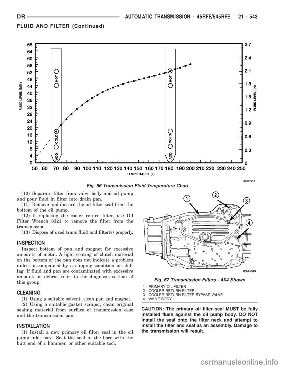
Fig. 66 Transmission Fluid Temperature Chart
Fig. 67 Transmission Filters - 4X4 Shown
1 - PRIMARY OIL FILTER
2 - COOLER RETURN FILTER
3 - COOLER RETURN FILTER BYPASS VALVE
4 - VALVE BODY
DRAUTOMATIC TRANSMISSION - 45RFE/545RFE 21 - 543
FLUID AND FILTER (Continued)
Page 2405 of 2895
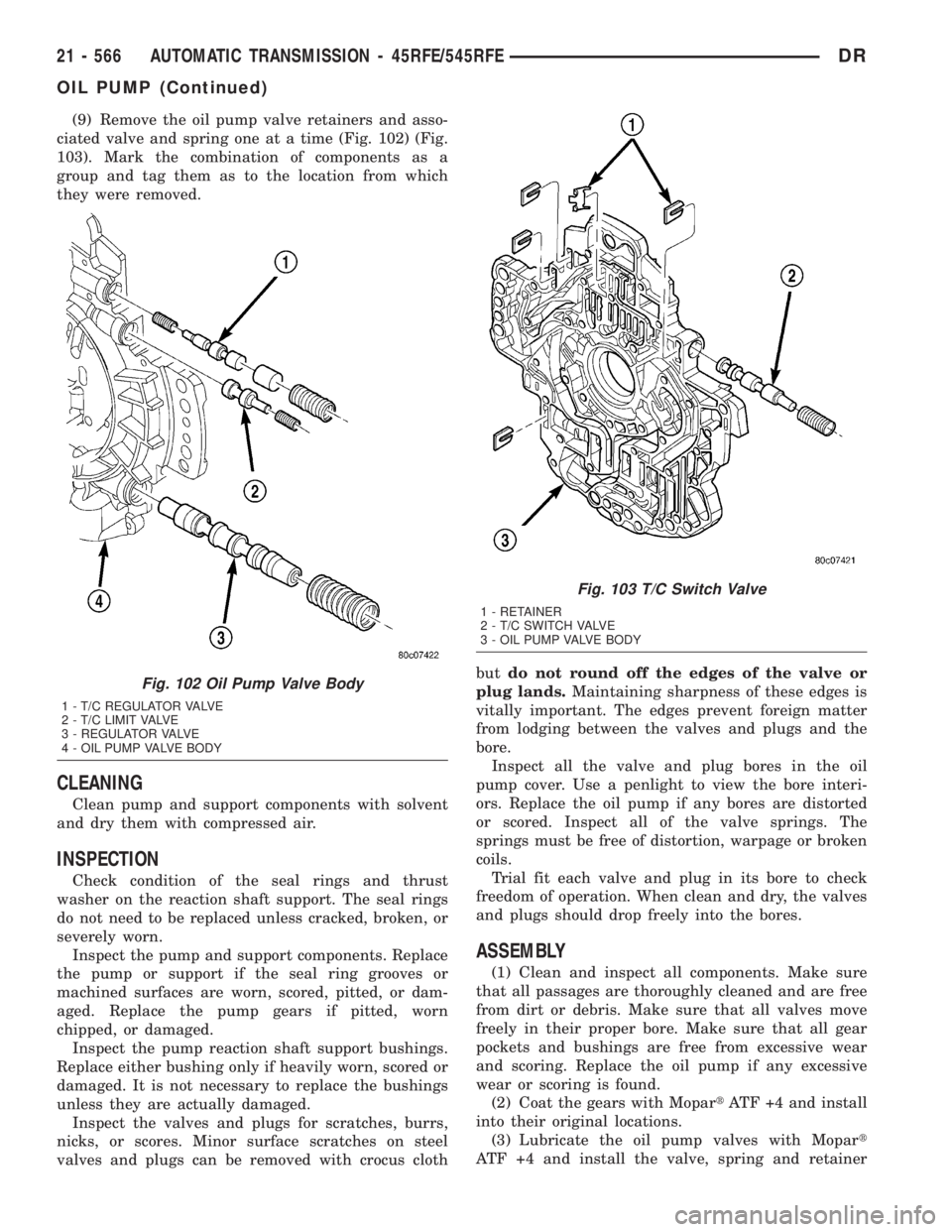
(9) Remove the oil pump valve retainers and asso-
ciated valve and spring one at a time (Fig. 102) (Fig.
103). Mark the combination of components as a
group and tag them as to the location from which
they were removed.
CLEANING
Clean pump and support components with solvent
and dry them with compressed air.
INSPECTION
Check condition of the seal rings and thrust
washer on the reaction shaft support. The seal rings
do not need to be replaced unless cracked, broken, or
severely worn.
Inspect the pump and support components. Replace
the pump or support if the seal ring grooves or
machined surfaces are worn, scored, pitted, or dam-
aged. Replace the pump gears if pitted, worn
chipped, or damaged.
Inspect the pump reaction shaft support bushings.
Replace either bushing only if heavily worn, scored or
damaged. It is not necessary to replace the bushings
unless they are actually damaged.
Inspect the valves and plugs for scratches, burrs,
nicks, or scores. Minor surface scratches on steel
valves and plugs can be removed with crocus clothbutdo not round off the edges of the valve or
plug lands.Maintaining sharpness of these edges is
vitally important. The edges prevent foreign matter
from lodging between the valves and plugs and the
bore.
Inspect all the valve and plug bores in the oil
pump cover. Use a penlight to view the bore interi-
ors. Replace the oil pump if any bores are distorted
or scored. Inspect all of the valve springs. The
springs must be free of distortion, warpage or broken
coils.
Trial fit each valve and plug in its bore to check
freedom of operation. When clean and dry, the valves
and plugs should drop freely into the bores.
ASSEMBLY
(1) Clean and inspect all components. Make sure
that all passages are thoroughly cleaned and are free
from dirt or debris. Make sure that all valves move
freely in their proper bore. Make sure that all gear
pockets and bushings are free from excessive wear
and scoring. Replace the oil pump if any excessive
wear or scoring is found.
(2) Coat the gears with MopartATF +4 and install
into their original locations.
(3) Lubricate the oil pump valves with Mopart
ATF +4 and install the valve, spring and retainer
Fig. 102 Oil Pump Valve Body
1 - T/C REGULATOR VALVE
2 - T/C LIMIT VALVE
3 - REGULATOR VALVE
4 - OIL PUMP VALVE BODY
Fig. 103 T/C Switch Valve
1 - RETAINER
2 - T/C SWITCH VALVE
3 - OIL PUMP VALVE BODY
21 - 566 AUTOMATIC TRANSMISSION - 45RFE/545RFEDR
OIL PUMP (Continued)
Page 2407 of 2895
OVERDRIVE SWITCH
DESCRIPTION
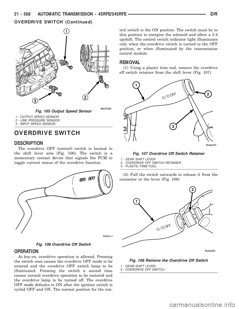
The overdrive OFF (control) switch is located in
the shift lever arm (Fig. 106). The switch is a
momentary contact device that signals the PCM to
toggle current status of the overdrive function.
OPERATION
At key-on, overdrive operation is allowed. Pressing
the switch once causes the overdrive OFF mode to be
entered and the overdrive OFF switch lamp to be
illuminated. Pressing the switch a second time
causes normal overdrive operation to be restored and
the overdrive lamp to be turned off. The overdrive
OFF mode defaults to ON after the ignition switch is
cycled OFF and ON. The normal position for the con-trol switch is the ON position. The switch must be in
this position to energize the solenoid and allow a 3-4
upshift. The control switch indicator light illuminates
only when the overdrive switch is turned to the OFF
position, or when illuminated by the transmission
control module.
REMOVAL
(1) Using a plastic trim tool, remove the overdrive
off switch retainer from the shift lever (Fig. 107).
(2) Pull the switch outwards to release it from the
connector in the lever (Fig. 108)
Fig. 105 Output Speed Sensor
1 - OUTPUT SPEED SENSOR
2 - LINE PRESSURE SENSOR
3 - INPUT SPEED SENSOR
Fig. 106 Overdrive Off Switch
Fig. 107 Overdrive Off Switch Retainer
1 - GEAR SHIFT LEVER
2 - OVERDRIVE OFF SWITCH RETAINER
3 - PLASTIC TRIM TOOL
Fig. 108 Remove the Overdrive Off Switch
1 - GEAR SHIFT LEVER
2 - OVERDRIVE OFF SWITCH
21 - 568 AUTOMATIC TRANSMISSION - 45RFE/545RFEDR
OVERDRIVE SWITCH (Continued)