2003 DODGE RAM light
[x] Cancel search: lightPage 2799 of 2895
DISTRIBUTION
TABLE OF CONTENTS
page page
AIR OUTLETS
REMOVAL - PANEL OUTLETS.............24
INSTALLATION - PANEL OUTLETS..........24
BLEND DOOR
REMOVAL.............................24
INSTALLATION.........................25
BLOWER MOTOR
DESCRIPTION.........................25
OPERATION...........................25
DIAGNOSIS AND TESTING - BLOWER
MOTOR .............................26
REMOVAL.............................26
INSTALLATION.........................26
DEFROST DOOR
REMOVAL - DEFROST DOOR.............27
INSTALLATION - DEFROST DOOR..........27
FLOOR DISTRIBUTION DUCTS
REMOVAL.............................27INSTALLATION.........................27
HVAC HOUSING
REMOVAL.............................27
DISASSEMBLY.........................28
ASSEMBLY............................28
INSTALLATION.........................29
INSTRUMENT PANEL DUCTS
REMOVAL.............................29
INSTALLATION.........................29
MODE DOOR
REMOVAL - FLOOR - DEFROST DOOR......30
INSTALLATION - FLOOR - DEFROST DOOR . . 30
RECIRC DOOR
REMOVAL.............................30
INSTALLATION.........................30
AIR OUTLETS
REMOVAL - PANEL OUTLETS
(1) Use a trim stick or another suitable wide flat-
bladed tool to gently pry the panel outlet grill out of
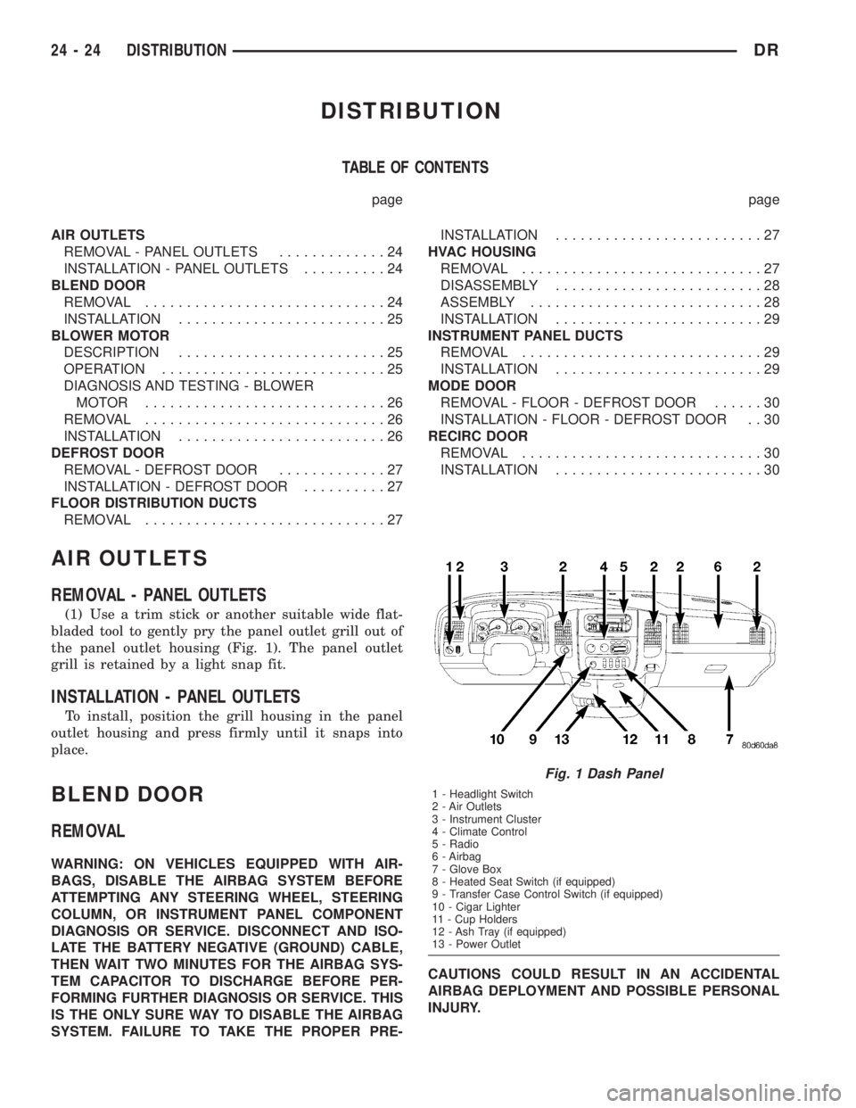
the panel outlet housing (Fig. 1). The panel outlet
grill is retained by a light snap fit.
INSTALLATION - PANEL OUTLETS
To install, position the grill housing in the panel
outlet housing and press firmly until it snaps into
place.
BLEND DOOR
REMOVAL
WARNING: ON VEHICLES EQUIPPED WITH AIR-
BAGS, DISABLE THE AIRBAG SYSTEM BEFORE
ATTEMPTING ANY STEERING WHEEL, STEERING
COLUMN, OR INSTRUMENT PANEL COMPONENT
DIAGNOSIS OR SERVICE. DISCONNECT AND ISO-
LATE THE BATTERY NEGATIVE (GROUND) CABLE,
THEN WAIT TWO MINUTES FOR THE AIRBAG SYS-
TEM CAPACITOR TO DISCHARGE BEFORE PER-
FORMING FURTHER DIAGNOSIS OR SERVICE. THIS
IS THE ONLY SURE WAY TO DISABLE THE AIRBAG
SYSTEM. FAILURE TO TAKE THE PROPER PRE-CAUTIONS COULD RESULT IN AN ACCIDENTAL
AIRBAG DEPLOYMENT AND POSSIBLE PERSONAL
INJURY.
Fig. 1 Dash Panel
1 - Headlight Switch
2 - Air Outlets
3 - Instrument Cluster
4 - Climate Control
5 - Radio
6 - Airbag
7 - Glove Box
8 - Heated Seat Switch (if equipped)
9 - Transfer Case Control Switch (if equipped)
10 - Cigar Lighter
11 - Cup Holders
12 - Ash Tray (if equipped)
13 - Power Outlet
24 - 24 DISTRIBUTIONDR
Page 2807 of 2895
STANDARD PROCEDURE
STANDARD PROCEDURE - REFRIGERANT
SYSTEM EVACUATE...................51
STANDARD PROCEDURE- REFRIGERANT
RECOVERY..........................52
STANDARD PROCEDURE- REFRIGERANT
SYSTEM CHARGE.....................52
REFRIGERANT LINE COUPLER
DESCRIPTION.........................52OPERATION...........................52
REMOVAL.............................52
INSTALLATION.........................53
REFRIGERANT OIL
DESCRIPTION.........................54
OPERATION...........................54
STANDARD PROCEDURE - REFRIGERANT
OIL LEVEL...........................54
PLUMBING
DESCRIPTION - REFRIGERANT LINE
The refrigerant lines and hoses are used to carry
the refrigerant between the various air conditioning
system components. A barrier hose design with a
nylon tube, which is sandwiched between rubber lay-
ers, is used for the R-134a air conditioning system on
this vehicle. This nylon tube helps to further contain
the R-134a refrigerant, which has a smaller molecu-
lar structure than R-12 refrigerant. The ends of the
refrigerant hoses are made from lightweight alumi-
num or steel, and commonly use braze-less fittings.
Any kinks or sharp bends in the refrigerant plumb-
ing will reduce the capacity of the entire air condi-
tioning system. Kinks and sharp bends reduce the
flow of refrigerant in the system. A good rule for the
flexible hose refrigerant lines is to keep the radius of
all bends at least ten times the diameter of the hose.
In addition, the flexible hose refrigerant lines should
be routed so they are at least 80 millimeters (3
inches) from an exhaust manifold.
OPERATION- REFRIGERANT LINES
High pressures are produced in the refrigerant sys-
tem when the air conditioning compressor is operat-
ing. Extreme care must be exercised to make sure
that each of the refrigerant system connections is
pressure-tight and leak free. It is a good practice to
inspect all flexible hose refrigerant lines at least once
a year to make sure they are in good condition and
properly routed.
The refrigerant lines and hoses are coupled with
other components of the HVAC system with either 3
O-ring spring lock couplings or dual axes seals.
The refrigerant lines and hoses cannot be repaired
and, if faulty or damaged, they must be replaced.
WARNING
SERVICE WARNINGS
WARNING: THE AIR CONDITIONING SYSTEM CON-
TAINS REFRIGERANT UNDER HIGH PRESSURE.
SEVERE PERSONAL INJURY MAY RESULT FROM
IMPROPER SERVICE PROCEDURES. REPAIRS
SHOULD ONLY BE PERFORMED BY QUALIFIED
SERVICE PERSONNEL.
AVOID BREATHING THE REFRIGERANT AND
REFRIGERANT OIL VAPOR OR MIST. EXPOSURE
MAY IRRITATE THE EYES, NOSE, AND/OR THROAT.
WEAR EYE PROTECTION WHEN SERVICING THE
AIR CONDITIONING REFRIGERANT SYSTEM. SERI-
OUS EYE INJURY CAN RESULT FROM DIRECT
CONTACT WITH THE REFRIGERANT. IF EYE CON-
TACT OCCURS, SEEK MEDICAL ATTENTION IMME-
DIATELY.
DO NOT EXPOSE THE REFRIGERANT TO OPEN
FLAME. POISONOUS GAS IS CREATED WHEN
REFRIGERANT IS BURNED. AN ELECTRONIC LEAK
DETECTOR IS RECOMMENDED.
IF ACCIDENTAL SYSTEM DISCHARGE OCCURS,
VENTILATE THE WORK AREA BEFORE RESUMING
SERVICE. LARGE AMOUNTS OF REFRIGERANT
RELEASED IN A CLOSED WORK AREA WILL DIS-
PLACE THE OXYGEN AND CAUSE SUFFOCATION.
THE EVAPORATION RATE OF R-134a REFRIGER-
ANT AT AVERAGE TEMPERATURE AND ALTITUDE
IS EXTREMELY HIGH. AS A RESULT, ANYTHING
THAT COMES IN CONTACT WITH THE REFRIGER-
ANT WILL FREEZE. ALWAYS PROTECT THE SKIN
OR DELICATE OBJECTS FROM DIRECT CONTACT
WITH THE REFRIGERANT.
THE R-134a SERVICE EQUIPMENT OR THE VEHI-
CLE REFRIGERANT SYSTEM SHOULD NOT BE
PRESSURE TESTED OR LEAK TESTED WITH COM-
PRESSED AIR. SOME MIXTURES OF AIR AND
R-134a HAVE BEEN SHOWN TO BE COMBUSTIBLE
AT ELEVATED PRESSURES. THESE MIXTURES ARE
POTENTIALLY DANGEROUS, AND MAY RESULT IN
FIRE OR EXPLOSION CAUSING INJURY OR PROP-
ERTY DAMAGE.
24 - 32 PLUMBINGDR
Page 2823 of 2895
(1) Insert the evaporator coil into the bottom of the
HVAC housing. Make sure that the evaporator drain
is clean and unrestricted and evaporator deflector
shield is also installed.
(2) Reassemble and reinstall the HVAC housing in
the vehicle. (Refer to 24 - HEATING & AIR CONDI-
TIONING/DISTRIBUTION/HVAC HOUSING -
ASSEMBLY) (Refer to 24 - HEATING & AIR CON-
DITIONING/DISTRIBUTION/HVAC HOUSING -
INSTALLATION)
NOTE: If the evaporator is replaced, add 60 millili-
ters (2 fluid ounces) of refrigerant oil to the refrig-
erant system.
A/C ORIFICE TUBE
DESCRIPTION
The fixed orifice tube is installed in the liquid line
between the outlet of the condenser and the inlet of
the evaporator. The fixed orifice tube is only serviced
as an integral part of the liquid line.
OPERATION
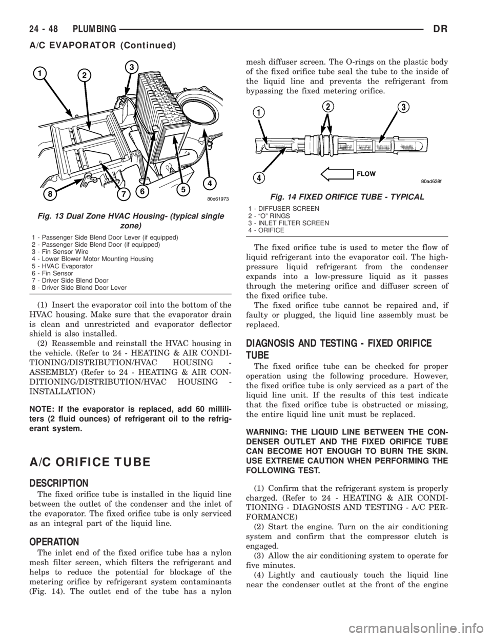
The inlet end of the fixed orifice tube has a nylon
mesh filter screen, which filters the refrigerant and
helps to reduce the potential for blockage of the
metering orifice by refrigerant system contaminants
(Fig. 14). The outlet end of the tube has a nylonmesh diffuser screen. The O-rings on the plastic body
of the fixed orifice tube seal the tube to the inside of
the liquid line and prevents the refrigerant from
bypassing the fixed metering orifice.
The fixed orifice tube is used to meter the flow of
liquid refrigerant into the evaporator coil. The high-
pressure liquid refrigerant from the condenser
expands into a low-pressure liquid as it passes
through the metering orifice and diffuser screen of
the fixed orifice tube.
The fixed orifice tube cannot be repaired and, if
faulty or plugged, the liquid line assembly must be
replaced.
DIAGNOSIS AND TESTING - FIXED ORIFICE
TUBE
The fixed orifice tube can be checked for proper
operation using the following procedure. However,
the fixed orifice tube is only serviced as a part of the
liquid line unit. If the results of this test indicate
that the fixed orifice tube is obstructed or missing,
the entire liquid line unit must be replaced.
WARNING: THE LIQUID LINE BETWEEN THE CON-
DENSER OUTLET AND THE FIXED ORIFICE TUBE
CAN BECOME HOT ENOUGH TO BURN THE SKIN.
USE EXTREME CAUTION WHEN PERFORMING THE
FOLLOWING TEST.
(1) Confirm that the refrigerant system is properly
charged. (Refer to 24 - HEATING & AIR CONDI-
TIONING - DIAGNOSIS AND TESTING - A/C PER-
FORMANCE)
(2) Start the engine. Turn on the air conditioning
system and confirm that the compressor clutch is
engaged.
(3) Allow the air conditioning system to operate for
five minutes.
(4) Lightly and cautiously touch the liquid line
near the condenser outlet at the front of the engine
Fig. 13 Dual Zone HVAC Housing- (typical single
zone)
1 - Passenger Side Blend Door Lever (if equipped)
2 - Passenger Side Blend Door (if equipped)
3 - Fin Sensor Wire
4 - Lower Blower Motor Mounting Housing
5 - HVAC Evaporator
6 - Fin Sensor
7 - Driver Side Blend Door
8 - Driver Side Blend Door Lever
Fig. 14 FIXED ORIFICE TUBE - TYPICAL
1 - DIFFUSER SCREEN
2 - ªOº RINGS
3 - INLET FILTER SCREEN
4 - ORIFICE
24 - 48 PLUMBINGDR
A/C EVAPORATOR (Continued)
Page 2826 of 2895

small amount of R-12 added to an R-134a refrigerant
system will cause compressor failure, refrigerant oil
sludge or poor air conditioning system performance.
In addition, the PolyAlkylene Glycol (PAG) synthetic
refrigerant oils used in an R-134a refrigerant system
are not compatible with the mineral-based refriger-
ant oils used in an R-12 refrigerant system.
R-134a refrigerant system service ports, service
tool couplers and refrigerant dispensing bottles have
all been designed with unique fittings to ensure that
an R-134a system is not accidentally contaminated
with the wrong refrigerant (R-12). There are also
labels posted in the engine compartment of the vehi-
cle and on the compressor identifying to service tech-
nicians that the air conditioning system is equipped
with R-134a.
DIAGNOSIS AND TESTING- REFRIGERANT
SYSTEM LEAKS
WARNING: (Refer to 24 - HEATING & AIR CONDI-
TIONING/PLUMBING - WARNING) and (Refer to 24 -
HEATING & AIR CONDITIONING/PLUMBING - CAU-
TION).
If the air conditioning system does not cool prop-
erly, the A/C system performance should be tested.
See A/C Performance in the Diagnosis and Testing
section of this group for the procedures. If the A/C
system refrigerant fill is found to be low or if the sys-
tem is empty; a leak at a refrigerant line, connector
fitting, component, or component seal is likely.
An electronic leak detector designed for R-134a
refrigerant, or a fluorescent R-134a leak detection
dye and a black light are recommended for locating
and confirming refrigerant system leaks. Refer to the
operating instructions supplied by the equipment
manufacturer for the proper care and use of this
equipment.
An oily residue on or near refrigerant system lines,
connector fittings, components, or component seals
can indicate the general location of a possible refrig-
erant leak. However, the exact leak location should
be confirmed with an electronic leak detector prior to
component repair or replacement.
To detect a leak in the refrigerant system with an
electronic leak detector, perform one of the following
procedures:
SYSTEM EMPTY
(1) Evacuate the refrigerant system (Refer to 24 -
HEATING & AIR CONDITIONING/PLUMBING/RE-
FRIGERANT - STANDARD PROCEDURE).
(2) Connect and dispense 0.283 kilograms (0.625
pounds or 10 ounces) of R-134a refrigerant into the
evacuated refrigerant system (Refer to 24 - HEAT-ING & AIR CONDITIONING/PLUMBING/REFRIG-
ERANT - STANDARD PROCEDURE).
(3) Position the vehicle in a wind-free work area.
This will aid in detecting small leaks.
(4) With the engine not running, use a electronic
R-134a leak detector and search for leaks. Because
R-134a refrigerant is heavier than air, the leak detec-
tor probe should be moved slowly along the bottom
side of all refrigerant lines, connector fittings and
components.
(5) To inspect the evaporator coil for leaks, insert
the electronic leak detector probe into the center
instrument panel outlet and the floor duct outlet. Set
the blower motor switch to the lowest speed position,
and the mode control switch in the recirculation
mode (Max-A/C).
SYSTEM LOW
(1) Position the vehicle in a wind-free work area.
This will aid in detecting small leaks.
(2) Bring the refrigerant system up to operating
temperature and pressure. This is done by allowing
the engine to run with the air conditioning system
turned on for five minutes.
(3) With the engine not running, use a electronic
R-134a leak detector and search for leaks. Because
R-134a refrigerant is heavier than air, the leak detec-
tor probe should be moved slowly along the bottom
side of all refrigerant lines, connector fittings and
components.
(4) To inspect the evaporator coil for leaks, insert
the electronic leak detector probe into the center
instrument panel outlet and the floor duct outlet. Set
the blower motor switch to the lowest speed position,
and the mode control switch in the recirculation
mode (Max-A/C).
STANDARD PROCEDURE
STANDARD PROCEDURE - REFRIGERANT
SYSTEM EVACUATE
WARNING: (Refer to 24 - HEATING & AIR CONDI-
TIONING/PLUMBING - WARNING) AND (Refer to 24 -
HEATING & AIR CONDITIONING/PLUMBING - CAU-
TION) BEFORE PERFORMING THE FOLLOWING
OPERATION.
If the refrigerant system has been open to the
atmosphere, it must be evacuated before the system
can be charged. If moisture and air enters the system
and becomes mixed with the refrigerant, the com-
pressor head pressure will rise above acceptable
operating levels. This will reduce the performance of
the air conditioner and could damage the compressor.
Evacuating the refrigerant system will remove the
DRPLUMBING 24 - 51
REFRIGERANT (Continued)
Page 2848 of 2895
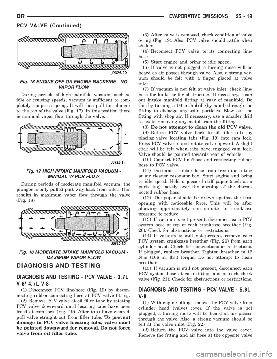
During periods of high manifold vacuum, such as
idle or cruising speeds, vacuum is sufficient to com-
pletely compress spring. It will then pull the plunger
to the top of the valve (Fig. 17). In this position there
is minimal vapor flow through the valve.
During periods of moderate manifold vacuum, the
plunger is only pulled part way back from inlet. This
results in maximum vapor flow through the valve
(Fig. 18).
DIAGNOSIS AND TESTING
DIAGNOSIS AND TESTING - PCV VALVE - 3.7L
V-6/ 4.7L V-8
(1) Disconnect PCV line/hose (Fig. 19) by discon-
necting rubber connecting hose at PCV valve fitting.
(2) Remove PCV valve at oil filler tube by rotating
PCV valve downward until locating tabs have been
freed at cam lock (Fig. 19). After tabs have cleared,
pull valve straight out from filler tube.To prevent
damage to PCV valve locating tabs, valve must
be pointed downward for removal. Do not force
valve from oil filler tube.(3) After valve is removed, check condition of valve
o-ring (Fig. 19). Also, PCV valve should rattle when
shaken.
(4) Reconnect PCV valve to its connecting line/
hose.
(5) Start engine and bring to idle speed.
(6) If valve is not plugged, a hissing noise will be
heard as air passes through valve. Also, a strong vac-
uum should be felt with a finger placed at valve
inlet.
(7) If vacuum is not felt at valve inlet, check line/
hose for kinks or for obstruction. If necessary, clean
out intake manifold fitting at rear of manifold. Do
this by turning a 1/4 inch drill (by hand) through the
fitting to dislodge any solid particles. Blow out the
fitting with shop air. If necessary, use a smaller drill
to avoid removing any metal from the fitting.
(8)Do not attempt to clean the old PCV valve.
(9) Return PCV valve back to oil filler tube by
placing valve locating tabs (Fig. 19) into cam lock.
Press PCV valve in and rotate valve upward. A slight
click will be felt when tabs have engaged cam lock.
Valve should be pointed towards rear of vehicle.
(10) Connect PCV line/hose and connecting rubber
hose to PCV valve.
(11) Disconnect rubber hose from fresh air fitting
at air cleaner resonator box. Start engine and bring
to idle speed. Hold a piece of stiff paper (such as a
parts tag) loosely over the opening of the discon-
nected rubber hose.
(12) The paper should be drawn against the hose
opening with noticeable force. This will be after
allowing approximately one minute for crankcase
pressure to reduce.
(13) If vacuum is not present, disconnect each PCV
system hose at top of each crankcase breather (Fig.
20). Check for obstructions or restrictions.
(14) If vacuum is still not present, remove each
PCV system crankcase breather (Fig. 20) from each
cylinder head. Check for obstructions or restrictions.
If plugged, replace breather. Tighten breather to 12
N´m (106 in. lbs.) torque. Do not attempt to clean
breather.
(15) If vacuum is still not present, disconnect each
PCV system hose at each fitting, and at each check
valve (Fig. 21). Check for obstructions or restrictions.DIAGNOSIS AND TESTING - PCV VALVE - 5.9L
V-8
(1) With engine idling, remove the PCV valve from
cylinder head (valve) cover. If the valve is not
plugged, a hissing noise will be heard as air passes
through the valve. Also, a strong vacuum should be
felt at the valve inlet (Fig. 22).
(2) Return the PCV valve into the valve cover.
Remove the fitting and air hose at the opposite valve
Fig. 16 ENGINE OFF OR ENGINE BACKFIRE - NO
VAPOR FLOW
Fig. 17 HIGH INTAKE MANIFOLD VACUUM -
MINIMAL VAPOR FLOW
Fig. 18 MODERATE INTAKE MANIFOLD VACUUM -
MAXIMUM VAPOR FLOW
DREVAPORATIVE EMISSIONS 25 - 19
PCV VALVE (Continued)
Page 2851 of 2895

tabs, valve must be pointed downward for
removal. Do not force valve from oil filler tube.
(3) After valve is removed, check condition of valve
o-ring (Fig. 25).
5.7L V-8
The PCV valve is mounted into the top of the
intake manifold, located to the right / rear of the
throttle body (Fig. 12). The PCV valve is sealed to
the intake manifold with 2 o-rings (Fig. 13).
(1) Remove PCV valve by rotating counter-clock-
wise 90 degrees until locating tabs have been freed.
After tabs have cleared, pull valve straight up from
intake manifold.
(2) After valve is removed, check condition of 2
valve o-rings.
INSTALLATION
3.7L V6 / 4.7L V-8
The PCV valve is located on the oil filler tube. Two
locating tabs are located on the side of the valve.
These 2 tabs fit into a cam lock in the oil filler tube.
An o-ring seals the valve to the filler tube.
(1) Return PCV valve back to oil filler tube by
placing valve locating tabs into cam lock. Press PCV
valve in and rotate valve upward. A slight click will
be felt when tabs have engaged cam lock. Valve
should be pointed towards rear of vehicle.
(2) Connect PCV line/hose and rubber hose to PCV
valve.
5.7L V-8
(1) Clean out intake manifold opening.
(2) Check condition of 2 o-rings on PCV valve.
(3) Apply engine oil to 2 o-rings.
(4) Place PCV valve into intake manifold and
rotate 90 degrees clockwise for installation.
VACUUM LINES
DESCRIPTION
A vacuum schematic for emission related items can
be found on the vehicles VECI label. Refer to Vehicle
Emission Control Information (VECI) Label for label
location.
VAPOR CANISTER
DESCRIPTION
Two, maintenance free, EVAP canisters are used.
Both canisters are mounted into a two-piece support
bracket located near the front of the fuel tank (Fig.
26).
OPERATION
Two, maintenance free, EVAP canisters are
used.The EVAP canisters are filled with granules of
an activated carbon mixture. Fuel vapors entering
the EVAP canisters are absorbed by the charcoal
granules.
Fuel tank pressure vents into the EVAP canisters.
Fuel vapors are temporarily held in the canisters
until they can be drawn into the intake manifold.
The duty cycle EVAP canister purge solenoid allows
the EVAP canisters to be purged at predetermined
times and at certain engine operating conditions.
REMOVAL
Two, maintenance free, EVAP canisters are used.
Both canisters are mounted into a two-piece support
bracket located near the front of the fuel tank (Fig.
26).
(1) Raise and support vehicle.
(2) Remove fuel tubes/lines at each EVAP canister.
Note location of tubes/lines before removal for easier
installation.
(3) Remove lower support bracket (Fig. 27).
(4) Remove mounting nuts at top of each canister
(Fig. 27).
Fig. 26 LOCATION, EVAP CANISTERS
1 - LDP
2 - LDP MOUNTING BOLT
3 - ELEC. CONNEC.
4 - FILTER MOUNTING BOLT
5 - LDP FILTER
6 - CONNECTING HOSE
7 - EVAP CANISTER MOUNTING BRACKET
8 - EVAP CANISTERS (2)
25 - 22 EVAPORATIVE EMISSIONSDR
PCV VALVE (Continued)
Page 2862 of 2895
CHECKING ENGINE OIL PRESSURE -
DIAGNOSIS AND TESTING....9-150,9-214,9-64
CHECKING TRANSMISSION CLUTCH
OPERATION - DIAGNOSIS AND
TESTING, AIR......................21-494
CHECKS - DIAGNOSIS AND TESTING,
PRELIMINARY........................7-10
CHILD RESTRAINT ANCHOR -
DESCRIPTION.......................8O-14
CHILD RESTRAINT ANCHOR -
INSTALLATION......................8O-17
CHILD RESTRAINT ANCHOR -
OPERATION.........................8O-16
CHILD RESTRAINT ANCHOR - REMOVAL . . 8O-16
CHIME CONDITIONS - DIAGNOSIS AND
TESTING............................8B-2
CHIME/BUZZER - DESCRIPTION..........8B-1
CHIME/BUZZER - OPERATION............8B-1
CIGAR LIGHTER OUTLET - DESCRIPTION . 8W-97-2
CIGAR LIGHTER OUTLET - DIAGNOSIS
AND TESTING.....................8W-97-2
CIGAR LIGHTER OUTLET - OPERATION . 8W-97-2
CIRCUIT - DIAGNOSIS AND TESTING,
AMBIENT TEMPERATURE SENSOR......8M-11
CIRCUIT - OPERATION, FUEL DRAIN.....14-78
CIRCUIT ACTUATION TEST MODE -
DESCRIPTION........................25-1
CIRCUIT FUNCTIONS - DESCRIPTION . . 8W-01-6
CIRCUIT INFORMATION - DESCRIPTION . 8W-01-5
CIRCUIT SENSE - DESCRIPTION,
IGNITION...........................8E-10
CIRCUIT SENSE - OPERATION, IGNITION . . 8E-12
CIRCUITS - OPERATION, NON-
MONITORED.........................25-8
CLAMPS - DESCRIPTION, HOSE...........7-3
CLAMPS - OPERATION, HOSE.............7-5
CLEANING/REVERSE FLUSHING -
STANDARD PROCEDURE, COOLING
SYSTEM............................7-17
CLEARANCE - STANDARD PROCEDURE,
CONNECTING ROD BEARING AND
CRANKSHAFT JOURNAL...............9-321
CLEARANCE - STANDARD PROCEDURE,
MAIN BEARING......................9-322
CLEARANCE LAMP - INSTALLATION, CAB . 8L-10
CLEARANCE LAMP - REMOVAL, CAB.....8L-10
CLOCKSPRING - DESCRIPTION.........8O-18
CLOCKSPRING - INSTALLATION.........8O-21
CLOCKSPRING - OPERATION...........8O-18
CLOCKSPRING - REMOVAL............8O-20
CLOCKSPRING CENTERING - STANDARD
PROCEDURE........................8O-19
CLUSTER - ASSEMBLY, INSTRUMENT....8J-15
CLUSTER - DESCRIPTION, INSTRUMENT . . . 8J-2
CLUSTER - DIAGNOSIS AND TESTING,
INSTRUMENT........................8J-10
CLUSTER - DISASSEMBLY, INSTRUMENT . . 8J-14
CLUSTER - INSTALLATION, INSTRUMENT . 8J-16
CLUSTER - OPERATION, INSTRUMENT.....8J-6
CLUSTER - REMOVAL, INSTRUMENT.....8J-14
CLUSTER BEZEL - INSTALLATION........23-50
CLUSTER BEZEL - REMOVAL...........23-50
CLUTCH - 5.9L DIESEL - DESCRIPTION,
FAN DRIVE VISCOUS...................7-55
CLUTCH - 5.9L DIESEL - OPERATION,
FAN DRIVE VISCOUS...................7-55
CLUTCH - ASSEMBLY, FRONT....21-206,21-386
CLUTCH - ASSEMBLY, LOW/REVERSE . . . 21-561
CLUTCH - ASSEMBLY, REAR.....21-250,21-428
CLUTCH - CLEANING, LOW/REVERSE....21-561
CLUTCH - CLEANING, REAR.....21-250,21-428
CLUTCH - DESCRIPTION.................6-1
CLUTCH - DESCRIPTION, A/C
COMPRESSOR........................24-9
CLUTCH - DESCRIPTION, FAN DRIVE
VISCOUS............................7-54
CLUTCH - DESCRIPTION, FRONT . 21-204,21-384
CLUTCH - DESCRIPTION, OVERDRIVE . . . 21-218,
21-396
CLUTCH - DESCRIPTION, REAR . . 21-248,21-426
CLUTCH - DIAGNOSIS AND TESTING.......6-2
CLUTCH - DISASSEMBLY, FRONT . 21-205,21-384
CLUTCH - DISASSEMBLY, LOW/REVERSE
. 21-560
CLUTCH - DISASSEMBLY, REAR
. . 21-249,21-427
CLUTCH - INSPECTION, A/C
COMPRESSOR
.......................24-12
CLUTCH - INSPECTION, FRONT
. . 21-206,21-385
CLUTCH - INSPECTION, LOW/REVERSE
. . 21-561CLUTCH - INSPECTION, REAR . . . 21-250,21-428
CLUTCH - INSTALLATION, A/C
COMPRESSOR.......................24-12
CLUTCH - OPERATION..................6-1
CLUTCH - OPERATION, A/C
COMPRESSOR........................24-9
CLUTCH - OPERATION, FAN DRIVE
VISCOUS............................7-54
CLUTCH - OPERATION, FRONT . . . 21-204,21-384
CLUTCH - OPERATION, OVERDRIVE....21-218,
21-396
CLUTCH - OPERATION, REAR....21-249,21-427
CLUTCH - REMOVAL, A/C COMPRESSOR . . 24-10
CLUTCH - SPECIFICATIONS...............6-6
CLUTCH - WARNING....................6-2
CLUTCH AND BAND OPERATION -
DIAGNOSIS AND TESTING, AIR
TESTING TRANSMISSION.......21-143,21-324
CLUTCH ASSEMBLY - ASSEMBLY, INPUT . 21-552
CLUTCH ASSEMBLY - DESCRIPTION,
INPUT............................21-549
CLUTCH ASSEMBLY - DISASSEMBLY,
INPUT............................21-550
CLUTCH ASSEMBLY - OPERATION,
INPUT............................21-549
CLUTCH BREAK-IN - STANDARD
PROCEDURE, A/C COMPRESSOR........24-10
CLUTCH CAM/OVERDRIVE PISTON
RETAINER - ASSEMBLY,
OVERRUNNING...............21-239,21-416
CLUTCH CAM/OVERDRIVE PISTON
RETAINER - CLEANING, OVERRUNNING. . . 21-238,
21-416
CLUTCH CAM/OVERDRIVE PISTON
RETAINER - DESCRIPTION,
OVERRUNNING...............21-237,21-415
CLUTCH CAM/OVERDRIVE PISTON
RETAINER - DISASSEMBLY,
OVERRUNNING...............21-238,21-415
CLUTCH CAM/OVERDRIVE PISTON
RETAINER - INSPECTION,
OVERRUNNING...............21-238,21-416
CLUTCH CAM/OVERDRIVE PISTON
RETAINER - OPERATION,
OVERRUNNING...............21-237,21-415
CLUTCH COIL - DIAGNOSIS AND
TESTING, A/C COMPRESSOR...........24-10
CLUTCH DISC - INSTALLATION............6-6
CLUTCH DISC - REMOVAL...............6-6
CLUTCH HOUSING - DIAGNOSIS AND
TESTING.............................6-8
CLUTCH HOUSING - INSTALLATION.......6-10
CLUTCH HOUSING - REMOVAL...........6-10
CLUTCH OPERATION - DIAGNOSIS AND
TESTING, AIR CHECKING
TRANSMISSION.....................21-494
CLUTCH PEDAL POSITION SWITCH -
DESCRIPTION........................6-14
CLUTCH PEDAL POSITION SWITCH -
DIAGNOSIS AND TESTING..............6-14
CLUTCH PEDAL POSITION SWITCH -
OPERATION..........................6-14
CLUTCH RELAY - DESCRIPTION, A/C
COMPRESSOR.......................24-13
CLUTCH RELAY - DIAGNOSIS AND
TESTING, COMPRESSOR...............24-13
CLUTCH RELAY - INSTALLATION, A/C
COMPRESSOR.......................24-14
CLUTCH RELAY - OPERATION, A/C
COMPRESSOR.......................24-13
CLUTCH RELAY - REMOVAL, A/C
COMPRESSOR.......................24-14
CLUTCH RELEASE BEARING -
INSTALLATION........................6-11
CLUTCH RELEASE BEARING - REMOVAL . . . 6-11
CLUTCHES - DESCRIPTION, HOLDING . . . 21-546
CLUTCHES - OPERATION, HOLDING.....21-546
COAT HOOK - INSTALLATION...........23-67
COAT HOOK - REMOVAL...............23-67
CODE - DESCRIPTION, PAINT...........23-74
CODE PLATE - DESCRIPTION, BODY
....Intro.-4
CODES - DESCRIPTION, DIAGNOSTIC
TROUBLE
............................25-1
CODES - SPECIFICATIONS, PAINT
........23-74
CODES - STANDARD PROCEDURE,
ERASING TRANSMITTER
..............8M-12
CODES - STANDARD PROCEDURE,
SETTING TRANSMITTER
..............8M-12COIL - DESCRIPTION, IGNITION.........8I-19
COIL - DIAGNOSIS AND TESTING, A/C
COMPRESSOR CLUTCH...............24-10
COIL - INSTALLATION, IGNITION.........8I-24
COIL - OPERATION, IGNITION...........8I-20
COIL - REMOVAL, IGNITION............8I-23
COIL CAPACITOR - DESCRIPTION,
IGNITION...........................8I-33
COIL CAPACITOR - INSTALLATION,
IGNITION...........................8I-33
COIL CAPACITOR - OPERATION,
IGNITION...........................8I-33
COIL CAPACITOR - REMOVAL, IGNITION . . . 8I-33
COIL RESISTANCE, 3.7L V-6 - IGNITION....8I-6
COIL RESISTANCE, 4.7L V-8 - IGNITION....8I-6
COIL RESISTANCE, 5.7L V-8 - IGNITION....8I-6
COIL RESISTANCE, 5.9L - IGNITION.......8I-6
COIL RESISTANCE, 8.0L V-10 ENGINE -
IGNITION............................8I-6
COLUMN - DESCRIPTION...............19-6
COLUMN - DIAGNOSIS AND TESTING,
STEERING...........................19-7
COLUMN - INSTALLATION...............19-9
COLUMN - REMOVAL..................19-7
COLUMN OPENING COVER -
INSTALLATION, STEERING.............23-61
COLUMN OPENING COVER - REMOVAL,
STEERING..........................23-61
COLUMN OPENING SUPPORT BRACKET
- INSTALLATION, STEERING..............23-62
COLUMN OPENING SUPPORT BRACKET
- REMOVAL, STEERING................23-61
COMBUSTION PRESSURE LEAKAGE -
DIAGNOSIS AND TESTING, CYLINDER....9-182,
9-231,9-359,9-8,9-92
COMMUNICATION - DESCRIPTION........8E-1
COMMUNICATION - OPERATION..........8E-2
COMPASS CALIBRATION - STANDARD
PROCEDURE.........................8M-3
COMPASS DEMAGNETIZING -
STANDARD PROCEDURE...............8M-4
COMPASS MINI-TRIP COMPUTER -
DIAGNOSIS AND TESTING..............8M-7
COMPASS VARIATION ADJUSTMENT -
STANDARD PROCEDURE...............8M-4
COMPASS/MINI-TRIP COMPUTER -
DESCRIPTION........................8M-6
COMPASS/MINI-TRIP COMPUTER -
INSTALLATION.......................8M-7
COMPASS/MINI-TRIP COMPUTER -
OPERATION.........................8M-7
COMPASS/MINI-TRIP COMPUTER -
REMOVAL...........................8M-7
COMPRESSION PRESSURE - DIAGNOSIS
AND TESTING, CYLINDER . . . 9-182,9-231,9-359,
9-8,9-92
COMPRESSION/LEAKAGE TESTS -
DIAGNOSIS AND TESTING, CYLINDER....9-288
COMPRESSOR CLUTCH - DESCRIPTION,
A/C ................................24-9
COMPRESSOR CLUTCH - INSPECTION,
A/C................................24-12
COMPRESSOR CLUTCH - INSTALLATION,
A/C
................................24-12
COMPRESSOR CLUTCH - OPERATION,
A/C
................................24-9
COMPRESSOR CLUTCH - REMOVAL, A/C
. . 24-10
COMPRESSOR CLUTCH BREAK-IN -
STANDARD PROCEDURE, A/C
...........24-10
COMPRESSOR CLUTCH COIL -
DIAGNOSIS AND TESTING, A/C
..........24-10
COMPRESSOR CLUTCH RELAY -
DESCRIPTION, A/C
...................24-13
COMPRESSOR CLUTCH RELAY -
DIAGNOSIS AND TESTING
.............24-13
COMPRESSOR CLUTCH RELAY -
INSTALLATION, A/C
...................24-14
COMPRESSOR CLUTCH RELAY -
OPERATION, A/C
.....................24-13
COMPRESSOR CLUTCH RELAY -
REMOVAL, A/C
......................24-14
COMPRESSOR NOISE - DIAGNOSIS AND
TESTING, A/C
.......................24-36
COMPUTER - DESCRIPTION, COMPASS/
MINI-TRIP
..........................8M-6
COMPUTER - DIAGNOSIS AND TESTING,
COMPASS MINI-TRIP
..................8M-7
DRINDEX 7
Description Group-Page Description Group-Page Description Group-Page
Page 2867 of 2895
DROP - STANDARD PROCEDURE,
TESTING FOR A VOLTAGE...........8W-01-10
DRUM IN HAT BRAKE - CLEANING,
REAR...............................5-33
DRUM IN HAT BRAKE - INSPECTION,
REAR...............................5-33
DUAL REAR WHEEL INSTALLATION -
STANDARD PROCEDURE...............22-12
DUCTS - INSTALLATION, FLOOR
DISTRIBUTION.......................24-27
DUCTS - INSTALLATION, INSTRUMENT
PANEL.............................24-29
DUCTS - REMOVAL, FLOOR
DISTRIBUTION.......................24-27
DUCTS - REMOVAL, INSTRUMENT
PANEL.............................24-29
DUST BOOT - INSTALLATION,
EXTENSION HOUSING SEAL.....21-652,21-716
DUST BOOT - REMOVAL, EXTENSION
HOUSING SEAL...............21-652,21-716
DUTY FRONT FRAME RAIL TIP
REPLACEMENT - STANDARD
PROCEDURE, LIGHT...................13-4
ECM - DESCRIPTION...................8E-4
ECM - OPERATION....................8E-4
EFFECTS OF INCORRECT FLUID LEVEL -
DIAGNOSIS AND TESTING......21-201,21-381,
21-541
ELECTRICAL CONTROLS - DIAGNOSIS
AND TESTING, OVERDRIVE......21-219,21-397
ELECTRONIC GOVERNOR -
DESCRIPTION................21-196,21-376
ELECTRONIC GOVERNOR -
INSTALLATION.................21-199,21-379
ELECTRONIC GOVERNOR - OPERATION . 21-196,
21-377
ELECTRONIC GOVERNOR - REMOVAL . . . 21-198,
21-378
ELECTRONIC VARIABLE BRAKE
PROPORTIONING - DESCRIPTION........5-43
ELECTRONIC VARIABLE BRAKE
PROPORTIONING - OPERATION..........5-43
ELECTRONIC VEHICLE INFO CENTER -
DESCRIPTION........................8M-7
ELECTRONIC VEHICLE INFO CENTER -
INSTALLATION......................8M-10
ELECTRONIC VEHICLE INFO CENTER -
OPERATION.........................8M-8
ELECTRONIC VEHICLE INFO CENTER -
REMOVAL..........................8M-10
ELECTRONIC VEHICLE INFORMATION
CENTER - DIAGNOSIS AND TESTING......8M-8
ELECTRONIC VEHICLE INFORMATION
CENTER PROGRAMMING - STANDARD
PROCEDURE.........................8M-8
ELECTRONICLY CONTOLLED VISCOUS
FAN DRIVE - DIAGNOSIS AND TESTING....7-56
ELECTROSTATIC DISCHARGE (ESD)
SENSITIVE DEVICES - STANDARD
PROCEDURE......................8W-01-8
ELEMENT - DESCRIPTION, HEATED SEAT . . 8G-5
ELEMENT - DIAGNOSIS AND TESTING,
HEATED SEAT ........................8G-6
ELEMENT - INSTALLATION, AIR
CLEANER........9-105,9-20,9-242,9-298,9-370
ELEMENT - INSTALLATION, HEATED
SEAT ...............................8G-6
ELEMENT - OPERATION, HEATED SEAT....8G-6
ELEMENT - REMOVAL, AIR CLEANER....9-105,
9-20,9-242,9-297,9-370
ELEMENT - REMOVAL, HEATED SEAT.....8G-6
EMISSION CONTROL INFORMATION
(VECI) - DESCRIPTION, VEHICLE.......Intro.-3
END - DIAGNOSIS AND TESTING, OUTER
TIE ROD............................19-31
END - INSTALLATION, OUTER TIE ROD . . . 19-32
END - INSTALLATION, TIE ROD.........19-37
END - REMOVAL, OUTER TIE ROD.......19-31
END - REMOVAL, TIE ROD.............19-36
ENGINE - 3.7L - DESCRIPTION............9-3
ENGINE - 5.7L - DESCRIPTION
..........9-178
ENGINE - 5.9L - DESCRIPTION
..........9-224
ENGINE - DESCRIPTION, COOLING
SYSTEM FLOW - 5.9L
...................7-1
ENGINE - DESCRIPTION, COOLING
SYSTEM FLOW 3.7L/4.7L
................7-1
ENGINE - DESCRIPTION, FUEL
REQUIREMENTS - DIESEL
...............0-1ENGINE - DIAGNOSIS AND TESTING,
COOLING SYSTEM DIESEL...............7-7
ENGINE - DIAGNOSIS AND TESTING,
DIESEL.............................11-3
ENGINE - DIAGNOSIS AND TESTING,
GAS................................11-2
ENGINE - FIRING ORDER / CABLE
ROUTING, 5.7L V-8....................8I-4
ENGINE - IGNITION COIL RESISTANCE,
8.0L V-10............................8I-6
ENGINE - INSTALLATION...............9-291
ENGINE - INSTALLATION, 5.9L DIESEL . . . 24-39,
24-42,24-44
ENGINE - INSTALLATION, 8.0L..........24-42
ENGINE - INSTALLATION, EXCEPT V-10
OR DIESEL.........................8R-17
ENGINE - INSTALLATION, GAS..........19-24
ENGINE - INSTALLATION, V-10 OR
DIESEL............................8R-17
ENGINE - REMOVAL..................9-290
ENGINE - REMOVAL, 5.9L DIESEL . . 24-37,24-40,
24-43,24-46
ENGINE - REMOVAL, 8.0L..............24-40
ENGINE - REMOVAL, EXCEPT V-10 OR
DIESEL............................8R-16
ENGINE - REMOVAL, GAS..............19-23
ENGINE - REMOVAL, V-10 OR DIESEL....8R-16
ENGINE - SPARK PLUG CABLE ORDER,
8.0L V-10............................8I-5
ENGINE - SPECIFICATIONS, 3.7L.........9-12
ENGINE - STANDARD PROCEDURE,
DRAINING COOLING SYSTEM
3.7L/4.7L/5.7L........................7-18
ENGINE - STANDARD PROCEDURE,
DRAINING COOLING SYSTEM 5.9L
DIESEL.............................7-19
ENGINE - STANDARD PROCEDURE,
DRAINING COOLING SYSTEM
5.9L/8.0L............................7-18
ENGINE - STANDARD PROCEDURE,
REFILLING COOLING SYSTEM
3.7L/4.7L/5.7L........................7-18
ENGINE - STANDARD PROCEDURE,
REFILLING COOLING SYSTEM 5.9L
DIESEL.............................7-19
ENGINE - STANDARD PROCEDURE,
REFILLING COOLING SYSTEM
5.9L/8.0L............................7-18
ENGINE 5.9L DIESEL - DESCRIPTION.....9-282
ENGINE 8.0L - DESCRIPTION...........9-353
ENGINE BLOCK - CLEANING . 9-127,9-200,9-249,
9-38,9-380
ENGINE BLOCK - DESCRIPTION.....9-126,9-37
ENGINE BLOCK - INSPECTION.....9-127,9-200,
9-249,9-38,9-380
ENGINE BLOCK HEATER - 5.9L DIESEL -
DESCRIPTION........................7-43
ENGINE BLOCK HEATER - 5.9L DIESEL -
INSTALLATION........................7-44
ENGINE BLOCK HEATER - 5.9L DIESEL -
OPERATION..........................7-43
ENGINE BLOCK HEATER - 5.9L DIESEL -
REMOVAL...........................7-43
ENGINE BLOCK HEATER - DESCRIPTION . . . 7-42
ENGINE BLOCK HEATER - DIAGNOSIS
AND TESTING........................7-42
ENGINE BLOCK HEATER - INSTALLATION . . . 7-43
ENGINE BLOCK HEATER - OPERATION.....7-42
ENGINE BLOCK HEATER - REMOVAL......7-43
ENGINE CONTROL MODULE -
INSTALLATION........................8E-5
ENGINE CONTROL MODULE - REMOVAL . . . 8E-4
ENGINE COOLANT - DESCRIPTION........7-36
ENGINE COOLANT - DESCRIPTION.........0-3
ENGINE COOLANT TEMPERATURE
SENSOR - DESCRIPTION...............7-44
ENGINE COOLANT TEMPERATURE
SENSOR - INSTALLATION...............7-47
ENGINE COOLANT TEMPERATURE
SENSOR - OPERATION
.................7-44
ENGINE COOLANT TEMPERATURE
SENSOR - REMOVAL
...................7-44
ENGINE COOLANT THERMOSTAT -
3.7L/4.7L - DESCRIPTION
...............7-50
ENGINE COOLANT THERMOSTAT -
3.7L/4.7L - INSTALLATION
..............7-51
ENGINE COOLANT THERMOSTAT -
3.7L/4.7L - OPERATION
.................7-51ENGINE COOLANT THERMOSTAT -
3.7L/4.7L - REMOVAL..................7-51
ENGINE COOLANT THERMOSTAT - 5.9L
DIESEL - DESCRIPTION................7-52
ENGINE COOLANT THERMOSTAT - 5.9L
DIESEL - INSTALLATION................7-53
ENGINE COOLANT THERMOSTAT - 5.9L
DIESEL - OPERATION..................7-52
ENGINE COOLANT THERMOSTAT - 5.9L
DIESEL - REMOVAL....................7-53
ENGINE COOLANT THERMOSTAT-
5.7L/5.9L - DESCRIPTION...............7-47
ENGINE COOLANT THERMOSTAT-
5.7L/5.9L - INSTALLATION..............7-49
ENGINE COOLANT THERMOSTAT-
5.7L/5.9L - OPERATION.................7-48
ENGINE COOLANT THERMOSTAT-
5.7L/5.9L - REMOVAL..................7-48
ENGINE DATA PLATE - DESCRIPTION.....9-297
ENGINE DIAGNOSIS - INTRODUCTION -
DIAGNOSIS AND TESTING . . . 9-178,9-225,9-353,
9-4,9-93
ENGINE DIAGNOSIS - LUBRICATION -
DIAGNOSIS AND TESTING . . . 9-183,9-230,9-358,
9-7
ENGINE DIAGNOSIS - MECHANICAL -
DIAGNOSIS AND TESTING . . . 9-181,9-184,9-228,
9-283,9-356,9-6,9-91
ENGINE DIAGNOSIS - PERFORMANCE -
DIAGNOSIS AND TESTING . . . 9-179,9-226,9-354,
9-4,9-89
ENGINE FIRING ORDER, 3.7L V-6.........8I-4
ENGINE FIRING ORDER, 4.7L V-8.........8I-4
ENGINE FIRING ORDER, 5.9L V-8...........8I-4
ENGINE GASKET SURFACE
PREPARATION - STANDARD
PROCEDURE.........................9-10
ENGINE OIL - STANDARD PROCEDURE . . . 9-269,
9-396
ENGINE OIL AND LUBRICANTS -
DESCRIPTION.........................0-2
ENGINE OIL LEAK - DIAGNOSIS AND
TESTING..................9-150,9-214,9-63
ENGINE OIL LEAKS - DIAGNOSIS AND
TESTING......................9-269,9-394
ENGINE OIL LEVEL - STANDARD
PROCEDURE........................9-341
ENGINE OIL PRESSURE - DIAGNOSIS
AND TESTING.............9-269,9-338,9-396
ENGINE OIL PRESSURE - DIAGNOSIS
AND TESTING, CHECKING.....9-150,9-214,9-64
ENGINE OIL SERVICE - STANDARD
PROCEDURE..........9-151,9-215,9-341,9-70
ENGINE, SPECIAL TOOLS - 4.7L.........9-102
ENGINE, SPECIAL TOOLS - 5.7L.........9-192
ENGINE, SPECIAL TOOLS - 5.9L.........9-240
ENGINE, SPECIAL TOOLS - 5.9L DIESEL . . 9-294
ENGINE, SPECIAL TOOLS - 8.0L.........9-367
ENGINE, SPECIFICATIONS - 4.7L.........9-98
ENGINE, SPECIFICATIONS - 5.7L........9-188
ENGINE, SPECIFICATIONS - 5.9L........9-235
ENGINE, SPECIFICATIONS - 8.OL........9-364
ENGINE TEMPERATURE GAUGE -
DESCRIPTION
.......................8J-23
ENGINE TEMPERATURE GAUGE -
OPERATION
.........................8J-23
ENGINE TIMING - VERIFICATION -
STANDARD PROCEDURE
...............9-165
ENGINES - INSTALLATION, 3.7, 4.7 AND
5.7L
...............................24-41
ENGINES - REMOVAL, 3.7, 4.7 AND 5.7L
. . 24-39
ENTRY MODULE - DESCRIPTION,
REMOTE KEYLESS
....................8N-7
ENTRY MODULE - DIAGNOSIS AND
TESTING, REMOTE KEYLESS
............8N-8
ENTRY MODULE - INSTALLATION,
REMOTE KEYLESS
....................8N-8
ENTRY MODULE - OPERATION, REMOTE
KEYLESS
............................8N-8
ENTRY MODULE - REMOVAL, REMOTE
KEYLESS
............................8N-8
ENTRY TRANSMITTER - DIAGNOSIS AND
TESTING, REMOTE KEYLESS
............8N-8
ENTRY TRANSMITTER -
SPECIFICATIONS, REMOTE KEYLESS
.....8N-10
EQUIPMENT - STANDARD PROCEDURE,
REFRIGERANT SYSTEM SERVICE
........24-34
12 INDEXDR
Description Group-Page Description Group-Page Description Group-Page