2003 DODGE RAM light
[x] Cancel search: lightPage 2649 of 2895
PAINT
TABLE OF CONTENTS
page page
PAINT
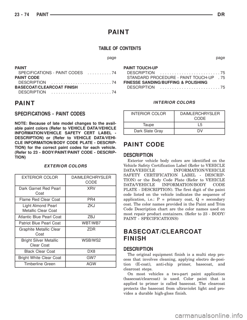
SPECIFICATIONS - PAINT CODES..........74
PAINT CODE
DESCRIPTION.........................74
BASECOAT/CLEARCOAT FINISH
DESCRIPTION.........................74PAINT TOUCH-UP
DESCRIPTION.........................75
STANDARD PROCEDURE - PAINT TOUCH-UP . 75
FINESSE SANDING/BUFFING & POLISHING
DESCRIPTION.........................75
PAINT
SPECIFICATIONS - PAINT CODES
NOTE: Because of late model changes to the avail-
able paint colors (Refer to VEHICLE DATA/VEHICLE
INFORMATION/VEHICLE SAFETY CERT LABEL -
DESCRIPTION) or (Refer to VEHICLE DATA/VEHI-
CLE INFORMATION/BODY CODE PLATE - DESCRIP-
TION) for the correct paint codes for each vehicle.
(Refer to 23 - BODY/PAINT/PAINT CODE - DESCRIP-
TION)
EXTERIOR COLORS
EXTERIOR COLOR DAIMLERCHRYSLER
CODE
Dark Garnet Red Pearl
CoatXRV
Flame Red Clear Coat PR4
Light Almond Pearl
Metallic Clear CoatZKJ
Atlantic Blue Pearl Coat ZBJ
Patriot Blue Pearl Coat WBT/WB7
Graphite Metallic Clear
CoatZDR
Bright Silver Metallic
Clear CoatWSB/WS2
Black Clear Coat DX8
Bright White Clear Coat GW7
Timberline Green AGW
INTERIOR COLORS
INTERIOR COLOR DAIMLERCHRYSLER
CODE
Taupe L5
Dark Slate Gray DV
PAINT CODE
DESCRIPTION
Exterior vehicle body colors are identified on the
Vehicle Safety Certification Label (Refer to VEHICLE
DATA/VEHICLE INFORMATION/VEHICLE
SAFETY CERTIFICATION LABEL - DESCRIP-
TION) or the Body Code Plate (Refer to VEHICLE
DATA/VEHICLE INFORMATION/BODY CODE
PLATE - DESCRIPTION). The first digit of the paint
code listed on the vehicle indicates the sequence of
application, i.e.: P = primary coat, Q = secondary
coat. The color names provided in the Paint and Trim
Code Description chart are the color names used on
most repair product containers. (Refer to 23 - BODY/
PAINT - SPECIFICATIONS)
BASECOAT/CLEARCOAT
FINISH
DESCRIPTION
The original equipment finish is a multi step pro-
cess that involves cleaning, applying electro de-posi-
tion (E-coat), anti-chip primer, basecoat, and
clearcoat steps.
On most vehicles a two-part paint application
(basecoat/clearcoat) is used. Color paint that is
applied to primer is called basecoat. The clearcoat
protects the basecoat from ultraviolet light and pro-
vides a durable high-gloss finish.
23 - 74 PAINTDR
Page 2650 of 2895
CAUTION: Do not use abrasive chemicals or com-
pounds on painted surfaces. Damage to finish can
result.
Do not use harsh alkaline based cleaning solvents
on painted surfaces. Damage to finish or color can
result.
PAINT TOUCH-UP
DESCRIPTION
When a painted metal surface has been scratched
or chipped, it should be touched-up as soon as possi-
ble to avoid corrosion. For best results, use MOPARt
Scratch Filler/Primer, Touch-Up Paints and Clear Top
Coat. (Refer to VEHICLE DATA/VEHICLE INFOR-
MATION/BODY CODE PLATE - DESCRIPTION) for
Body Code Plate information.
WARNING: USE AN OSHA APPROVED RESPIRATOR
AND SAFETY GLASSES WHEN SPRAYING PAINT
OR SOLVENTS IN A CONFINED AREA. PERSONAL
INJURY CAN RESULT.
STANDARD PROCEDURE - PAINT TOUCH-UP
(1) Scrape loose paint and corrosion from inside
scratch or chip.
(2) Clean affected area with MOPARtTar/Road
Oil Remover or equivalent, and allow to dry.
(3) Fill the inside of the scratch or chip with a coat
of filler/primer. Do not overlap primer onto good sur-
face finish. The applicator brush should be wet
enough to puddle-fill the scratch or chip without run-
ning. Do not stroke brush applicator on body surface.
Allow the filler/primer to dry hard.
(4) Cover the filler/primer with color touch-up
paint. Do not overlap touch-up color onto the original
color coat around the scratch or chip. Butt the newcolor to the original color, if possible. Do not stroke
applicator brush on body surface. Allow touch-up
paint to dry hard.
(5) On vehicles without clearcoat, the touch-up
color can be lightly finesse sanded (1500 grit) and
polished with rubbing compound.
(6) On vehicles with clearcoat, apply clear top coat
to touch-up paint with the same technique as
described in Step 4. Allow clear top coat to dry hard.
If desired, Step 5 can be performed on clear top coat.
WARNING: AVOID PROLONGED SKIN CONTACT
WITH PETROLEUM OR ALCOHOL ± BASED CLEAN-
ING SOLVENTS. PERSONAL INJURY CAN RESULT.
AVOID PROLONGED SKIN CONTACT WITH PETRO-
LEUM OR ALCOHOL ± BASED CLEANING SOL-
VENTS. PERSONAL INJURY CAN RESULT.
FINESSE SANDING/BUFFING &
POLISHING
DESCRIPTION
CAUTION: Do not remove more than .5 mils of
clearcoat finish, if equipped. Basecoat paint must
retain clearcoat for durability.
Use a Paint Thickness Gauge #PR-ETG-2X or equiv-
alent to determine film thickness before and after
the repair.
Minor acid etching, orange peel, or smudging in
clearcoat or single-stage finishes can be reduced with
light finesse sanding, hand buffing, and polishing.If
the finish has been finesse sanded in the past,
it cannot be repeated. Finesse sanding opera-
tion should be performed by a trained automo-
tive paint technician.
DRPAINT 23 - 75
BASECOAT/CLEARCOAT FINISH (Continued)
Page 2664 of 2895
(4) Apply clear glass primer 25 mm (1 in.) wide
around perimeter of windshield and wipe with a new
clean and dry lint- free cloth.
(5) Apply black-out primer onto the glass using the
windshield molding as a guide. The primer should be
15 mm (5/8 in.) wide on the top and sides of the glass
and 25 mm (1 in.) on the bottom of windshield. Allow
at least three minutes drying time.
(6) Locatenewsupport spacers on support brack-
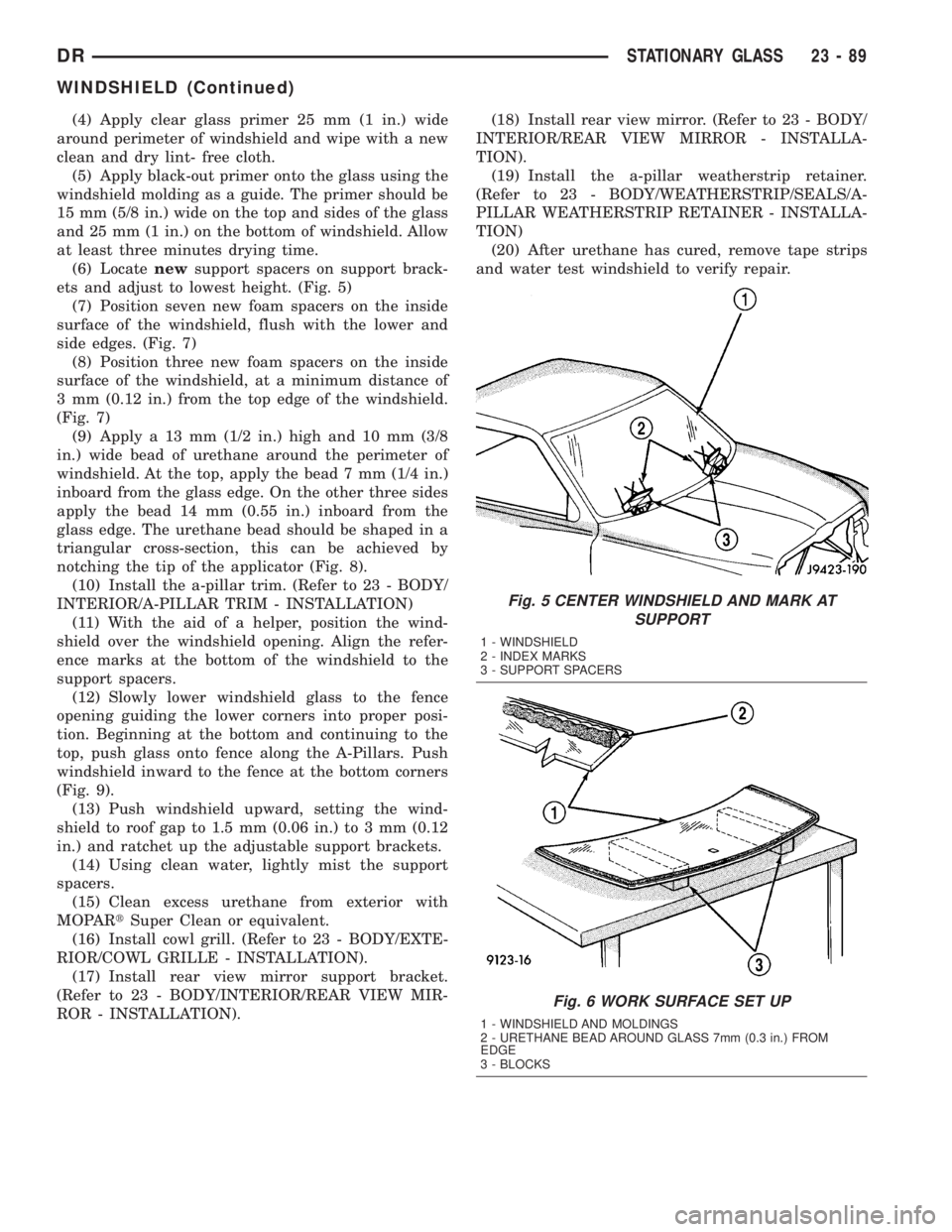
ets and adjust to lowest height. (Fig. 5)
(7) Position seven new foam spacers on the inside
surface of the windshield, flush with the lower and
side edges. (Fig. 7)
(8) Position three new foam spacers on the inside
surface of the windshield, at a minimum distance of
3 mm (0.12 in.) from the top edge of the windshield.
(Fig. 7)
(9) Apply a 13 mm (1/2 in.) high and 10 mm (3/8
in.) wide bead of urethane around the perimeter of
windshield. At the top, apply the bead 7 mm (1/4 in.)
inboard from the glass edge. On the other three sides
apply the bead 14 mm (0.55 in.) inboard from the
glass edge. The urethane bead should be shaped in a
triangular cross-section, this can be achieved by
notching the tip of the applicator (Fig. 8).
(10) Install the a-pillar trim. (Refer to 23 - BODY/
INTERIOR/A-PILLAR TRIM - INSTALLATION)
(11) With the aid of a helper, position the wind-
shield over the windshield opening. Align the refer-
ence marks at the bottom of the windshield to the
support spacers.
(12) Slowly lower windshield glass to the fence
opening guiding the lower corners into proper posi-
tion. Beginning at the bottom and continuing to the
top, push glass onto fence along the A-Pillars. Push
windshield inward to the fence at the bottom corners
(Fig. 9).
(13) Push windshield upward, setting the wind-
shield to roof gap to 1.5 mm (0.06 in.) to 3 mm (0.12
in.) and ratchet up the adjustable support brackets.
(14) Using clean water, lightly mist the support
spacers.
(15) Clean excess urethane from exterior with
MOPARtSuper Clean or equivalent.
(16) Install cowl grill. (Refer to 23 - BODY/EXTE-
RIOR/COWL GRILLE - INSTALLATION).
(17) Install rear view mirror support bracket.
(Refer to 23 - BODY/INTERIOR/REAR VIEW MIR-
ROR - INSTALLATION).(18) Install rear view mirror. (Refer to 23 - BODY/
INTERIOR/REAR VIEW MIRROR - INSTALLA-
TION).
(19) Install the a-pillar weatherstrip retainer.
(Refer to 23 - BODY/WEATHERSTRIP/SEALS/A-
PILLAR WEATHERSTRIP RETAINER - INSTALLA-
TION)
(20) After urethane has cured, remove tape strips
and water test windshield to verify repair.
Fig. 5 CENTER WINDSHIELD AND MARK AT
SUPPORT
1 - WINDSHIELD
2 - INDEX MARKS
3 - SUPPORT SPACERS
Fig. 6 WORK SURFACE SET UP
1 - WINDSHIELD AND MOLDINGS
2 - URETHANE BEAD AROUND GLASS 7mm (0.3 in.) FROM
EDGE
3 - BLOCKS
DRSTATIONARY GLASS 23 - 89
WINDSHIELD (Continued)
Page 2779 of 2895
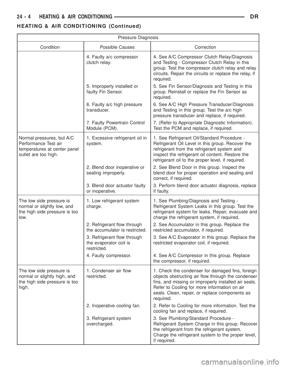
Pressure Diagnosis
Condition Possible Causes Correction
4. Faulty a/c compressor
clutch relay.4. See A/C Compressor Clutch Relay/Diagnosis
and Testing - Compressor Clutch Relay in this
group. Test the compressor clutch relay and relay
circuits. Repair the circuits or replace the relay, if
required.
5. Improperly installed or
faulty Fin Sensor.5. See Fin Sensor/Diagnosis and Testing in this
group. Reinstall or replace the Fin Sensor as
required.
6. Faulty a/c high pressure
transducer.6. See A/C High Pressure Transducer/Diagnosis
and Testing in this group. Test the a/c high
pressure transducer and replace, if required.
7. Faulty Powertrain Control
Module (PCM).7. (Refer to Appropriate Diagnostic Information).
Test the PCM and replace, if required.
Normal pressures, but A/C
Performance Test air
temperatures at center panel
outlet are too high.1. Excessive refrigerant oil in
system.1. See Refrigerant Oil/Standard Procedure -
Refrigerant Oil Level in this group. Recover the
refrigerant from the refrigerant system and
inspect the refrigerant oil content. Restore the
refrigerant oil to the proper level, if required.
2. Blend door inoperative or
sealing improperly.2. See Blend Door in this group. Inspect the
blend door for proper operation and sealing and
correct, if required.
3. Blend door actuator faulty
or inoperative.3. Perform blend door actuator diagnosis, replace
if faulty.
The low side pressure is
normal or slightly low, and
the high side pressure is too
low.1. Low refrigerant system
charge.1. See Plumbing/Diagnosis and Testing -
Refrigerant System Leaks in this group. Test the
refrigerant system for leaks. Repair, evacuate and
charge the refrigerant system, if required.
2. Refrigerant flow through
the accumulator is restricted.2. See Accumulator in this group. Replace the
restricted accumulator, if required.
3. Refrigerant flow through
the evaporator coil is
restricted.3. See A/C Evaporator in this group. Replace the
restricted evaporator coil, if required.
4. Faulty compressor. 4. See A/C Compressor in this group. Replace
the compressor, if required.
The low side pressure is
normal or slightly high, and
the high side pressure is too
high.1. Condenser air flow
restricted.1. Check the condenser for damaged fins, foreign
objects obstructing air flow through the condenser
fins, and missing or improperly installed air seals.
Refer to Cooling for more information on air
seals. Clean, repair, or replace components as
required.
2. Inoperative cooling fan. 2. Refer to Cooling for more information. Test the
cooling fan and replace, if required.
3. Refrigerant system
overcharged.3. See Plumbing/Standard Procedure -
Refrigerant System Charge in this group. Recover
the refrigerant from the refrigerant system.
Charge the refrigerant system to the proper level,
if required.
24 - 4 HEATING & AIR CONDITIONINGDR
HEATING & AIR CONDITIONING (Continued)
Page 2781 of 2895
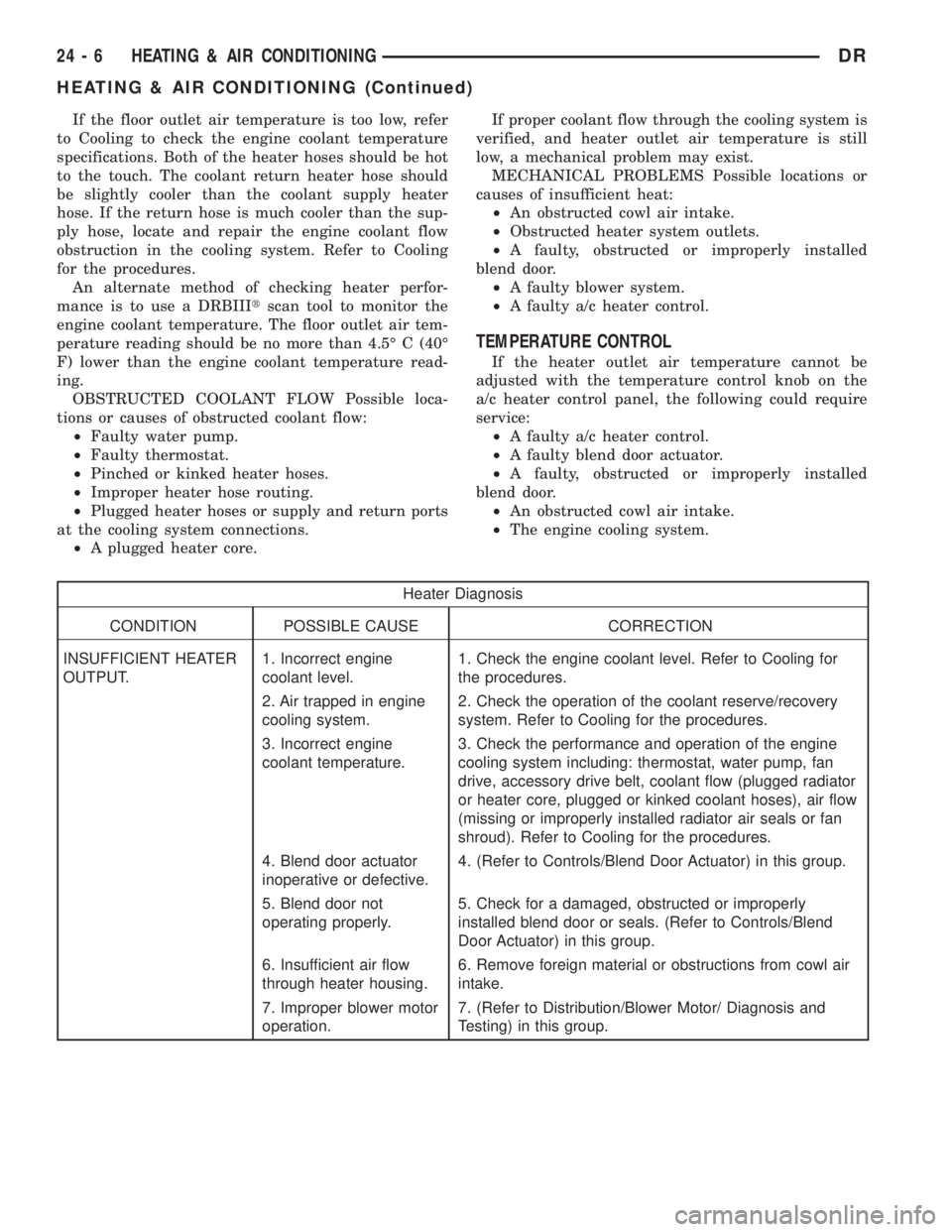
If the floor outlet air temperature is too low, refer
to Cooling to check the engine coolant temperature
specifications. Both of the heater hoses should be hot
to the touch. The coolant return heater hose should
be slightly cooler than the coolant supply heater
hose. If the return hose is much cooler than the sup-
ply hose, locate and repair the engine coolant flow
obstruction in the cooling system. Refer to Cooling
for the procedures.
An alternate method of checking heater perfor-
mance is to use a DRBIIItscan tool to monitor the
engine coolant temperature. The floor outlet air tem-
perature reading should be no more than 4.5É C (40É
F) lower than the engine coolant temperature read-
ing.
OBSTRUCTED COOLANT FLOW Possible loca-
tions or causes of obstructed coolant flow:
²Faulty water pump.
²Faulty thermostat.
²Pinched or kinked heater hoses.
²Improper heater hose routing.
²Plugged heater hoses or supply and return ports
at the cooling system connections.
²A plugged heater core.If proper coolant flow through the cooling system is
verified, and heater outlet air temperature is still
low, a mechanical problem may exist.
MECHANICAL PROBLEMS Possible locations or
causes of insufficient heat:
²An obstructed cowl air intake.
²Obstructed heater system outlets.
²A faulty, obstructed or improperly installed
blend door.
²A faulty blower system.
²A faulty a/c heater control.
TEMPERATURE CONTROL
If the heater outlet air temperature cannot be
adjusted with the temperature control knob on the
a/c heater control panel, the following could require
service:
²A faulty a/c heater control.
²A faulty blend door actuator.
²A faulty, obstructed or improperly installed
blend door.
²An obstructed cowl air intake.
²The engine cooling system.
Heater Diagnosis
CONDITION POSSIBLE CAUSE CORRECTION
INSUFFICIENT HEATER
OUTPUT.1. Incorrect engine
coolant level.1. Check the engine coolant level. Refer to Cooling for
the procedures.
2. Air trapped in engine
cooling system.2. Check the operation of the coolant reserve/recovery
system. Refer to Cooling for the procedures.
3. Incorrect engine
coolant temperature.3. Check the performance and operation of the engine
cooling system including: thermostat, water pump, fan
drive, accessory drive belt, coolant flow (plugged radiator
or heater core, plugged or kinked coolant hoses), air flow
(missing or improperly installed radiator air seals or fan
shroud). Refer to Cooling for the procedures.
4. Blend door actuator
inoperative or defective.4. (Refer to Controls/Blend Door Actuator) in this group.
5. Blend door not
operating properly.5. Check for a damaged, obstructed or improperly
installed blend door or seals. (Refer to Controls/Blend
Door Actuator) in this group.
6. Insufficient air flow
through heater housing.6. Remove foreign material or obstructions from cowl air
intake.
7. Improper blower motor
operation.7. (Refer to Distribution/Blower Motor/ Diagnosis and
Testing) in this group.
24 - 6 HEATING & AIR CONDITIONINGDR
HEATING & AIR CONDITIONING (Continued)
Page 2792 of 2895
trol module learns the blend air door stop positions
during the calibration procedure and will store a
Diagnostic Trouble Code (DTC) for any problems it
detects in the blend door actuator circuits. The blend
door actuator can be diagnosed using a DRBIIItscan
tool. Refer to the appropriate diagnostic information.
REMOVAL
The single zone heating and air conditioning sys-
tem is equipped with a single blend door actuator.
The dual zone system has two blend door actuators,
one for the driver side blend air door and one for the
passenger side blend air door. The same service pro-
cedures can be used for each of these actuators.
WARNING: ON VEHICLES EQUIPPED WITH AIR-
BAGS, DISABLE THE AIRBAG SYSTEM BEFORE
ATTEMPTING ANY STEERING WHEEL, STEERING
COLUMN, OR INSTRUMENT PANEL COMPONENT
DIAGNOSIS OR SERVICE. DISCONNECT AND ISO-
LATE THE BATTERY NEGATIVE (GROUND) CABLE,
THEN WAIT TWO MINUTES FOR THE AIRBAG SYS-
TEM CAPACITOR TO DISCHARGE BEFORE PER-
FORMING FURTHER DIAGNOSIS OR SERVICE. THIS
IS THE ONLY SURE WAY TO DISABLE THE AIRBAG
SYSTEM. FAILURE TO TAKE THE PROPER PRE-
CAUTIONS COULD RESULT IN ACCIDENTAL AIR-
BAG DEPLOYMENT AND POSSIBLE PERSONAL
INJURY.
(1) Disconnect and isolate the battery negative
cable.
(2) Remove the instrument panel assembly(Refer
to 23 - BODY/INSTRUMENT PANEL/INSTRUMENT
PANEL ASSEMBLY - REMOVAL).
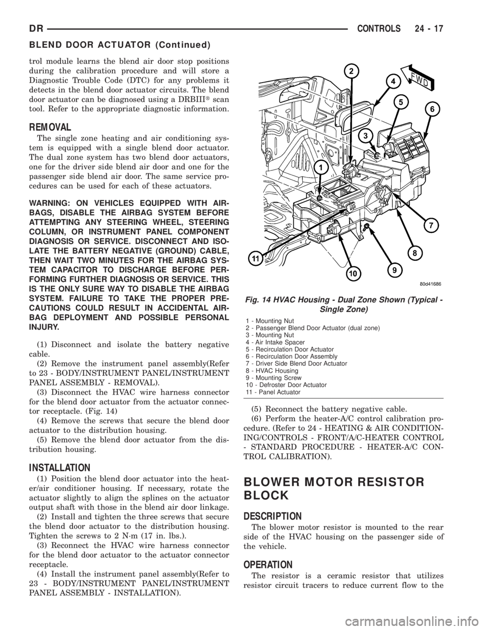
(3) Disconnect the HVAC wire harness connector
for the blend door actuator from the actuator connec-
tor receptacle. (Fig. 14)
(4) Remove the screws that secure the blend door
actuator to the distribution housing.
(5) Remove the blend door actuator from the dis-
tribution housing.
INSTALLATION
(1) Position the blend door actuator into the heat-
er/air conditioner housing. If necessary, rotate the
actuator slightly to align the splines on the actuator
output shaft with those in the blend air door linkage.
(2) Install and tighten the three screws that secure
the blend door actuator to the distribution housing.
Tighten the screws to 2 N´m (17 in. lbs.).
(3) Reconnect the HVAC wire harness connector
for the blend door actuator to the actuator connector
receptacle.
(4) Install the instrument panel assembly(Refer to
23 - BODY/INSTRUMENT PANEL/INSTRUMENT
PANEL ASSEMBLY - INSTALLATION).(5) Reconnect the battery negative cable.
(6) Perform the heater-A/C control calibration pro-
cedure. (Refer to 24 - HEATING & AIR CONDITION-
ING/CONTROLS - FRONT/A/C-HEATER CONTROL
- STANDARD PROCEDURE - HEATER-A/C CON-
TROL CALIBRATION).BLOWER MOTOR RESISTOR
BLOCK
DESCRIPTION
The blower motor resistor is mounted to the rear
side of the HVAC housing on the passenger side of
the vehicle.
OPERATION
The resistor is a ceramic resistor that utilizes
resistor circuit tracers to reduce current flow to the
Fig. 14 HVAC Housing - Dual Zone Shown (Typical -
Single Zone)
1 - Mounting Nut
2 - Passenger Blend Door Actuator (dual zone)
3 - Mounting Nut
4 - Air Intake Spacer
5 - Recirculation Door Actuator
6 - Recirculation Door Assembly
7 - Driver Side Blend Door Actuator
8 - HVAC Housing
9 - Mounting Screw
10 - Defroster Door Actuator
11 - Panel Actuator
DRCONTROLS 24 - 17
BLEND DOOR ACTUATOR (Continued)
Page 2797 of 2895
INSTALLATION
WARNING: ON VEHICLES EQUIPPED WITH AIR-
BAGS, DISABLE THE AIRBAG SYSTEM BEFORE
ATTEMPTING ANY STEERING WHEEL, STEERING
COLUMN, OR INSTRUMENT PANEL COMPONENT
DIAGNOSIS OR SERVICE. DISCONNECT AND ISO-
LATE THE BATTERY NEGATIVE (GROUND) CABLE,
THEN WAIT TWO MINUTES FOR THE AIRBAG SYS-
TEM CAPACITOR TO DISCHARGE BEFORE PER-
FORMING FURTHER DIAGNOSIS OR SERVICE. THIS
IS THE ONLY SURE WAY TO DISABLE THE AIRBAG
SYSTEM. FAILURE TO TAKE THE PROPER PRE-
CAUTIONS COULD RESULT IN ACCIDENTAL AIR-
BAG DEPLOYMENT AND POSSIBLE PERSONAL
INJURY.
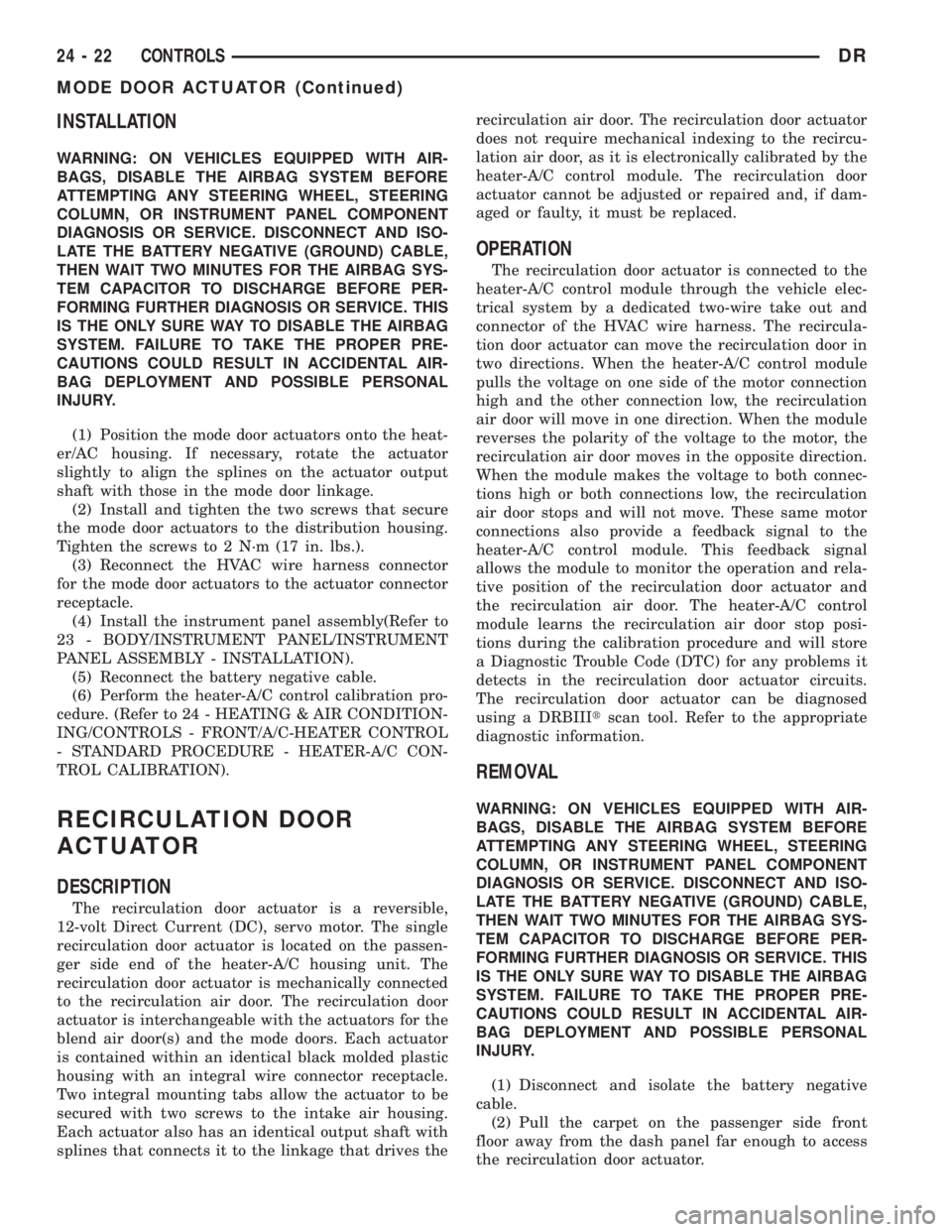
(1) Position the mode door actuators onto the heat-
er/AC housing. If necessary, rotate the actuator
slightly to align the splines on the actuator output
shaft with those in the mode door linkage.
(2) Install and tighten the two screws that secure
the mode door actuators to the distribution housing.
Tighten the screws to 2 N´m (17 in. lbs.).
(3) Reconnect the HVAC wire harness connector
for the mode door actuators to the actuator connector
receptacle.
(4) Install the instrument panel assembly(Refer to
23 - BODY/INSTRUMENT PANEL/INSTRUMENT
PANEL ASSEMBLY - INSTALLATION).
(5) Reconnect the battery negative cable.
(6) Perform the heater-A/C control calibration pro-
cedure. (Refer to 24 - HEATING & AIR CONDITION-
ING/CONTROLS - FRONT/A/C-HEATER CONTROL
- STANDARD PROCEDURE - HEATER-A/C CON-
TROL CALIBRATION).
RECIRCULATION DOOR
ACTUATOR
DESCRIPTION
The recirculation door actuator is a reversible,
12-volt Direct Current (DC), servo motor. The single
recirculation door actuator is located on the passen-
ger side end of the heater-A/C housing unit. The
recirculation door actuator is mechanically connected
to the recirculation air door. The recirculation door
actuator is interchangeable with the actuators for the
blend air door(s) and the mode doors. Each actuator
is contained within an identical black molded plastic
housing with an integral wire connector receptacle.
Two integral mounting tabs allow the actuator to be
secured with two screws to the intake air housing.
Each actuator also has an identical output shaft with
splines that connects it to the linkage that drives therecirculation air door. The recirculation door actuator
does not require mechanical indexing to the recircu-
lation air door, as it is electronically calibrated by the
heater-A/C control module. The recirculation door
actuator cannot be adjusted or repaired and, if dam-
aged or faulty, it must be replaced.
OPERATION
The recirculation door actuator is connected to the
heater-A/C control module through the vehicle elec-
trical system by a dedicated two-wire take out and
connector of the HVAC wire harness. The recircula-
tion door actuator can move the recirculation door in
two directions. When the heater-A/C control module
pulls the voltage on one side of the motor connection
high and the other connection low, the recirculation
air door will move in one direction. When the module
reverses the polarity of the voltage to the motor, the
recirculation air door moves in the opposite direction.
When the module makes the voltage to both connec-
tions high or both connections low, the recirculation
air door stops and will not move. These same motor
connections also provide a feedback signal to the
heater-A/C control module. This feedback signal
allows the module to monitor the operation and rela-
tive position of the recirculation door actuator and
the recirculation air door. The heater-A/C control
module learns the recirculation air door stop posi-
tions during the calibration procedure and will store
a Diagnostic Trouble Code (DTC) for any problems it
detects in the recirculation door actuator circuits.
The recirculation door actuator can be diagnosed
using a DRBIIItscan tool. Refer to the appropriate
diagnostic information.
REMOVAL
WARNING: ON VEHICLES EQUIPPED WITH AIR-
BAGS, DISABLE THE AIRBAG SYSTEM BEFORE
ATTEMPTING ANY STEERING WHEEL, STEERING
COLUMN, OR INSTRUMENT PANEL COMPONENT
DIAGNOSIS OR SERVICE. DISCONNECT AND ISO-
LATE THE BATTERY NEGATIVE (GROUND) CABLE,
THEN WAIT TWO MINUTES FOR THE AIRBAG SYS-
TEM CAPACITOR TO DISCHARGE BEFORE PER-
FORMING FURTHER DIAGNOSIS OR SERVICE. THIS
IS THE ONLY SURE WAY TO DISABLE THE AIRBAG
SYSTEM. FAILURE TO TAKE THE PROPER PRE-
CAUTIONS COULD RESULT IN ACCIDENTAL AIR-
BAG DEPLOYMENT AND POSSIBLE PERSONAL
INJURY.
(1) Disconnect and isolate the battery negative
cable.
(2) Pull the carpet on the passenger side front
floor away from the dash panel far enough to access
the recirculation door actuator.
24 - 22 CONTROLSDR
MODE DOOR ACTUATOR (Continued)
Page 2798 of 2895
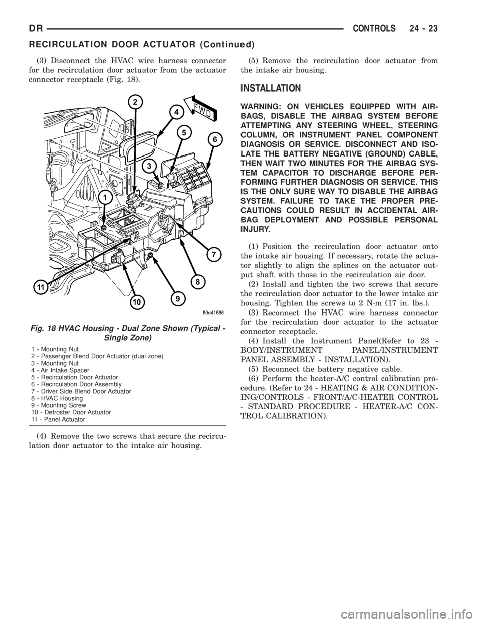
(3) Disconnect the HVAC wire harness connector
for the recirculation door actuator from the actuator
connector receptacle (Fig. 18).
(4) Remove the two screws that secure the recircu-
lation door actuator to the intake air housing.(5) Remove the recirculation door actuator from
the intake air housing.
INSTALLATION
WARNING: ON VEHICLES EQUIPPED WITH AIR-
BAGS, DISABLE THE AIRBAG SYSTEM BEFORE
ATTEMPTING ANY STEERING WHEEL, STEERING
COLUMN, OR INSTRUMENT PANEL COMPONENT
DIAGNOSIS OR SERVICE. DISCONNECT AND ISO-
LATE THE BATTERY NEGATIVE (GROUND) CABLE,
THEN WAIT TWO MINUTES FOR THE AIRBAG SYS-
TEM CAPACITOR TO DISCHARGE BEFORE PER-
FORMING FURTHER DIAGNOSIS OR SERVICE. THIS
IS THE ONLY SURE WAY TO DISABLE THE AIRBAG
SYSTEM. FAILURE TO TAKE THE PROPER PRE-
CAUTIONS COULD RESULT IN ACCIDENTAL AIR-
BAG DEPLOYMENT AND POSSIBLE PERSONAL
INJURY.
(1) Position the recirculation door actuator onto
the intake air housing. If necessary, rotate the actua-
tor slightly to align the splines on the actuator out-
put shaft with those in the recirculation air door.
(2) Install and tighten the two screws that secure
the recirculation door actuator to the lower intake air
housing. Tighten the screws to 2 N´m (17 in. lbs.).
(3) Reconnect the HVAC wire harness connector
for the recirculation door actuator to the actuator
connector receptacle.
(4) Install the Instrument Panel(Refer to 23 -
BODY/INSTRUMENT PANEL/INSTRUMENT
PANEL ASSEMBLY - INSTALLATION).
(5) Reconnect the battery negative cable.
(6) Perform the heater-A/C control calibration pro-
cedure. (Refer to 24 - HEATING & AIR CONDITION-
ING/CONTROLS - FRONT/A/C-HEATER CONTROL
- STANDARD PROCEDURE - HEATER-A/C CON-
TROL CALIBRATION).
Fig. 18 HVAC Housing - Dual Zone Shown (Typical -
Single Zone)
1 - Mounting Nut
2 - Passenger Blend Door Actuator (dual zone)
3 - Mounting Nut
4 - Air Intake Spacer
5 - Recirculation Door Actuator
6 - Recirculation Door Assembly
7 - Driver Side Blend Door Actuator
8 - HVAC Housing
9 - Mounting Screw
10 - Defroster Door Actuator
11 - Panel Actuator
DRCONTROLS 24 - 23
RECIRCULATION DOOR ACTUATOR (Continued)