2003 DODGE RAM light
[x] Cancel search: lightPage 1752 of 2895
(5) Install air duct/air box to throttle body.
5.9L V-8
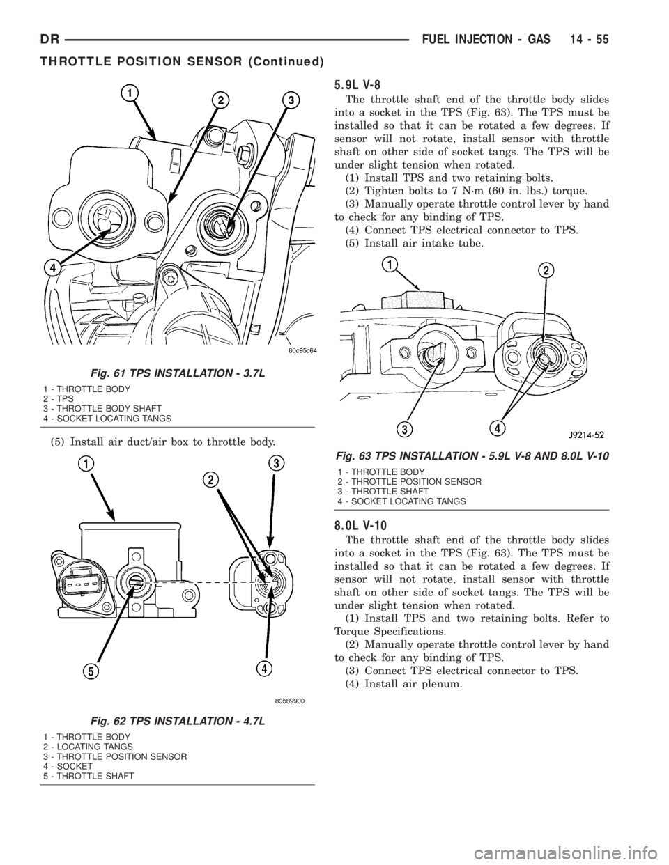
The throttle shaft end of the throttle body slides
into a socket in the TPS (Fig. 63). The TPS must be
installed so that it can be rotated a few degrees. If
sensor will not rotate, install sensor with throttle
shaft on other side of socket tangs. The TPS will be
under slight tension when rotated.
(1) Install TPS and two retaining bolts.
(2) Tighten bolts to 7 N´m (60 in. lbs.) torque.
(3) Manually operate throttle control lever by hand
to check for any binding of TPS.
(4) Connect TPS electrical connector to TPS.
(5) Install air intake tube.
8.0L V-10
The throttle shaft end of the throttle body slides
into a socket in the TPS (Fig. 63). The TPS must be
installed so that it can be rotated a few degrees. If
sensor will not rotate, install sensor with throttle
shaft on other side of socket tangs. The TPS will be
under slight tension when rotated.
(1) Install TPS and two retaining bolts. Refer to
Torque Specifications.
(2) Manually operate throttle control lever by hand
to check for any binding of TPS.
(3) Connect TPS electrical connector to TPS.
(4) Install air plenum.
Fig. 61 TPS INSTALLATION - 3.7L
1 - THROTTLE BODY
2 - TPS
3 - THROTTLE BODY SHAFT
4 - SOCKET LOCATING TANGS
Fig. 62 TPS INSTALLATION - 4.7L
1 - THROTTLE BODY
2 - LOCATING TANGS
3 - THROTTLE POSITION SENSOR
4 - SOCKET
5 - THROTTLE SHAFT
Fig. 63 TPS INSTALLATION - 5.9L V-8 AND 8.0L V-10
1 - THROTTLE BODY
2 - THROTTLE POSITION SENSOR
3 - THROTTLE SHAFT
4 - SOCKET LOCATING TANGS
DRFUEL INJECTION - GAS 14 - 55
THROTTLE POSITION SENSOR (Continued)
Page 1760 of 2895
(c) Position new element to canister lid. Place
this assembly into canister by rotating clockwise.
(d) Tighten cap to 34 N´m (25 ft. lbs.) torque. Do
not overtighten cap.
(3)Water-In-Fuel (WIF) Sensor:
(a) Install new o-ring seal to WIF sensor.
(b) Apply a light film of clean diesel oil to o-ring
seal.
(c) Install sensor into housing.
(d) Tighten sensor to 4.5 N´m (39 in. lbs.) torque.
(e) Connect electrical connector to WIF sensor.
(4)Fuel Heater Element:
(a) Install fuel heater into fuel filter housing.
(b) Install fuel heater thermostat into fuel filter
housing.
(c) Install fuel heater mounting screws and
tighten to 1-1.5 N´m torque.
(d) Connect electrical connector to fuel heater
thermostat.
(e) Install new filter cover O-ring onto fuel filter
housing cover and lubricate with 30W oil.
(f) Tighten fuel filter housing cover (lid) to 34
N´m (25 ft. lbs.).
(5)Drain Valve:
(a) Install 2 new o-rings to valve and filter hous-
ing.
(b) Lubricate with silicon grease.
(c) Install fuel drain valve.
(d) Install 4 mounting screws and tighten to
1±1.5 N´m (8±13 in. lbs.) torque.
(e) Connect drain hose to drain valve.
(6) Start engine and check for leaks.
FUEL HEATER
DESCRIPTION
The fuel heater assembly is located on the side of
the fuel filter housing (Fig. 3) or (Fig. 4).
The heater/element assembly is equipped with a
temperature sensor (thermostat) that senses fuel
temperature. This sensor is attached to the fuel heat-
er/element assembly.
OPERATION
The fuel heater is used to prevent diesel fuel from
waxing during cold weather operation.
When the temperature is below 45 8 degrees F,
the temperature sensor allows current to flow to the
heater element warming the fuel. When the temper-
ature is above 75 8 degrees F, the sensor stops cur-
rent flow to the heater element.
Battery voltage to operate the fuel heater element
is supplied from the ignition switch and through the
fuel heater relay. Also refer to Fuel Heater Relay.The fuel heater element and fuel heater relay
are not computer controlled.
The heater element operates on 12 volts, 300 watts
at 0 degrees F.
DIAGNOSIS AND TESTING - FUEL HEATER
The fuel heater is used to prevent diesel fuel from
waxing during cold weather operation.
NOTE: The fuel heater element, fuel heater relay
and fuel heater temperature sensor are not con-
trolled by the Engine Control Module (ECM), or the
Powertrain Control Module (PCM).
A malfunctioning fuel heater can cause a wax
build-up in the fuel filter/water separator. Wax
build-up in the filter/separator can cause engine
starting problems and prevent the engine from rev-
ving up. It can also cause blue or white fog-like
exhaust. If the heater is not operating in cold tem-
peratures, the engine may not operate due to fuel
waxing.
The fuel heater assembly is located on the side of
fuel filter housing.
The heater assembly is equipped with a built-in
fuel temperature sensor (thermostat) that senses fuel
temperature. When fuel temperature drops below 45
degrees 8 degrees F, the sensor allows current to
flow to built-in heater element to warm fuel. When
fuel temperature rises above 75 degrees 8 degrees
F, the sensor stops current flow to heater element
(circuit is open).
Voltage to operate fuel heater element is supplied
from ignition switch, through fuel heater relay (also
refer to Fuel Heater Relay), to fuel temperature sen-
sor and on to fuel heater element.
The heater element operates on 12 volts, 300 watts
at 0 degrees F. As temperature increases, power
requirements decrease.
A minimum of 7 volts is required to operate fuel
heater. The resistance value of heater element is less
than 1 ohm (cold) and up to 1000 ohms warm.
TESTING
(1) Disconnect electrical connector from thermostat
(Fig. 3) or (Fig. 4).
Ambient temperature must be below circuit close
temperature, If necessary, induce this ambient tem-
perature by placing ice packs on thermostat to pro-
duce an effective ambient temperature below circuit
close temperature. For first check of thermostat you
can hear click of thermostat when circuit closes.
Measure resistance across two pins. Operating
range is 0.3 Ð 0.45 Ohms.
(2) If resistance is out of range, remove thermostat
and check resistance across terminal connections of
DRFUEL DELIVERY - DIESEL 14 - 63
FUEL FILTER / WATER SEPARATOR (Continued)
Page 1765 of 2895
(4) Apply clean engine oilto injection pump
o-ring only.
The machined tapers on both injection pump
shaft and injection pump gear must be abso-
lutely dry, clean and free of any dirt or oil film.
This will ensure proper gear-to-shaft tighten-
ing.
(5) Clean pump gear and pump shaft at machined
tapers with an evaporative type cleaner such as
brake cleaner.
(6) Position injection pump to mounting flange on
gear cover while aligning injection pump shaft
through back of injection pump gear.
(7) After pump is positioned flat to mounting
flange, install 3 pump mounting nuts and tighten
finger tight only.Do not attempt a final tightening
at this time.Do not attempt to tighten (pull)
pump to gear cover using mounting nuts. Dam-
age to pump or gear cover may occur. The
pump must be positioned flat to its mounting
flange before attempting to tighten 3 mounting
nuts.
(8) To prevent damage or cracking of components,
install and tighten nuts in the following sequence:
(a) Install injection pump shaft washer and nut
to pump shaft. Tighten nutfinger tight only.
(b) Do preliminary (light) tightening of injection
pump shaft nut.
(c) Tighten 3 injection pump mounting nuts to 8
N´m (70.8 in. lbs.).
(d) Do a final tightening of pump shaft nut to
105 N´m (77 ft. lbs.).
(9) Install drive gear access cover (plate) using a
1/2 inch drive ratchet. Plate is threaded to timing
gear cover.
(10) Install Engine Control Module (ECM) to left
side of engine.
(11) Install fuel line (injection pump-to-overflow
valve). Tighten bolts to 24 N´m (17 ft. lbs.) torque.
(12) Install fuel line (injection pump-to-fuel rail).
Tighten to 24 N´m (17 ft. lbs.) torque.
(13) Install fuel line (injection pump-to-fuel filter
housing). Tighten to 24 N´m (17 ft. lbs.) torque.
(14) Connect Fuel Control Actuator (FCA) electri-
cal connector to rear of injection pump.
(15) Install intake manifold air intake tube (above
injection pump). Tighten clamps.
(16) Install accessory drive belt.
(17) Install cooling fan shroud.
(18) Install cooling fan assembly.
(19) Connect both negative battery cables to both
batteries.
(20) Check system for fuel or engine oil leaks.FUEL LEVEL SENDING UNIT /
SENSOR
DESCRIPTION
The fuel gauge sending unit (fuel level sensor) is
attached to the side of the fuel tank module. The
sending unit consists of a float, an arm, and a vari-
able resistor track (card).
OPERATION
The fuel tank module on diesel powered models
has 3 different circuits (wires). Two of these circuits
are used at the fuel gauge sending unit for fuel
gauge operation. The other wire is used for a ground.
The diesel engine does not have a fuel tank module
mounted electric fuel pump. The electric fuel pump
(fuel transfer pump) is mounted to the engine.
For Fuel Gauge Operation:A constant input
voltage source of about 12 volts (battery voltage) is
supplied to the resistor track on the fuel gauge send-
ing unit. This is fed directly from the Powertrain
Control Module (PCM).NOTE: For diagnostic pur-
poses, this 12V power source can only be veri-
fied with the circuit opened (fuel tank module
electrical connector unplugged). With the con-
nectors plugged, output voltages will vary from
about .6 volts at FULL, to about 7.0 volts at
EMPTY.The resistor track is used to vary the volt-
age (resistance) depending on fuel tank float level. As
fuel level increases, the float and arm move up,
which decreases voltage. As fuel level decreases, the
float and arm move down, which increases voltage.
The varied voltage signal is returned back to the
ECM through the sensor return circuit.
Both of the electrical circuits between the fuel
gauge sending unit and the ECM are hard-wired (not
multi-plexed). After the voltage signal is sent from
the resistor track, and back to the ECM, the ECM
will interpret the resistance (voltage) data and send
a message across the multi-plex bus circuits to the
instrument panel cluster. Here it is translated into
the appropriate fuel gauge level reading. Refer to
Instrument Panel for additional information.
REMOVAL
REMOVAL/INSTALLATION
For diesel removal and installation procedures,
refer to the gas section of Fuel System/Fuel Delivery.
See Fuel Level Sending Unit/Sensor Removal/Instal-
lation.
14 - 68 FUEL DELIVERY - DIESELDR
FUEL INJECTION PUMP (Continued)
Page 1780 of 2895
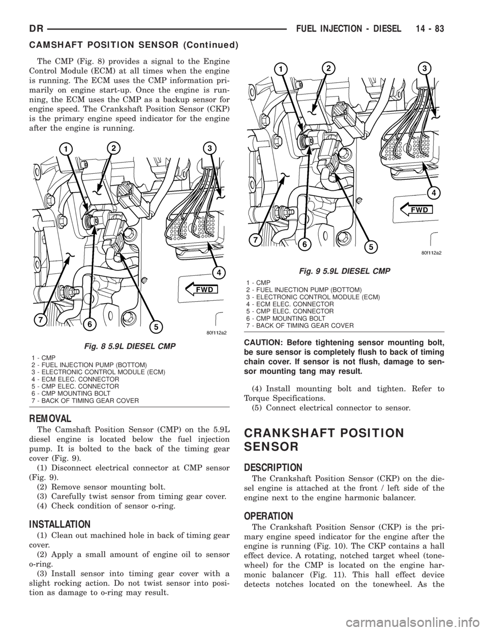
The CMP (Fig. 8) provides a signal to the Engine
Control Module (ECM) at all times when the engine
is running. The ECM uses the CMP information pri-
marily on engine start-up. Once the engine is run-
ning, the ECM uses the CMP as a backup sensor for
engine speed. The Crankshaft Position Sensor (CKP)
is the primary engine speed indicator for the engine
after the engine is running.
REMOVAL
The Camshaft Position Sensor (CMP) on the 5.9L
diesel engine is located below the fuel injection
pump. It is bolted to the back of the timing gear
cover (Fig. 9).
(1) Disconnect electrical connector at CMP sensor
(Fig. 9).
(2) Remove sensor mounting bolt.
(3) Carefully twist sensor from timing gear cover.
(4) Check condition of sensor o-ring.
INSTALLATION
(1) Clean out machined hole in back of timing gear
cover.
(2) Apply a small amount of engine oil to sensor
o-ring.
(3) Install sensor into timing gear cover with a
slight rocking action. Do not twist sensor into posi-
tion as damage to o-ring may result.CAUTION: Before tightening sensor mounting bolt,
be sure sensor is completely flush to back of timing
chain cover. If sensor is not flush, damage to sen-
sor mounting tang may result.
(4) Install mounting bolt and tighten. Refer to
Torque Specifications.
(5) Connect electrical connector to sensor.
CRANKSHAFT POSITION
SENSOR
DESCRIPTION
The Crankshaft Position Sensor (CKP) on the die-
sel engine is attached at the front / left side of the
engine next to the engine harmonic balancer.
OPERATION
The Crankshaft Position Sensor (CKP) is the pri-
mary engine speed indicator for the engine after the
engine is running (Fig. 10). The CKP contains a hall
effect device. A rotating, notched target wheel (tone-
wheel) for the CMP is located on the engine har-
monic balancer (Fig. 11). This hall effect device
detects notches located on the tonewheel. As the
Fig. 8 5.9L DIESEL CMP
1 - CMP
2 - FUEL INJECTION PUMP (BOTTOM)
3 - ELECTRONIC CONTROL MODULE (ECM)
4 - ECM ELEC. CONNECTOR
5 - CMP ELEC. CONNECTOR
6 - CMP MOUNTING BOLT
7 - BACK OF TIMING GEAR COVER
Fig. 9 5.9L DIESEL CMP
1 - CMP
2 - FUEL INJECTION PUMP (BOTTOM)
3 - ELECTRONIC CONTROL MODULE (ECM)
4 - ECM ELEC. CONNECTOR
5 - CMP ELEC. CONNECTOR
6 - CMP MOUNTING BOLT
7 - BACK OF TIMING GEAR COVER
DRFUEL INJECTION - DIESEL 14 - 83
CAMSHAFT POSITION SENSOR (Continued)
Page 1782 of 2895
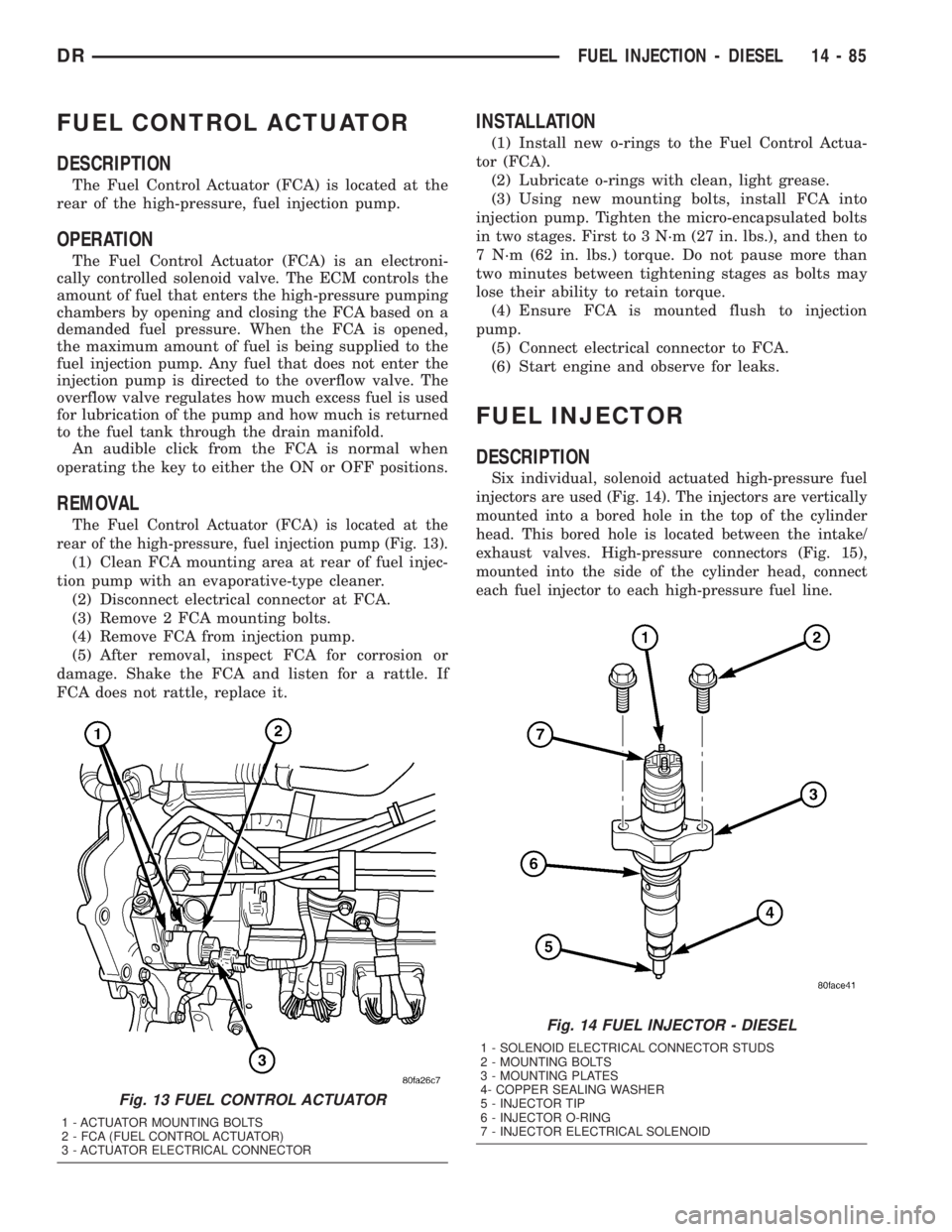
FUEL CONTROL ACTUATOR
DESCRIPTION
The Fuel Control Actuator (FCA) is located at the
rear of the high-pressure, fuel injection pump.
OPERATION
The Fuel Control Actuator (FCA) is an electroni-
cally controlled solenoid valve. The ECM controls the
amount of fuel that enters the high-pressure pumping
chambers by opening and closing the FCA based on a
demanded fuel pressure. When the FCA is opened,
the maximum amount of fuel is being supplied to the
fuel injection pump. Any fuel that does not enter the
injection pump is directed to the overflow valve. The
overflow valve regulates how much excess fuel is used
for lubrication of the pump and how much is returned
to the fuel tank through the drain manifold.
An audible click from the FCA is normal when
operating the key to either the ON or OFF positions.
REMOVAL
The Fuel Control Actuator (FCA) is located at the
rear of the high-pressure, fuel injection pump (Fig. 13).
(1) Clean FCA mounting area at rear of fuel injec-
tion pump with an evaporative-type cleaner.
(2) Disconnect electrical connector at FCA.
(3) Remove 2 FCA mounting bolts.
(4) Remove FCA from injection pump.
(5) After removal, inspect FCA for corrosion or
damage. Shake the FCA and listen for a rattle. If
FCA does not rattle, replace it.
INSTALLATION
(1) Install new o-rings to the Fuel Control Actua-
tor (FCA).
(2) Lubricate o-rings with clean, light grease.
(3) Using new mounting bolts, install FCA into
injection pump. Tighten the micro-encapsulated bolts
in two stages. First to 3 N´m (27 in. lbs.), and then to
7 N´m (62 in. lbs.) torque. Do not pause more than
two minutes between tightening stages as bolts may
lose their ability to retain torque.
(4) Ensure FCA is mounted flush to injection
pump.
(5) Connect electrical connector to FCA.
(6) Start engine and observe for leaks.
FUEL INJECTOR
DESCRIPTION
Six individual, solenoid actuated high-pressure fuel
injectors are used (Fig. 14). The injectors are vertically
mounted into a bored hole in the top of the cylinder
head. This bored hole is located between the intake/
exhaust valves. High-pressure connectors (Fig. 15),
mounted into the side of the cylinder head, connect
each fuel injector to each high-pressure fuel line.
Fig. 13 FUEL CONTROL ACTUATOR
1 - ACTUATOR MOUNTING BOLTS
2 - FCA (FUEL CONTROL ACTUATOR)
3 - ACTUATOR ELECTRICAL CONNECTOR
Fig. 14 FUEL INJECTOR - DIESEL
1 - SOLENOID ELECTRICAL CONNECTOR STUDS
2 - MOUNTING BOLTS
3 - MOUNTING PLATES
4- COPPER SEALING WASHER
5 - INJECTOR TIP
6 - INJECTOR O-RING
7 - INJECTOR ELECTRICAL SOLENOID
DRFUEL INJECTION - DIESEL 14 - 85
Page 1785 of 2895
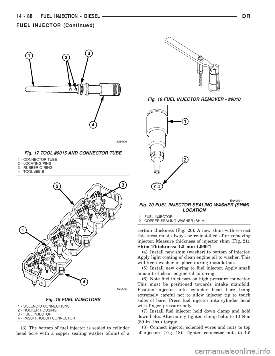
(3) The bottom of fuel injector is sealed to cylinder
head bore with a copper sealing washer (shim) of acertain thickness (Fig. 20). A new shim with correct
thickness must always be re-installed after removing
injector. Measure thickness of injector shim (Fig. 21).
Shim Thickness: 1.5 mm (.060º)
(4) Install new shim (washer) to bottom of injector.
Apply light coating of clean engine oil to washer. This
will keep washer in place during installation.
(5) Install new o-ring to fuel injector. Apply small
amount of clean engine oil to o-ring.
(6) Note fuel inlet port on high pressure connector.
This must be positioned towards intake manifold.
Position injector into cylinder head bore being
extremely careful not to allow injector tip to touch
sides of bore. Press fuel injector into cylinder head
with finger pressure only.
(7) Install fuel injector hold down clamp and hold
down bolts. Alternately tighten clamp bolts to 10 N´m
(89 in. lbs.) torque.
(8) Connect injector solenoid wires and nuts to top
of injectors (Fig. 18). Tighten connector nuts to 1.5
Fig. 17 TOOL #9015 AND CONNECTOR TUBE
1 - CONNECTOR TUBE
2 - LOCATING PINS
3 - RUBBER O-RING
4 - TOOL #9015
Fig. 18 FUEL INJECTORS
1 - SOLENOID CONNECTIONS
2 - ROCKER HOUSING
3 - FUEL INJECTOR
4 - PASSTHROUGH CONNECTOR
Fig. 19 FUEL INJECTOR REMOVER - #9010
Fig. 20 FUEL INJECTOR SEALING WASHER (SHIM)
LOCATION
1 - FUEL INJECTOR
2 - COPPER SEALING WASHER (SHIM)
14 - 88 FUEL INJECTION - DIESELDR
FUEL INJECTOR (Continued)
Page 1787 of 2895
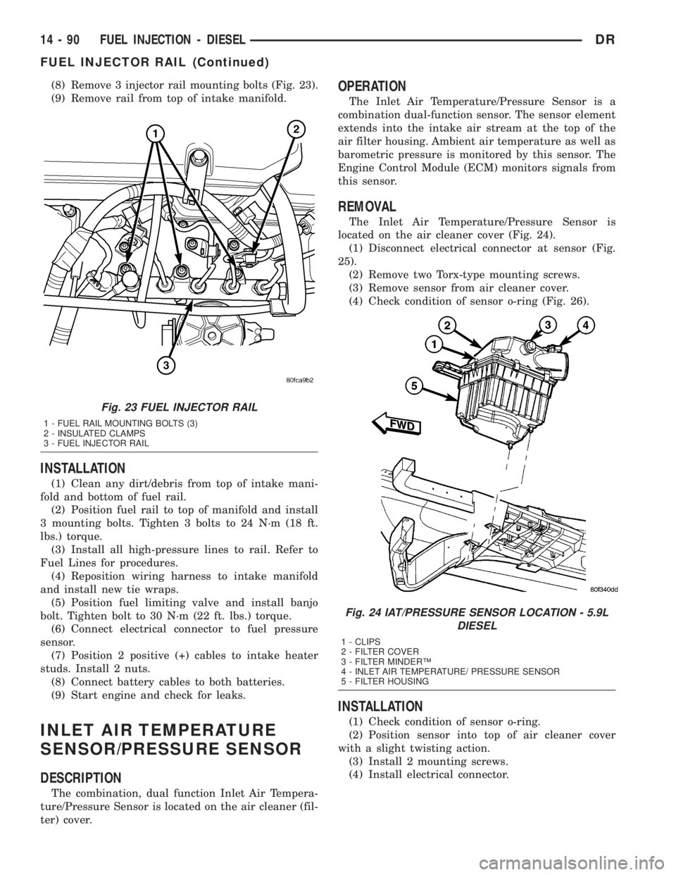
(8) Remove 3 injector rail mounting bolts (Fig. 23).
(9) Remove rail from top of intake manifold.
INSTALLATION
(1) Clean any dirt/debris from top of intake mani-
fold and bottom of fuel rail.
(2) Position fuel rail to top of manifold and install
3 mounting bolts. Tighten 3 bolts to 24 N´m (18 ft.
lbs.) torque.
(3) Install all high-pressure lines to rail. Refer to
Fuel Lines for procedures.
(4) Reposition wiring harness to intake manifold
and install new tie wraps.
(5) Position fuel limiting valve and install banjo
bolt. Tighten bolt to 30 N´m (22 ft. lbs.) torque.
(6) Connect electrical connector to fuel pressure
sensor.
(7) Position 2 positive (+) cables to intake heater
studs. Install 2 nuts.
(8) Connect battery cables to both batteries.
(9) Start engine and check for leaks.
INLET AIR TEMPERATURE
SENSOR/PRESSURE SENSOR
DESCRIPTION
The combination, dual function Inlet Air Tempera-
ture/Pressure Sensor is located on the air cleaner (fil-
ter) cover.
OPERATION
The Inlet Air Temperature/Pressure Sensor is a
combination dual-function sensor. The sensor element
extends into the intake air stream at the top of the
air filter housing. Ambient air temperature as well as
barometric pressure is monitored by this sensor. The
Engine Control Module (ECM) monitors signals from
this sensor.
REMOVAL
The Inlet Air Temperature/Pressure Sensor is
located on the air cleaner cover (Fig. 24).
(1) Disconnect electrical connector at sensor (Fig.
25).
(2) Remove two Torx-type mounting screws.
(3) Remove sensor from air cleaner cover.
(4) Check condition of sensor o-ring (Fig. 26).
INSTALLATION
(1) Check condition of sensor o-ring.
(2) Position sensor into top of air cleaner cover
with a slight twisting action.
(3) Install 2 mounting screws.
(4) Install electrical connector.
Fig. 23 FUEL INJECTOR RAIL
1 - FUEL RAIL MOUNTING BOLTS (3)
2 - INSULATED CLAMPS
3 - FUEL INJECTOR RAIL
Fig. 24 IAT/PRESSURE SENSOR LOCATION - 5.9L
DIESEL
1 - CLIPS
2 - FILTER COVER
3 - FILTER MINDERŸ
4 - INLET AIR TEMPERATURE/ PRESSURE SENSOR
5 - FILTER HOUSING
14 - 90 FUEL INJECTION - DIESELDR
FUEL INJECTOR RAIL (Continued)
Page 1801 of 2895
(12) Release the shift cable from the column
bracket and remove it from the bracket.
(13) Remove the SKIM module in order to discon-
nect the electrical connector.
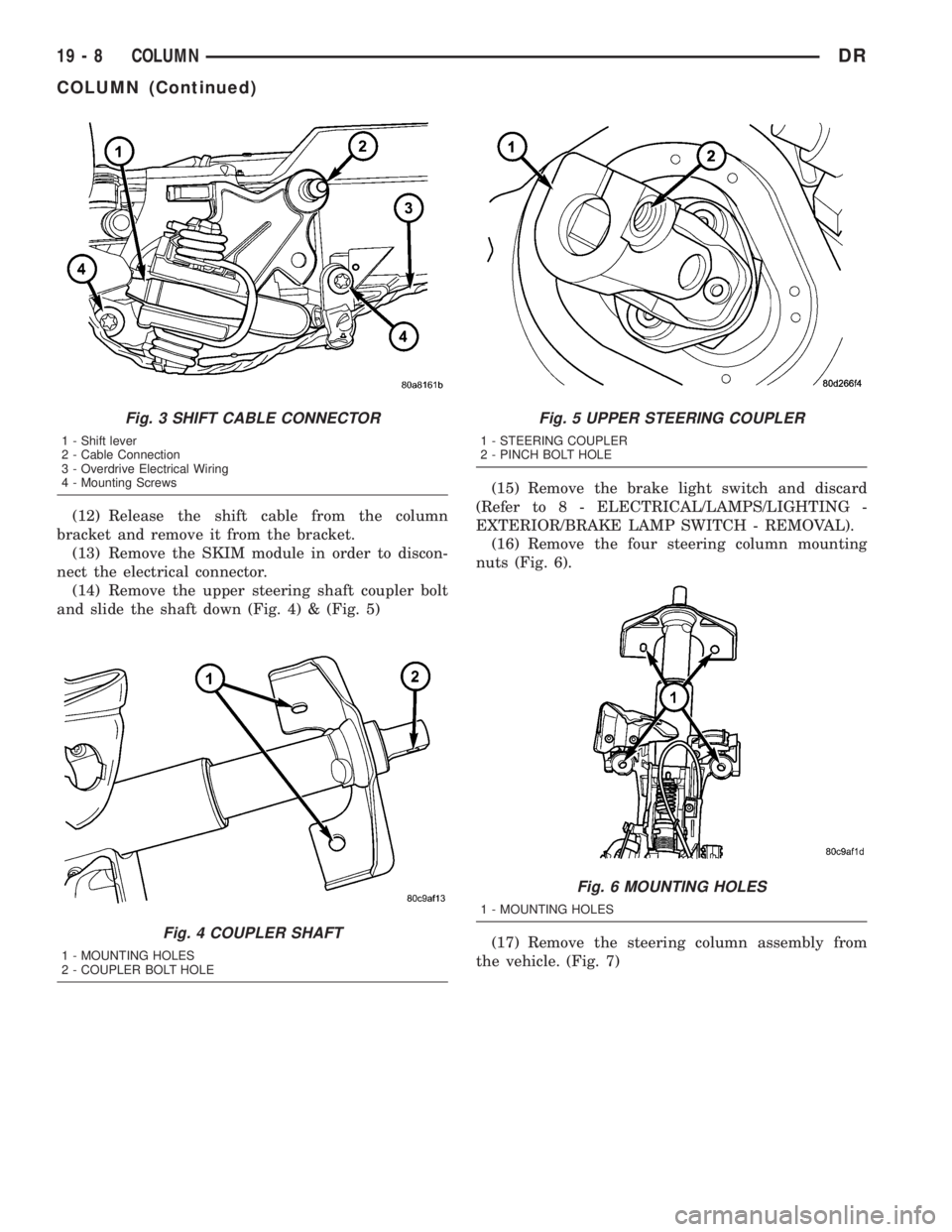
(14) Remove the upper steering shaft coupler bolt
and slide the shaft down (Fig. 4) & (Fig. 5)(15) Remove the brake light switch and discard
(Refer to 8 - ELECTRICAL/LAMPS/LIGHTING -
EXTERIOR/BRAKE LAMP SWITCH - REMOVAL).
(16) Remove the four steering column mounting
nuts (Fig. 6).
(17) Remove the steering column assembly from
the vehicle. (Fig. 7)
Fig. 3 SHIFT CABLE CONNECTOR
1 - Shift lever
2 - Cable Connection
3 - Overdrive Electrical Wiring
4 - Mounting Screws
Fig. 4 COUPLER SHAFT
1 - MOUNTING HOLES
2 - COUPLER BOLT HOLE
Fig. 5 UPPER STEERING COUPLER
1 - STEERING COUPLER
2 - PINCH BOLT HOLE
Fig. 6 MOUNTING HOLES
1 - MOUNTING HOLES
19 - 8 COLUMNDR
COLUMN (Continued)