2003 DODGE RAM light
[x] Cancel search: lightPage 1584 of 2895
VIBRATION DAMPER
REMOVAL
(1) Remove the accessory drive belt (Refer to 7 -
COOLING/ACCESSORY DRIVE/DRIVE BELTS -
REMOVAL).
(2) Remove the four (4) damper to crankshaft bolts
and remove damper and speed indicator ring.
INSPECTION
(1) Inspect the damper hub for cracks and replace
if any are found.
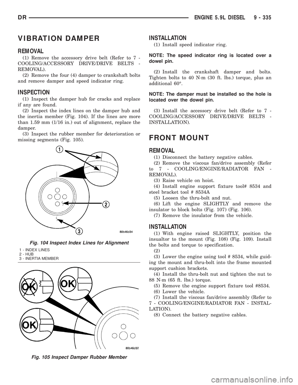
(2) Inspect the index lines on the damper hub and
the inertia member (Fig. 104). If the lines are more
than 1.59 mm (1/16 in.) out of alignment, replace the
damper.
(3) Inspect the rubber member for deterioration or
missing segments (Fig. 105).
INSTALLATION
(1) Install speed indicator ring.
NOTE: The speed indicator ring is located over a
dowel pin.
(2) Install the crankshaft damper and bolts.
Tighten bolts to 40 N´m (30 ft. lbs.) torque, plus an
additional 60É.
NOTE: The damper must be installed so the hole is
located over the dowel pin.
(3) Install the accessory drive belt (Refer to 7 -
COOLING/ACCESSORY DRIVE/DRIVE BELTS -
INSTALLATION).
FRONT MOUNT
REMOVAL
(1) Disconnect the battery negative cables.
(2) Remove the viscous fan/drive assembly (Refer
to 7 - COOLING/ENGINE/RADIATOR FAN -
REMOVAL).
(3) Raise vehicle on hoist.
(4) Install engine support fixture tool# 8534 and
steel bracket tool # 8534A
(5) Loosen the thru-bolt and nut.
(6) Lift the engine SLIGHTLY and remove the
insulator to block bolts (Fig. 107) (Fig. 106).
(7) Remove the insulator from the vehicle.
INSTALLATION
(1) With engine raised SLIGHTLY, position the
insualtor to the mount (Fig. 108) (Fig. 109). Install
the bolts and torque to specification.
(2)
(3) Lower the engine using tool # 8534, while guid-
ing the mount and thru-bolt into the frame mounted
support cushion brackets.
(4) Install the thru-bolt nut and tighten the nut to
88 N´m (65 ft. lbs.) torque.
(5) Remove the engine support fixture tool #8534.
(6) Lower the vehicle.
(7) Install the viscous fan/drive assembly (Refer to
7 - COOLING/ENGINE/RADIATOR FAN - INSTAL-
LATION).
(8) Connect the battery negative cables.
Fig. 104 Inspect Index Lines for Alignment
1 - INDEX LINES
2 - HUB
3 - INERTIA MEMBER
Fig. 105 Inspect Damper Rubber Member
DRENGINE 5.9L DIESEL 9 - 335
Page 1586 of 2895
REAR MOUNT
REMOVAL
(1) Raise the vehicle on a hoist.
(2) Position a transmission jack in place.
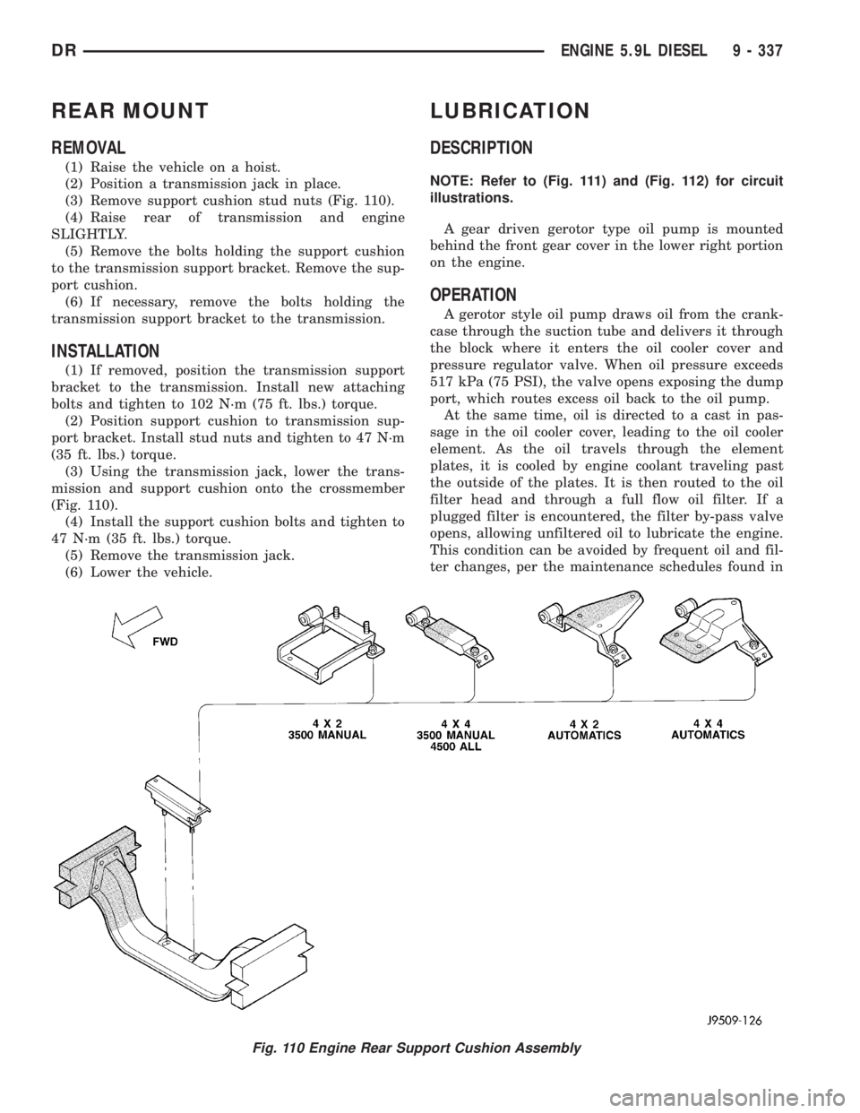
(3) Remove support cushion stud nuts (Fig. 110).
(4) Raise rear of transmission and engine
SLIGHTLY.
(5) Remove the bolts holding the support cushion
to the transmission support bracket. Remove the sup-
port cushion.
(6) If necessary, remove the bolts holding the
transmission support bracket to the transmission.
INSTALLATION
(1) If removed, position the transmission support
bracket to the transmission. Install new attaching
bolts and tighten to 102 N´m (75 ft. lbs.) torque.
(2) Position support cushion to transmission sup-
port bracket. Install stud nuts and tighten to 47 N´m
(35 ft. lbs.) torque.
(3) Using the transmission jack, lower the trans-
mission and support cushion onto the crossmember
(Fig. 110).
(4) Install the support cushion bolts and tighten to
47 N´m (35 ft. lbs.) torque.
(5) Remove the transmission jack.
(6) Lower the vehicle.
LUBRICATION
DESCRIPTION
NOTE: Refer to (Fig. 111) and (Fig. 112) for circuit
illustrations.
A gear driven gerotor type oil pump is mounted
behind the front gear cover in the lower right portion
on the engine.
OPERATION
A gerotor style oil pump draws oil from the crank-
case through the suction tube and delivers it through
the block where it enters the oil cooler cover and
pressure regulator valve. When oil pressure exceeds
517 kPa (75 PSI), the valve opens exposing the dump
port, which routes excess oil back to the oil pump.
At the same time, oil is directed to a cast in pas-
sage in the oil cooler cover, leading to the oil cooler
element. As the oil travels through the element
plates, it is cooled by engine coolant traveling past
the outside of the plates. It is then routed to the oil
filter head and through a full flow oil filter. If a
plugged filter is encountered, the filter by-pass valve
opens, allowing unfiltered oil to lubricate the engine.
This condition can be avoided by frequent oil and fil-
ter changes, per the maintenance schedules found in
Fig. 110 Engine Rear Support Cushion Assembly
DRENGINE 5.9L DIESEL 9 - 337
Page 1591 of 2895
OIL COOLER & LINES
CLEANING
CLEANING AND INSPECTION
Clean the sealing surfaces.
Apply 483 kPa (70 psi) air pressure to the element
to check for leaks. If the element leaks, replace the
element.
OIL FILTER
REMOVAL
(1) Clean the area around the oil filter head.
Remove the filter from below using a cap-style filter
wrench.
(2) Clean the gasket surface of the filter head. The
filter canister O-Ring seal can stick on the filter
head. Make sure it is removed.
INSTALLATION
(1) Fill the oil filter element with clean oil before
installation. Use the same type oil that will be used
in the engine.
(2) Apply a light film of lubricating oil to the seal-
ing surface before installing the filter.
CAUTION: Mechanical over-tightening may distort
the threads or damage the filter element seal.
(3) Install the filter until it contacts the sealing
surface of the oil filter adapter. Tighten filter an
additional
1¤2turn.
OIL PAN
REMOVAL
(1) Disconnect the battery negative cables.
(2) Install engine support fixture # 8534.
(3) Raise vehicle on hoist.
(4) Disconnect starter cables from starter motor.
(5) Remove starter motor (Refer to 8 - ELECTRI-
CAL/STARTING/STARTER MOTOR - REMOVAL)
and transmission adapter plate assembly.
(6) Remove transmission and transfer case (if
equipped).
(7) Remove flywheel or flexplate.
(8) Remove the transmission adapter plate.
WARNING: HOT OIL CAN CAUSE PERSONAL
INJURY.
(9) Drain the engine oil (Refer to 9 - ENGINE/LU-
BRICATION/OIL - STANDARD PROCEDURE).(10) Install the oil pan drain plug if sealing sur-
face is not damaged and tighten to 50 N´m (57 ft.
lbs.) torque.
(11) Remove oil pan bolts, break the pan to block
seal, and lower pan slightly and remove oil suction
tube fasteners.
(12) Remove oil pan and suction tube.
CLEANING
Remove all gasket material from the oil pan and
cylinder block sealing surfaces. Extra effort may be
required around T-joint areas. Clean oil pan and
flush suction tube with a suitable solvent.
INSPECTION
Inspect the oil pan, suction tube, and tube braces
for cracks and damage. Replace any defective compo-
nent. Inspect the oil drain plug and drain hole
threads. Inspect the oil pan sealing surface for
straightness. Repair any minor imperfections with a
ball-peen hammer. Do not attempt to repair an oil
pan by welding.
INSTALLATION
(1) Fill the T-joint between the pan rail/gear hous-
ing and pan rail/rear seal retainer with sealant. Use
MopartSilicone Rubber Adhesive Sealant or equiva-
lent.
(2) Place suction tube in oil pan and guide them
into place. Using a new tube to block gasket, install
and tighten the suction tube bolts by hand. Starting
with the oil pump inlet bolts, tighten the bolts to 24
N´m (18 ft. lbs.) torque. Tighten the remaining tube
brace bolts to 43 N´m (32 ft. lbs.) torque.
(3) Starting in the center and working outward,
tighten the oil pan bolts to 28 N´m (21 ft. lbs.)
torque.
(4) Install the flywheel housing assembly with the
starter motor attached and tighten bolts to 77 N´m
(57 ft. lbs.) torque.
(5) Connect starter motor cables.
(6) Install the flywheel or flexplate. Torque to 137
N´m (101 ft. lbs.).
(7) Install transmission and transfer case (if
equipped).
(8) Lower vehicle.
(9) Remove the engine support fixture # 8534.
(10) Install battery negative cables.
(11) Fill the crankcase with new engine oil.
(12) Start engine and check for leaks. Stop engine,
check oil level, and adjust, if necessary.
9 - 342 ENGINE 5.9L DIESELDR
Page 1602 of 2895
ENGINE 8.0L
DESCRIPTION
The 8.0 Liter (488 CID) ten-cylinder engine is a
V-Type lightweight, single cam, overhead valve
engine with hydraulic roller tappets. This engine is
designed for unleaded fuel.
Engine lubrication system consists of a gerotor
type oil pump mounted in the timing chain cover and
driven by the crankshaft. The V-10 uses a full flow
oil filter.
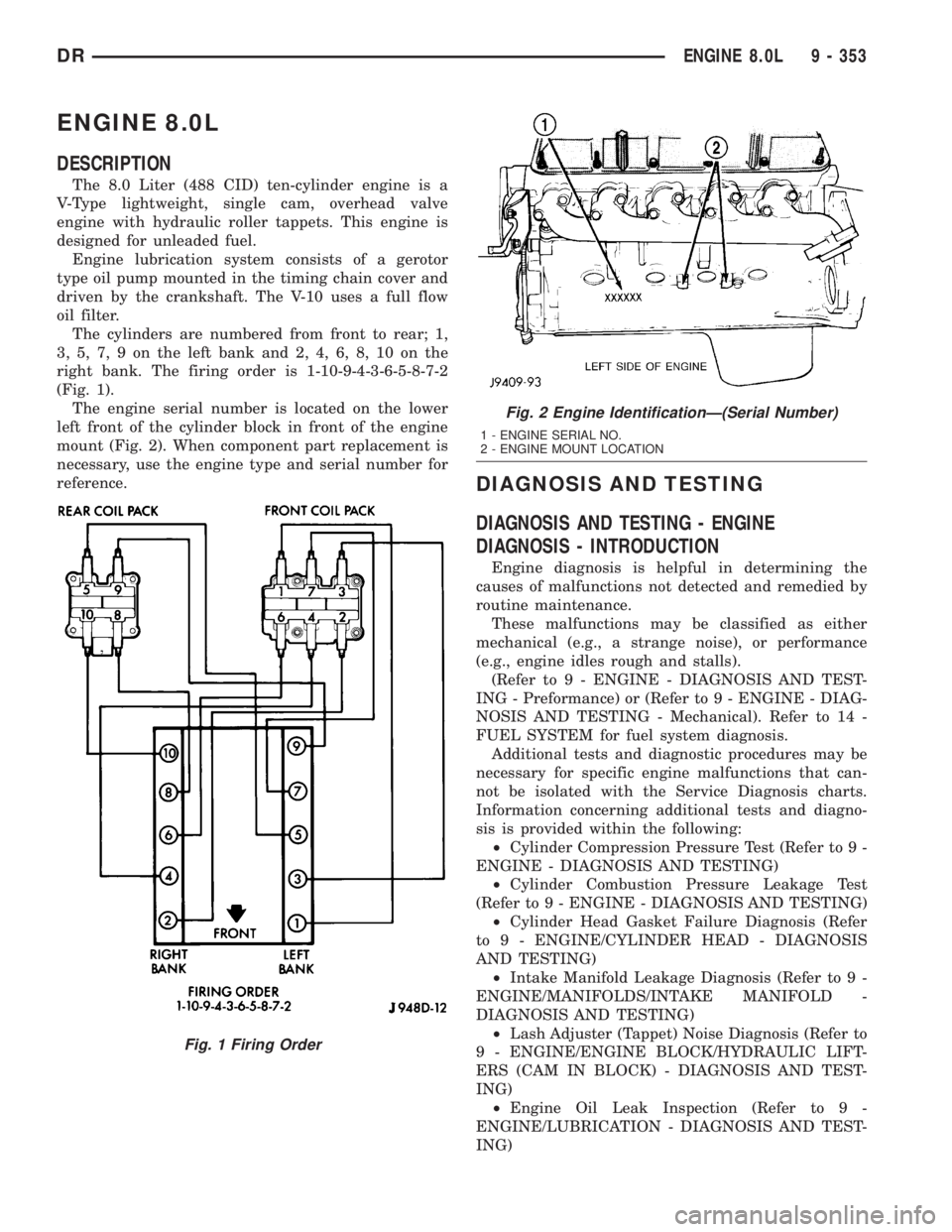
The cylinders are numbered from front to rear; 1,
3, 5, 7, 9 on the left bank and 2, 4, 6, 8, 10 on the
right bank. The firing order is 1-10-9-4-3-6-5-8-7-2
(Fig. 1).
The engine serial number is located on the lower
left front of the cylinder block in front of the engine
mount (Fig. 2). When component part replacement is
necessary, use the engine type and serial number for
reference.
DIAGNOSIS AND TESTING
DIAGNOSIS AND TESTING - ENGINE
DIAGNOSIS - INTRODUCTION
Engine diagnosis is helpful in determining the
causes of malfunctions not detected and remedied by
routine maintenance.
These malfunctions may be classified as either
mechanical (e.g., a strange noise), or performance
(e.g., engine idles rough and stalls).
(Refer to 9 - ENGINE - DIAGNOSIS AND TEST-
ING - Preformance) or (Refer to 9 - ENGINE - DIAG-
NOSIS AND TESTING - Mechanical). Refer to 14 -
FUEL SYSTEM for fuel system diagnosis.
Additional tests and diagnostic procedures may be
necessary for specific engine malfunctions that can-
not be isolated with the Service Diagnosis charts.
Information concerning additional tests and diagno-
sis is provided within the following:
²Cylinder Compression Pressure Test (Refer to 9 -
ENGINE - DIAGNOSIS AND TESTING)
²Cylinder Combustion Pressure Leakage Test
(Refer to 9 - ENGINE - DIAGNOSIS AND TESTING)
²Cylinder Head Gasket Failure Diagnosis (Refer
to 9 - ENGINE/CYLINDER HEAD - DIAGNOSIS
AND TESTING)
²Intake Manifold Leakage Diagnosis (Refer to 9 -
ENGINE/MANIFOLDS/INTAKE MANIFOLD -
DIAGNOSIS AND TESTING)
²Lash Adjuster (Tappet) Noise Diagnosis (Refer to
9 - ENGINE/ENGINE BLOCK/HYDRAULIC LIFT-
ERS (CAM IN BLOCK) - DIAGNOSIS AND TEST-
ING)
²Engine Oil Leak Inspection (Refer to 9 -
ENGINE/LUBRICATION - DIAGNOSIS AND TEST-
ING)
Fig. 1 Firing Order
Fig. 2 Engine IdentificationÐ(Serial Number)
1 - ENGINE SERIAL NO.
2 - ENGINE MOUNT LOCATION
DRENGINE 8.0L 9 - 353
Page 1609 of 2895
STANDARD PROCEDURE
STANDARD PROCEDUREÐCYLINDER BORE
HONING
Before honing, stuff plenty of clean shop towels
under the bores and over the crankshaft to keep
abrasive materials from entering the crankshaft
area.
(1) Used carefully, the Cylinder Bore Sizing Hone
C-823, equipped with 220 grit stones, is the best tool
for this job. In addition to deglazing, it will reduce
taper and out-of-round, as well as removing light
scuffing, scoring and scratches. Usually, a few strokes
will clean up a bore and maintain the required lim-
its.
CAUTION: DO NOT use rigid type hones to remove
cylinder wall glaze.
(2) Deglazing of the cylinder walls may be done if
the cylinder bore is straight and round. Use a cylin-
der surfacing hone, Honing Tool C-3501, equipped
with 280 grit stones (C-3501-3810). about 20-60
strokes, depending on the bore condition, will be suf-
ficient to provide a satisfactory surface. Using honing
oil C-3501-3880, or a light honing oil, available from
major oil distributors.
CAUTION: DO NOT use engine or transmission oil,
mineral spirits, or kerosene.
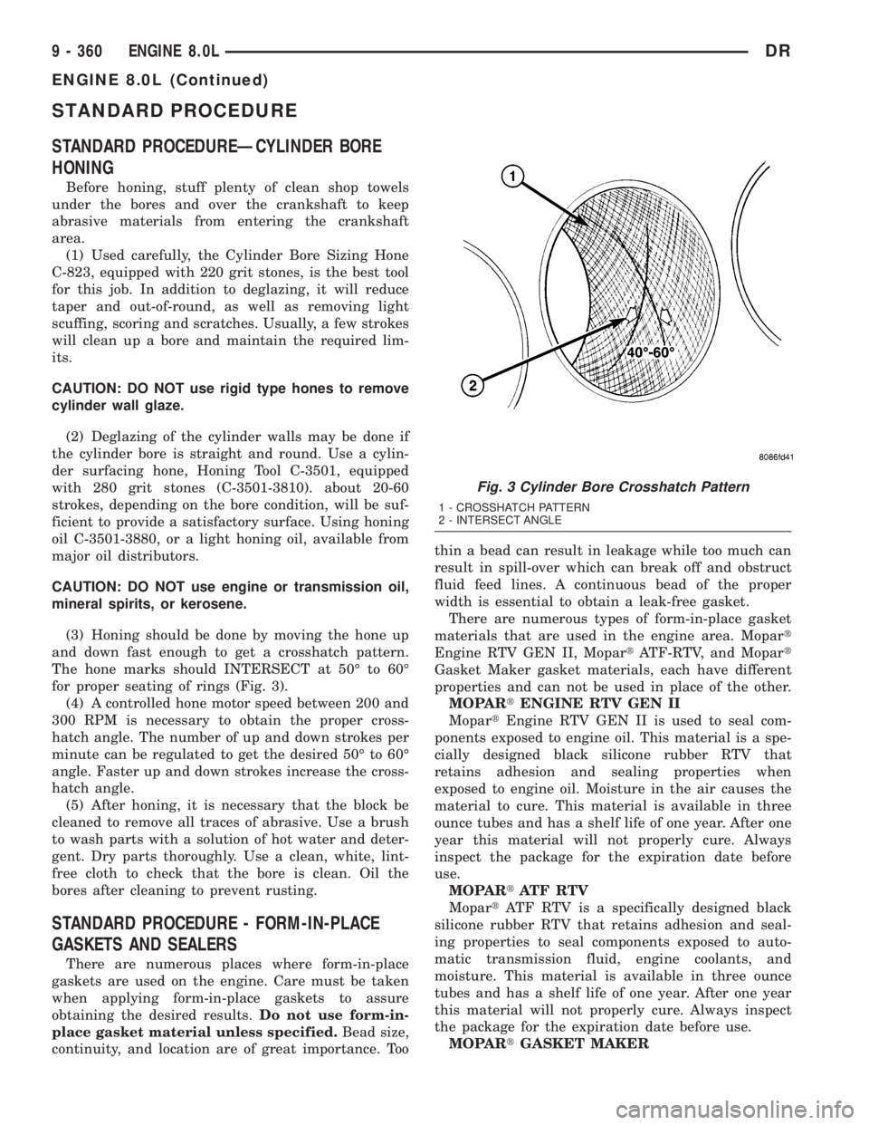
(3) Honing should be done by moving the hone up
and down fast enough to get a crosshatch pattern.
The hone marks should INTERSECT at 50É to 60É
for proper seating of rings (Fig. 3).
(4) A controlled hone motor speed between 200 and
300 RPM is necessary to obtain the proper cross-
hatch angle. The number of up and down strokes per
minute can be regulated to get the desired 50É to 60É
angle. Faster up and down strokes increase the cross-
hatch angle.
(5) After honing, it is necessary that the block be
cleaned to remove all traces of abrasive. Use a brush
to wash parts with a solution of hot water and deter-
gent. Dry parts thoroughly. Use a clean, white, lint-
free cloth to check that the bore is clean. Oil the
bores after cleaning to prevent rusting.
STANDARD PROCEDURE - FORM-IN-PLACE
GASKETS AND SEALERS
There are numerous places where form-in-place
gaskets are used on the engine. Care must be taken
when applying form-in-place gaskets to assure
obtaining the desired results.Do not use form-in-
place gasket material unless specified.Bead size,
continuity, and location are of great importance. Toothin a bead can result in leakage while too much can
result in spill-over which can break off and obstruct
fluid feed lines. A continuous bead of the proper
width is essential to obtain a leak-free gasket.
There are numerous types of form-in-place gasket
materials that are used in the engine area. Mopart
Engine RTV GEN II, MopartATF-RTV, and Mopart
Gasket Maker gasket materials, each have different
properties and can not be used in place of the other.
MOPARtENGINE RTV GEN II
MopartEngine RTV GEN II is used to seal com-
ponents exposed to engine oil. This material is a spe-
cially designed black silicone rubber RTV that
retains adhesion and sealing properties when
exposed to engine oil. Moisture in the air causes the
material to cure. This material is available in three
ounce tubes and has a shelf life of one year. After one
year this material will not properly cure. Always
inspect the package for the expiration date before
use.
MOPARtATF RTV
MopartATF RTV is a specifically designed black
silicone rubber RTV that retains adhesion and seal-
ing properties to seal components exposed to auto-
matic transmission fluid, engine coolants, and
moisture. This material is available in three ounce
tubes and has a shelf life of one year. After one year
this material will not properly cure. Always inspect
the package for the expiration date before use.
MOPARtGASKET MAKER
Fig. 3 Cylinder Bore Crosshatch Pattern
1 - CROSSHATCH PATTERN
2 - INTERSECT ANGLE
9 - 360 ENGINE 8.0LDR
ENGINE 8.0L (Continued)
Page 1621 of 2895
fuel line (Refer to 14 - FUEL SYSTEM/FUEL DELIV-
ERY/QUICK CONNECT FITTING - STANDARD
PROCEDURE).
(9) Disconnect accelerator linkage and if so
equipped, the speed control and transmission kick-
down cables.
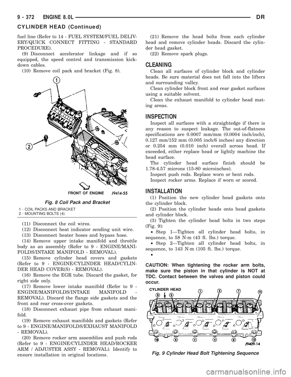
(10) Remove coil pack and bracket (Fig. 8).
(11) Disconnect the coil wires.
(12) Disconnect heat indicator sending unit wire.
(13) Disconnect heater hoses and bypass hose.
(14) Remove upper intake manifold and throttle
body as an assembly (Refer to 9 - ENGINE/MANI-
FOLDS/INTAKE MANIFOLD - REMOVAL).
(15) Remove cylinder head covers and gaskets
(Refer to 9 - ENGINE/CYLINDER HEAD/CYLIN-
DER HEAD COVER(S) - REMOVAL).
(16) Remove the EGR tube. Discard the gasket, for
right side only.
(17) Remove lower intake manifold (Refer to 9 -
ENGINE/MANIFOLDS/INTAKE MANIFOLD -
REMOVAL). Discard the flange side gaskets and the
front and rear cross-over gaskets.
(18) Disconnect exhaust pipe from exhaust mani-
fold.
(19) Remove exhaust manifolds and gaskets (Refer
to 9 - ENGINE/MANIFOLDS/EXHAUST MANIFOLD
- REMOVAL).
(20) Remove rocker arm assemblies and push rods
(Refer to 9 - ENGINE/CYLINDER HEAD/ROCKER
ARM / ADJUSTER ASSY - REMOVAL). Identify to
ensure installation in original locations.(21) Remove the head bolts from each cylinder
head and remove cylinder heads. Discard the cylin-
der head gasket.
(22) Remove spark plugs.
CLEANING
Clean all surfaces of cylinder block and cylinder
heads. Be sure material does not fall into the lifters
and surrounding valley.
Clean cylinder block front and rear gasket surfaces
using a suitable solvent.
Clean the exhaust manifold to cylinder head mat-
ing areas.
INSPECTION
Inspect all surfaces with a straightedge if there is
any reason to suspect leakage. The out-of-flatness
specifications are 0.0007 mm/mm (0.0004 inch/inch),
0.127 mm/152 mm (0.005 inch/6 inches) any direction
or 0.254 mm (0.010 inch) overall across head. If
exceeded, either replace head or lightly machine the
head surface.
The cylinder head surface finish should be
1.78-4.57 microns (15-80 microinches).
Inspect push rods. Replace worn or bent rods.
Inspect rocker arms. Replace if worn or scored.
INSTALLATION
(1) Position the new cylinder head gaskets onto
the cylinder block.
(2) Position the cylinder heads onto head gaskets
and cylinder block.
(3) Tighten the cylinder head bolts in two steps
(Fig. 9):
²Step 1ÐTighten all cylinder head bolts, in
sequence, to 58 N´m (43 ft. lbs.) torque.
²Step 2ÐTighten all cylinder head bolts, in
sequence, to 143 N´m (105 ft. lbs.) torque.
²
CAUTION: When tightening the rocker arm bolts,
make sure the piston in that cylinder is NOT at
TDC. Contact between the valves and piston could
occur.
Fig. 8 Coil Pack and Bracket
1 - COIL PACKS AND BRACKET
2 - MOUNTING BOLTS (4)
Fig. 9 Cylinder Head Bolt Tightening Sequence
9 - 372 ENGINE 8.0LDR
CYLINDER HEAD (Continued)
Page 1625 of 2895
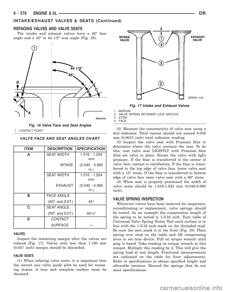
REFACING VALVES AND VALVE SEATS
The intake and exhaust valves have a 45É face
angle and a 45É to 44 1/2É seat angle (Fig. 16).
VALVE FACE AND SEAT ANGLES CHART
ITEM DESCRIPTION SPECIFICATION
ASEAT WIDTH 1.016 - 1.524
mm
INTAKE (0.040 - 0.060
in.)
SEAT WIDTH 1.016 - 1.524
mm
EXHAUST (0.040 - 0.060
in.)
BFACE ANGLE
(INT. and EXT.) 45É
CSEAT ANGLE
(INT. and EXT.) 44
1¤2É
DCONTACT
SURFACE Ð
VALVES
Inspect the remaining margin after the valves are
refaced (Fig. 17). Valves with less than 1.190 mm
(0.047 inch) margin should be discarded.
VALVE SEATS
(1) When refacing valve seats, it is important that
the correct size valve guide pilot be used for reseat-
ing stones. A true and complete surface must be
obtained.(2) Measure the concentricity of valve seat using a
dial indicator. Total runout should not exceed 0.038
mm (0.0015 inch) total indicator reading.
(3) Inspect the valve seat with Prussian blue to
determine where the valve contacts the seat. To do
this, coat valve seat LIGHTLY with Prussian blue
then set valve in place. Rotate the valve with light
pressure. If the blue is transferred to the center of
valve face, contact is satisfactory. If the blue is trans-
ferred to the top edge of valve face, lower valve seat
with a 15É stone. If the blue is transferred to bottom
edge of valve face raise valve seat with a 60É stone.
(4) When seat is properly positioned the width of
valve seats should be 1.016-1.524 mm (0.040-0.060
inch).
VALVE SPRING INSPECTION
Whenever valves have been removed for inspection,
reconditioning or replacement, valve springs should
be tested. As an example the compression length of
the spring to be tested is 1-5/16 inch. Turn table of
Universal Valve Spring Tester Tool until surface is in
line with the 1-5/16 inch mark on the threaded stud.
Be sure the zero mark is to the front (Fig. 18). Place
spring over stud on the table and lift compressing
lever to set tone device. Pull on torque wrench until
ping is heard. Take reading on torque wrench at this
instant. Multiply this reading by 2. This will give the
spring load at test length. Fractional measurements
are indicated on the table for finer adjustments.
Refer to specifications to obtain specified height and
allowable tensions. Discard the springs that do not
meet specifications.
Fig. 16 Valve Face and Seat Angles
1 - CONTACT POINT
Fig. 17 Intake and Exhaust Valves
1 - MARGIN
2 - VALVE SPRING RETAINER LOCK GROOVE
3 - STEM
4-FACE
9 - 376 ENGINE 8.0LDR
INTAKE/EXHAUST VALVES & SEATS (Continued)
Page 1632 of 2895
INSTALLATION
When a crankshaft is replaced, all main and con-
necting rod bearings should be replaced with new
bearings. Therefore, selective fitting of the bearings
is not required when a crankshaft and bearings are
replaced.
NOTE: Lubricate crankshaft main bearings with
clean engine oil.
(1) Position upper main bearings into block.
(2) Position the crankshaft into the cylinder block.
(3) Lubricate the main journals with clean engine
oil. Install upper main bearings, caps and bolts. Fol-
low the 2 step tightening sequence, starting with
main bearing cap 1.
(4) Lubricate the connecting rod bearings and jour-
nals with clean engine oil. Carefully install connect-
ing rods to the crankshaft.
(5) Using Special Tool 8359 Seal Installer install
new oil into oil seal retainer.
(6) Using Special Tool 6687 Guide, install the rear
seal retainer with a new gasket.
(7) Install the timing chain cover with a new gas-
ket and oil seal.
(8) Prime oil pump by squirt oil in the oil filter
mounting hole and filling the J-trap of the front tim-
ing cover. When oil is running out, install oil filter
that has been filled with oil.(9) Apply a rearward axial load of 667 N (150
lbs-f) on crankshaft centerline, driving No.3 main cap
and thrust bearing against No.3 bulkhead. Repeat
procedure, driving crankshaft forward to align rear
flange of thrust bearings in a common plane. Front
face of No.1 main cap must not extend forward in
front of face of No.1 bulkhead.
(10) Install the oil pickup tube. Tighten the bolts
to 16 N´m (144 in. lbs.) torque.
(11) Install the oil pan.
CRANKSHAFT MAIN
BEARINGS
STANDARD PROCEDUREÐFITTING
CRANKSHAFT MAIN BEARINGS
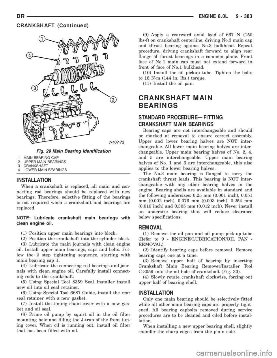
Bearing caps are not interchangeable and should
be marked at removal to ensure correct assembly.
Upper and lower bearing halves are NOT inter-
changeable. All lower main bearing halves are inter-
changeable. Upper main bearing halves of No. 2, 4,
and 5 are interchangeable. Upper main bearing
halves of No. 1 and 6 are interchangeable, this also
applies to the lower bearing halves.
The No.3 main bearing is flanged to carry the
crankshaft thrust loads. This bearing is NOT inter-
changeable with any other bearing halves in the
engine. Bearing shells are available in standard and
the following undersizes: 0.25 mm (0.001 inch), 0.051
mm (0.002 inch), 0.076 mm (0.003 inch), 0.254 mm
(0.010 inch) and 0.305 mm (0.012 inch). Never install
an undersize bearing that will reduce clearance
below specifications.
REMOVAL
(1) Remove the oil pan and oil pump pick-up tube
(Refer to 9 - ENGINE/LUBRICATION/OIL PAN -
REMOVAL).
(2) Identify bearing caps before removal. Remove
bearing caps one at a time.
(3) Remove upper half of bearing by inserting
Crankshaft Main Bearing Remover/Installer Tool
C-3059 into the oil hole of crankshaft (Fig. 30).
(4) Slowly rotate crankshaft clockwise, forcing out
upper half of bearing shell.
INSTALLATION
Only one main bearing should be selectively fitted
while all other main bearing caps are properly tight-
ened. All bearing capbolts removed during service
procedures are to be cleaned and oiled before instal-
lation.
When installing a new upper bearing shell, slightly
chamfer the sharp edges from the plain side.
Fig. 29 Main Bearing Identification
1 - MAIN BEARING CAP
2 - UPPER MAIN BEARINGS
3 - CRANKSHAFT
4 - LOWER MAIN BEARINGS
DRENGINE 8.0L 9 - 383
CRANKSHAFT (Continued)