2003 DODGE RAM light
[x] Cancel search: lightPage 1482 of 2895
(1) Perform the Fuel Pressure Release Procedure
(Refer to 14 - FUEL SYSTEM/FUEL DELIVERY -
STANDARD PROCEDURE).
(2) Disconnect the negative cable(s) from the bat-
tery.
(3) Inspect air cleaner, induction system, and
intake manifold to ensure system is dry and clear of
foreign material.
(4) Place a shop towel around the spark plugs to
catch any fluid that may possibly be under pressure
in the cylinder head. Remove the spark plugs.
(5) With all spark plugs removed, rotate the crank-
shaft using a breaker bar and socket.
(6) Identify the fluid in the cylinders (coolant, fuel,
oil, etc.).
(7) Be sure all fluid has been removed from the
cylinders.
(8) Repair engine or components as necessary to
prevent this problem from occurring again.
(9) Squirt a small amount of engine oil into the
cylinders to lubricate the walls. This will prevent
damage on restart.
(10) Install new spark plugs. Tighten the spark
plugs to 41 N´m (30 ft. lbs.) torque.
(11) Drain engine oil. Remove and discard the oil
filter.
(12) Install the drain plug. Tighten the plug to 34
N´m (25 ft. lbs.) torque.
(13) Install a new oil filter.
(14) Fill engine crankcase with the specified
amount and grade of oil. (Refer to LUBRICATION &
MAINTENANCE - SPECIFICATIONS).
(15) Connect the negative cable(s) to the battery.
(16) Start the engine and check for any leaks.
STANDARD PROCEDURE - CYLINDER BORE
HONING
Before honing, stuff plenty of clean shop towels
under the bores and over the crankshaft to keep
abrasive materials from entering the crankshaft
area.
(1) Used carefully, the Cylinder Bore Sizing Hone
C-823, equipped with 220 grit stones, is the best tool
for this job. In addition to deglazing, it will reduce
taper and out-of-round, as well as removing light
scuffing, scoring and scratches. Usually, a few strokes
will clean up a bore and maintain the required lim-
its.
CAUTION: DO NOT use rigid type hones to remove
cylinder wall glaze.
(2) Deglazing of the cylinder walls may be done if
the cylinder bore is straight and round. Use a cylin-
der surfacing hone, Honing Tool C-3501, equipped
with 280 grit stones (C-3501-3810). about 20-60strokes, depending on the bore condition, will be suf-
ficient to provide a satisfactory surface. Using honing
oil C-3501-3880, or a light honing oil, available from
major oil distributors.
CAUTION: DO NOT use engine or transmission oil,
mineral spirits, or kerosene.
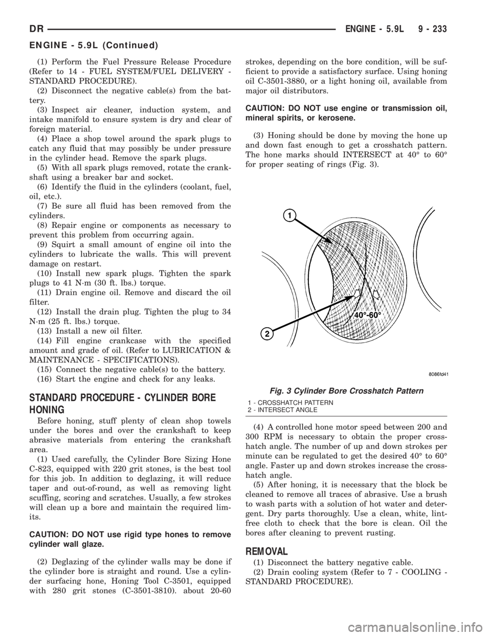
(3) Honing should be done by moving the hone up
and down fast enough to get a crosshatch pattern.
The hone marks should INTERSECT at 40É to 60É
for proper seating of rings (Fig. 3).
(4) A controlled hone motor speed between 200 and
300 RPM is necessary to obtain the proper cross-
hatch angle. The number of up and down strokes per
minute can be regulated to get the desired 40É to 60É
angle. Faster up and down strokes increase the cross-
hatch angle.
(5) After honing, it is necessary that the block be
cleaned to remove all traces of abrasive. Use a brush
to wash parts with a solution of hot water and deter-
gent. Dry parts thoroughly. Use a clean, white, lint-
free cloth to check that the bore is clean. Oil the
bores after cleaning to prevent rusting.
REMOVAL
(1) Disconnect the battery negative cable.
(2) Drain cooling system (Refer to 7 - COOLING -
STANDARD PROCEDURE).
Fig. 3 Cylinder Bore Crosshatch Pattern
1 - CROSSHATCH PATTERN
2 - INTERSECT ANGLE
DRENGINE - 5.9L 9 - 233
ENGINE - 5.9L (Continued)
Page 1493 of 2895
If a large combustion/compression pressure leak
exists, bubbles will be visible in the coolant.
COOLING SYSTEM TESTER METHOD
WARNING: WITH COOLING SYSTEM TESTER IN
PLACE, PRESSURE WILL BUILD UP FAST. EXCES-
SIVE PRESSURE BUILT UP, BY CONTINUOUS
ENGINE OPERATION, MUST BE RELEASED TO A
SAFE PRESSURE POINT. NEVER PERMIT PRES-
SURE TO EXCEED 138 kPa (20 psi).
Install Cooling System Tester 7700 or equivalent to
pressure cap neck. Start the engine and observe the
tester's pressure gauge. If gauge pulsates with every
power stroke of a cylinder a combustion pressure
leak is evident.
CHEMICAL TEST METHOD
Combustion leaks into the cooling system can also
be checked by using Bloc-Chek Kit C-3685-A or
equivalent. Perform test following the procedures
supplied with the tool kit.
REMOVAL
(1) Disconnect the battery negative cable.
(2) Drain cooling system (Refer to 7 - COOLING -
STANDARD PROCEDURE).
(3) Remove the air cleaner resonator and duct
work.
(4) Remove the intake manifold-to-generator
bracket support rod. Remove the generator.
(5) Remove closed crankcase ventilation system.
(6) Disconnect the evaporation control system.
(7) Perform the Fuel System Pressure Release pro-
cedure (Refer to 14 - FUEL SYSTEM/FUEL DELIV-
ERY - STANDARD PROCEDURE). Disconnect the
fuel supply line (Refer to 14 - FUEL SYSTEM/FUEL
DELIVERY/QUICK CONNECT FITTING - STAN-
DARD PROCEDURE).
(8) Disconnect accelerator linkage and if so
equipped, the speed control and transmission kick-
down cables.
(9) Remove distributor cap and wires.
(10) Disconnect the coil wires.
(11) Disconnect heat indicator sending unit wire.
(12) Disconnect heater hoses and bypass hose.
(13) Remove the master cylinder and booster
assembly. Refer to section 5 brakes.
(14) Remove cylinder head covers and gaskets
(Refer to 9 - ENGINE/CYLINDER HEAD/CYLIN-
DER HEAD COVER(S) - REMOVAL).
(15) Remove intake manifold (Refer to 9 -
ENGINE/MANIFOLDS/INTAKE MANIFOLD -
REMOVAL) and throttle body as an assembly. Dis-
card the flange side gaskets and the front and rear
cross-over gaskets.(16) Remove exhaust manifolds (Refer to 9 -
ENGINE/MANIFOLDS/EXHAUST MANIFOLD -
REMOVAL).
(17) Remove rocker arm assemblies and push rods.
Identify to ensure installation in original locations.
(18) Remove the head bolts from each cylinder
head and remove cylinder heads. Discard the cylin-
der head gasket.
(19) Remove spark plugs.
CLEANING
Clean all surfaces of cylinder block and cylinder
heads.
Clean cylinder block front and rear gasket surfaces
using a suitable solvent.
INSPECTION
Inspect all surfaces with a straightedge if there is
any reason to suspect leakage. If out-of-flatness
exceeds 0.00075mm/mm (0.0001in/in.) times the span
length in any direction, either replace head or lightly
machine the head surface.
FOR EXAMPLE:ÐA 305 mm (12 in.) span is
0.102 mm (0.004 in.) out-of-flat. The allowable out-of-
flat is 305 x 0.00075 (12 x 0.00075) equals 0.23 mm
(0.009 in.). This amount of out-of-flat is acceptable.
The cylinder head surface finish should be
1.78-3.00 microns (70-125 microinches).
Inspect push rods. Replace worn or bent rods.
INSTALLATION
(1) Clean all surfaces of cylinder block and cylin-
der heads.
(2) Clean cylinder block front and rear gasket sur-
faces using a suitable solvent.
(3) Position new cylinder head gaskets onto the
cylinder block.
(4) Position cylinder heads onto head gaskets and
cylinder block.
(5) Starting at top center, tighten all cylinder head
bolts, in sequence (Fig. 8).
CAUTION: When tightening the rocker arm bolts,
make sure the piston in that cylinder is NOT at
TDC. Contact between the valves and piston could
occur.
(6) Install push rods and rocker arm assemblies in
their original position. Tighten the bolts to 28 N´m
(21 ft. lbs.) torque.
(7) Install the intake manifold (Refer to 9 -
ENGINE/MANIFOLDS/INTAKE MANIFOLD -
INSTALLATION) and throttle body assembly.
(8) Install exhaust manifolds (Refer to 9 -
ENGINE/MANIFOLDS/EXHAUST MANIFOLD -
INSTALLATION).
9 - 244 ENGINE - 5.9LDR
CYLINDER HEAD (Continued)
Page 1497 of 2895
ing stones. A true and complete surface must be
obtained.
(2) Measure the concentricity of valve seat using a
dial indicator. Total runout should not exceed 0.051
mm (0.002 in.) total indicator reading.
(3) Inspect the valve seat with Prussian blue, to
determine where the valve contacts the seat. To do
this, coat valve seat LIGHTLY with Prussian blue
then set valve in place. Rotate the valve with light
pressure. If the blue is transferred to the center of
valve face, contact is satisfactory. If the blue is trans-
ferred to the top edge of valve face, lower valve seat
with a 15É stone. If the blue is transferred to bottom
edge of valve face raise valve seat with a 60É stone.
(4) When seat is properly positioned the width of
intake seats should be 1.016-1.524 mm (0.040-0.060
in.). The width of the exhaust seats should be 1.524-
2.032 mm (0.060-0.080 in.).
VALVE SPRINGS
Whenever valves have been removed for inspection,
reconditioning or replacement, valve springs should
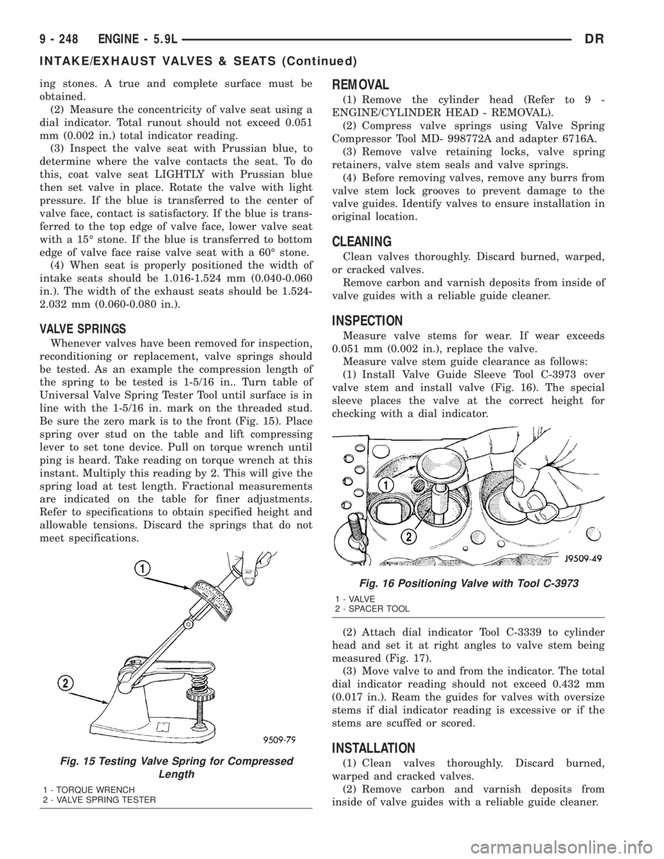
be tested. As an example the compression length of
the spring to be tested is 1-5/16 in.. Turn table of
Universal Valve Spring Tester Tool until surface is in
line with the 1-5/16 in. mark on the threaded stud.
Be sure the zero mark is to the front (Fig. 15). Place
spring over stud on the table and lift compressing
lever to set tone device. Pull on torque wrench until
ping is heard. Take reading on torque wrench at this
instant. Multiply this reading by 2. This will give the
spring load at test length. Fractional measurements
are indicated on the table for finer adjustments.
Refer to specifications to obtain specified height and
allowable tensions. Discard the springs that do not
meet specifications.
REMOVAL
(1) Remove the cylinder head (Refer to 9 -
ENGINE/CYLINDER HEAD - REMOVAL).
(2) Compress valve springs using Valve Spring
Compressor Tool MD- 998772A and adapter 6716A.
(3) Remove valve retaining locks, valve spring
retainers, valve stem seals and valve springs.
(4) Before removing valves, remove any burrs from
valve stem lock grooves to prevent damage to the
valve guides. Identify valves to ensure installation in
original location.
CLEANING
Clean valves thoroughly. Discard burned, warped,
or cracked valves.
Remove carbon and varnish deposits from inside of
valve guides with a reliable guide cleaner.
INSPECTION
Measure valve stems for wear. If wear exceeds
0.051 mm (0.002 in.), replace the valve.
Measure valve stem guide clearance as follows:
(1) Install Valve Guide Sleeve Tool C-3973 over
valve stem and install valve (Fig. 16). The special
sleeve places the valve at the correct height for
checking with a dial indicator.
(2) Attach dial indicator Tool C-3339 to cylinder
head and set it at right angles to valve stem being
measured (Fig. 17).
(3) Move valve to and from the indicator. The total
dial indicator reading should not exceed 0.432 mm
(0.017 in.). Ream the guides for valves with oversize
stems if dial indicator reading is excessive or if the
stems are scuffed or scored.
INSTALLATION
(1) Clean valves thoroughly. Discard burned,
warped and cracked valves.
(2) Remove carbon and varnish deposits from
inside of valve guides with a reliable guide cleaner.Fig. 15 Testing Valve Spring for Compressed
Length
1 - TORQUE WRENCH
2 - VALVE SPRING TESTER
Fig. 16 Positioning Valve with Tool C-3973
1 - VALVE
2 - SPACER TOOL
9 - 248 ENGINE - 5.9LDR
INTAKE/EXHAUST VALVES & SEATS (Continued)
Page 1501 of 2895
CRANKSHAFT
DESCRIPTION
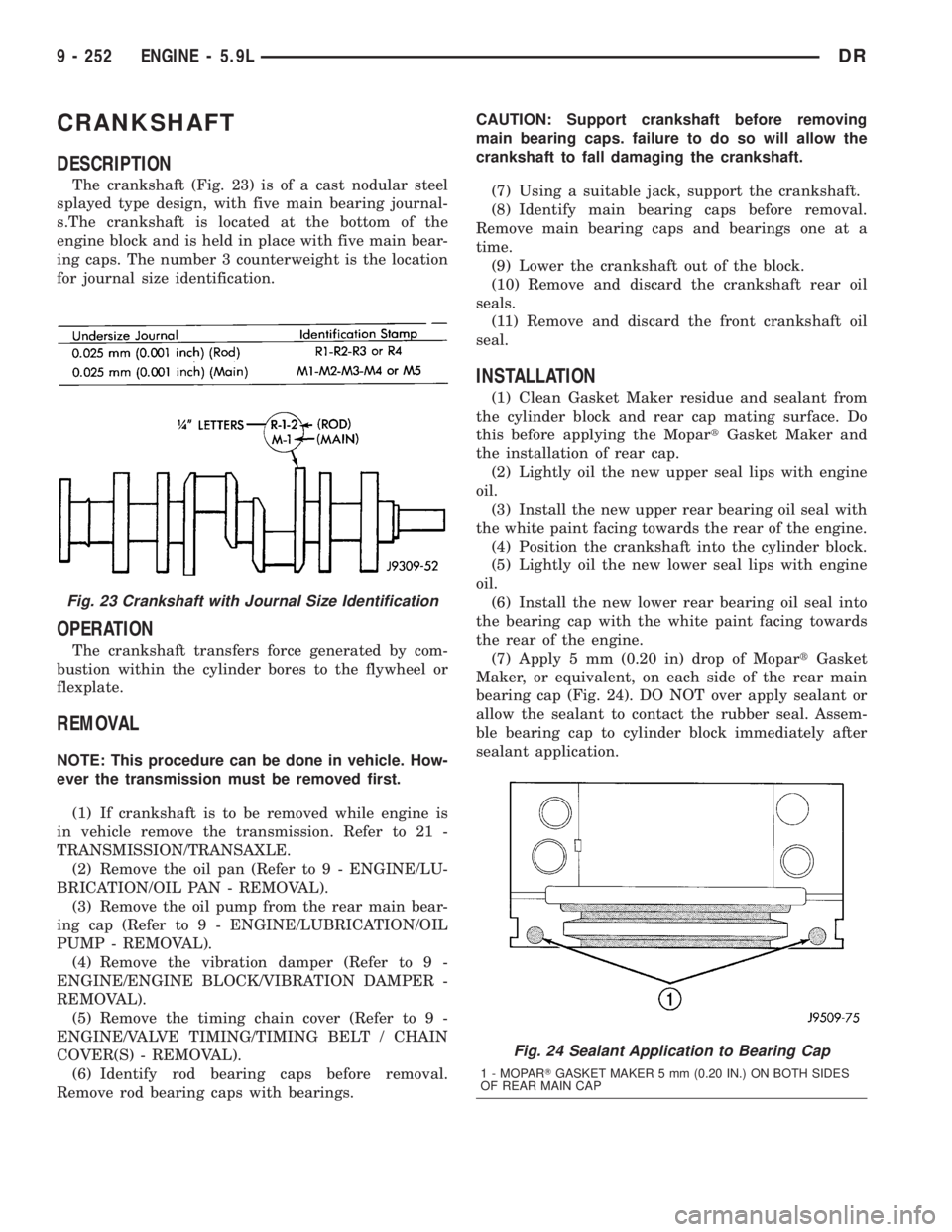
The crankshaft (Fig. 23) is of a cast nodular steel
splayed type design, with five main bearing journal-
s.The crankshaft is located at the bottom of the
engine block and is held in place with five main bear-
ing caps. The number 3 counterweight is the location
for journal size identification.
OPERATION
The crankshaft transfers force generated by com-
bustion within the cylinder bores to the flywheel or
flexplate.
REMOVAL
NOTE: This procedure can be done in vehicle. How-
ever the transmission must be removed first.
(1) If crankshaft is to be removed while engine is
in vehicle remove the transmission. Refer to 21 -
TRANSMISSION/TRANSAXLE.
(2) Remove the oil pan (Refer to 9 - ENGINE/LU-
BRICATION/OIL PAN - REMOVAL).
(3) Remove the oil pump from the rear main bear-
ing cap (Refer to 9 - ENGINE/LUBRICATION/OIL
PUMP - REMOVAL).
(4) Remove the vibration damper (Refer to 9 -
ENGINE/ENGINE BLOCK/VIBRATION DAMPER -
REMOVAL).
(5) Remove the timing chain cover (Refer to 9 -
ENGINE/VALVE TIMING/TIMING BELT / CHAIN
COVER(S) - REMOVAL).
(6) Identify rod bearing caps before removal.
Remove rod bearing caps with bearings.CAUTION: Support crankshaft before removing
main bearing caps. failure to do so will allow the
crankshaft to fall damaging the crankshaft.
(7) Using a suitable jack, support the crankshaft.
(8) Identify main bearing caps before removal.
Remove main bearing caps and bearings one at a
time.
(9) Lower the crankshaft out of the block.
(10) Remove and discard the crankshaft rear oil
seals.
(11) Remove and discard the front crankshaft oil
seal.
INSTALLATION
(1) Clean Gasket Maker residue and sealant from
the cylinder block and rear cap mating surface. Do
this before applying the MopartGasket Maker and
the installation of rear cap.
(2) Lightly oil the new upper seal lips with engine
oil.
(3) Install the new upper rear bearing oil seal with
the white paint facing towards the rear of the engine.
(4) Position the crankshaft into the cylinder block.
(5) Lightly oil the new lower seal lips with engine
oil.
(6) Install the new lower rear bearing oil seal into
the bearing cap with the white paint facing towards
the rear of the engine.
(7) Apply 5 mm (0.20 in) drop of MopartGasket
Maker, or equivalent, on each side of the rear main
bearing cap (Fig. 24). DO NOT over apply sealant or
allow the sealant to contact the rubber seal. Assem-
ble bearing cap to cylinder block immediately after
sealant application.
Fig. 23 Crankshaft with Journal Size Identification
Fig. 24 Sealant Application to Bearing Cap
1 - MOPARTGASKET MAKER 5 mm (0.20 IN.) ON BOTH SIDES
OF REAR MAIN CAP
9 - 252 ENGINE - 5.9LDR
Page 1503 of 2895
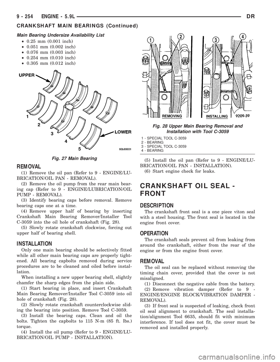
Main Bearing Undersize Availability List
²0.25 mm (0.001 inch)
²0.051 mm (0.002 inch)
²0.076 mm (0.003 inch)
²0.254 mm (0.010 inch)
²0.305 mm (0.012 inch)
REMOVAL
(1) Remove the oil pan (Refer to 9 - ENGINE/LU-
BRICATION/OIL PAN - REMOVAL).
(2) Remove the oil pump from the rear main bear-
ing cap (Refer to 9 - ENGINE/LUBRICATION/OIL
PUMP - REMOVAL).
(3) Identify bearing caps before removal. Remove
bearing caps one at a time.
(4) Remove upper half of bearing by inserting
Crankshaft Main Bearing Remover/Installer Tool
C-3059 into the oil hole of crankshaft (Fig. 28).
(5) Slowly rotate crankshaft clockwise, forcing out
upper half of bearing shell.
INSTALLATION
Only one main bearing should be selectively fitted
while all other main bearing caps are properly tight-
ened. All bearing capbolts removed during service
procedures are to be cleaned and oiled before instal-
lation.
When installing a new upper bearing shell, slightly
chamfer the sharp edges from the plain side.
(1) Start bearing in place, and insert Crankshaft
Main Bearing Remover/Installer Tool C-3059 into oil
hole of crankshaft (Fig. 28).
(2) Slowly rotate crankshaft counterclockwise slid-
ing the bearing into position. Remove Tool C-3059.
(3) Install the bearing caps. Clean and oil the
bolts. Tighten the capbolts to 115 N´m (85 ft. lbs.)
torque.
(4) Install the oil pump (Refer to 9 - ENGINE/LU-
BRICATION/OIL PUMP - INSTALLATION).(5) Install the oil pan (Refer to 9 - ENGINE/LU-
BRICATION/OIL PAN - INSTALLATION).
(6) Start engine check for leaks.
CRANKSHAFT OIL SEAL -
FRONT
DESCRIPTION
The crankshaft front seal is a one piece viton seal
with a steel housing. The front seal is located in the
engine front cover.
OPERATION
The crankshaft seals prevent oil from leaking from
around the crankshaft, either from the rear of the
engine or from the engine front cover.
REMOVAL
The oil seal can be replaced without removing the
timing chain cover, provided that the cover is not
misaligned.
(1) Disconnect the negative cable from the battery.
(2) Remove vibration damper (Refer to 9 -
ENGINE/ENGINE BLOCK/VIBRATION DAMPER -
REMOVAL).
(3) If front seal is suspected of leaking, check front
oil seal alignment to crankshaft. The seal installa-
tion/alignment Tool 6635, should fit with minimum
interference. If tool does not fit, the cover must be
removed and installed properly.
Fig. 27 Main Bearing
Fig. 28 Upper Main Bearing Removal and
Installation with Tool C-3059
1 - SPECIAL TOOL C-3059
2 - BEARING
3 - SPECIAL TOOL C-3059
4 - BEARING
9 - 254 ENGINE - 5.9LDR
CRANKSHAFT MAIN BEARINGS (Continued)
Page 1505 of 2895
lower seal. The lower seal half can be installed only
with the rear main bearing cap removed.
UPPER SEAL ÐCRANKSHAFT REMOVED
(1) Remove the crankshaft (Refer to 9 - ENGINE/
ENGINE BLOCK/CRANKSHAFT - REMOVAL). Dis-
card the old upper seal.
UPPER SEALÐCRANKSHAFT INSTALLED
(1) Remove the oil pan (Refer to 9 - ENGINE/LU-
BRICATION/OIL PAN - REMOVAL).
(2) Remove the oil pump (Refer to 9 - ENGINE/
LUBRICATION/OIL PUMP - REMOVAL).
(3) Remove the rear main bearing cap. Remove
and discard the old lower oil seal.
(4) Carefully remove and discard the old upper oil
seal.
LOWER SEAL
(1) Remove the oil pan (Refer to 9 - ENGINE/LU-
BRICATION/OIL PAN - REMOVAL).
(2) Remove the oil pump (Refer to 9 - ENGINE/
LUBRICATION/OIL PUMP - REMOVAL).
(3) Remove the rear main bearing cap and discard
the old lower seal.
INSTALLATION
The service seal is a two piece, Viton seal. The
upper seal half can be installed with crankshaft
removed from engine or with crankshaft installed.
When a new upper seal is installed, install a new
lower seal. The lower seal half can be installed only
with the rear main bearing cap removed.
UPPER SEAL ÐCRANKSHAFT REMOVED
(1) Clean the cylinder block rear cap mating sur-
face. Be sure the seal groove is free of debris. Check
for burrs at the oil hole on the cylinder block mating
surface to rear cap.
(2) Lightly oil the new upper seal lips with engine
oil.
(3) Install the new upper rear bearing oil seal with
the white paint facing toward the rear of the engine.
(4) Position the crankshaft into the cylinder block.
(5)
Lightly oil the new lower seal lips with engine oil.
(6) Install the new lower rear bearing oil seal into
the bearing cap with the white paint facing towards
the rear of the engine.
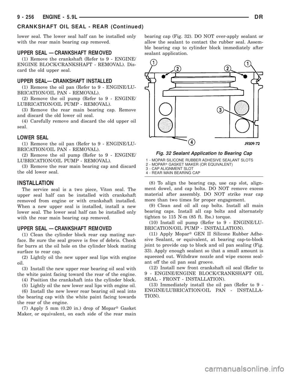
(7) Apply 5 mm (0.20 in.) drop of MopartGasket
Maker, or equivalent, on each side of the rear mainbearing cap (Fig. 32). DO NOT over-apply sealant or
allow the sealant to contact the rubber seal. Assem-
ble bearing cap to cylinder block immediately after
sealant application.
(8) To align the bearing cap, use cap slot, align-
ment dowel, and cap bolts. DO NOT remove excess
material after assembly. DO NOT strike rear cap
more than two times for proper engagement.
(9) Clean and oil all cap bolts. Install all main
bearing caps. Install all cap bolts and alternately
tighten to 115 N´m (85 ft. lbs.) torque.
(10) Install oil pump (Refer to 9 - ENGINE/LU-
BRICATION/OIL PUMP - INSTALLATION).
(11) Apply MopartGEN II Silicone Rubber Adhe-
sive Sealant, or equivalent, at bearing cap-to-block
joint to provide cap to block and oil pan sealing (Fig.
33). Apply enough sealant so that a small amount is
squeezed out. Withdraw nozzle and wipe excess seal-
ant off the oil pan seal groove.
(12) Install new front crankshaft oil seal (Refer to
9 - ENGINE/ENGINE BLOCK/CRANKSHAFT OIL
SEAL - FRONT - INSTALLATION).
(13) Immediately install the oil pan (Refer to 9 -
ENGINE/LUBRICATION/OIL PAN - INSTALLA-
TION).
Fig. 32 Sealant Application to Bearing Cap
1 - MOPAR SILICONE RUBBER ADHESIVE SEALANT SLOTS
2 - MOPARTGASKET MAKER (OR EQUIVALENT)
3 - CAP ALIGNMENT SLOT
4 - REAR MAIN BEARING CAP
9 - 256 ENGINE - 5.9LDR
CRANKSHAFT OIL SEAL - REAR (Continued)
Page 1506 of 2895
UPPER SEALÐCRANKSHAFT INSTALLED
(1) Clean the cylinder block mating surfaces before
oil seal installation. Check for burrs at the oil hole on
the cylinder block mating surface to rear cap.
(2) Lightly oil the new upper seal lips with engine
oil. To allow ease of installation of the seal, loosen at
least the two main bearing caps forward of the rear
bearing cap.
(3) Rotate the new upper seal into the cylinder
block, being careful not to shave or cut the outer sur-
face of the seal. To ensure proper installation, use the
installation tool provided with the kit. Install the
new seal with the white paint facing toward the rear
of the engine.
(4) Install the new lower rear bearing oil seal into
the bearing cap with the white paint facing toward
the rear of the engine.
(5) Apply 5 mm (0.20 in.) drop of MopartGasket
Maker, or equivalent, on each side of the rear main
bearing cap (Fig. 32). DO NOT over-apply sealant or
allow the sealant to contact the rubber seal. Assem-
ble bearing cap to cylinder block immediately after
sealant application. Be sure the white paint faces
toward the rear of the engine.
(6) To align the bearing cap, use cap slot, align-
ment dowel, and cap bolts. DO NOT remove excess
material after assembly. DO NOT strike rear cap
more than two times for proper engagement.(7) Install the rear main bearing cap with cleaned
and oiled cap bolts. Alternately tighten ALL cap bolts
to 115 N´m (85 ft. lbs.) torque.
(8) Install oil pump (Refer to 9 - ENGINE/LUBRI-
CATION/OIL PUMP - INSTALLATION).
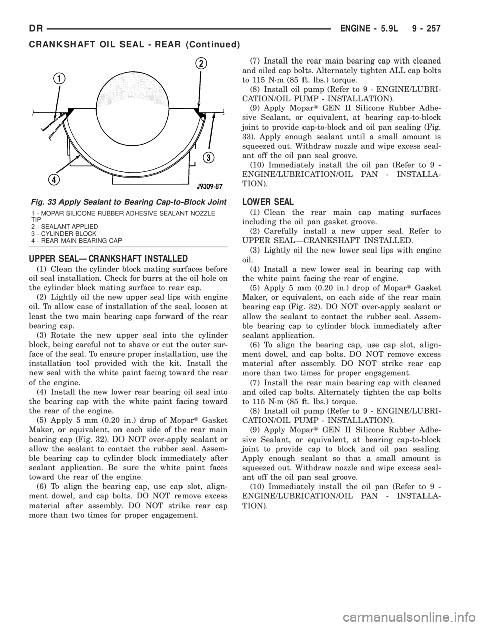
(9) Apply MopartGEN II Silicone Rubber Adhe-
sive Sealant, or equivalent, at bearing cap-to-block
joint to provide cap-to-block and oil pan sealing (Fig.
33). Apply enough sealant until a small amount is
squeezed out. Withdraw nozzle and wipe excess seal-
ant off the oil pan seal groove.
(10) Immediately install the oil pan (Refer to 9 -
ENGINE/LUBRICATION/OIL PAN - INSTALLA-
TION).
LOWER SEAL
(1) Clean the rear main cap mating surfaces
including the oil pan gasket groove.
(2) Carefully install a new upper seal. Refer to
UPPER SEALÐCRANKSHAFT INSTALLED.
(3) Lightly oil the new lower seal lips with engine
oil.
(4) Install a new lower seal in bearing cap with
the white paint facing the rear of engine.
(5) Apply 5 mm (0.20 in.) drop of MopartGasket
Maker, or equivalent, on each side of the rear main
bearing cap (Fig. 32). DO NOT over-apply sealant or
allow the sealant to contact the rubber seal. Assem-
ble bearing cap to cylinder block immediately after
sealant application.
(6) To align the bearing cap, use cap slot, align-
ment dowel, and cap bolts. DO NOT remove excess
material after assembly. DO NOT strike rear cap
more than two times for proper engagement.
(7) Install the rear main bearing cap with cleaned
and oiled cap bolts. Alternately tighten the cap bolts
to 115 N´m (85 ft. lbs.) torque.
(8) Install oil pump (Refer to 9 - ENGINE/LUBRI-
CATION/OIL PUMP - INSTALLATION).
(9) Apply MopartGEN II Silicone Rubber Adhe-
sive Sealant, or equivalent, at bearing cap-to-block
joint to provide cap to block and oil pan sealing.
Apply enough sealant so that a small amount is
squeezed out. Withdraw nozzle and wipe excess seal-
ant off the oil pan seal groove.
(10) Immediately install the oil pan (Refer to 9 -
ENGINE/LUBRICATION/OIL PAN - INSTALLA-
TION).
Fig. 33 Apply Sealant to Bearing Cap-to-Block Joint
1 - MOPAR SILICONE RUBBER ADHESIVE SEALANT NOZZLE
TIP
2 - SEALANT APPLIED
3 - CYLINDER BLOCK
4 - REAR MAIN BEARING CAP
DRENGINE - 5.9L 9 - 257
CRANKSHAFT OIL SEAL - REAR (Continued)
Page 1508 of 2895
intake side of oil pump through which air can be
drawn will create the same tappet action. Check the
lubrication system from the intake strainer to the
pump cover, including the relief valve retainer cap.
When tappet noise is due to aeration, it may be
intermittent or constant, and usually more than one
tappet will be noisy. When oil level and leaks have
been corrected, operate the engine at fast idle. Run
engine for a sufficient time to allow all of the air
inside the tappets to be bled out.
TAPPET NOISE DIAGNOSIS
(1) To determine source of tappet noise, operate
engine at idle with cylinder head covers removed.
(2) Feel each valve spring or rocker arm to detect
noisy tappet. The noisy tappet will cause the affected
spring and/or rocker arm to vibrate or feel rough in
operation.
NOTE: Worn valve guides or cocked springs are
sometimes mistaken for noisy tappets. If such is
the case, noise may be dampened by applying side
thrust on the valve spring. If noise is not apprecia-
bly reduced, it can be assumed the noise is in the
tappet. Inspect the rocker arm push rod sockets
and push rod ends for wear.
(3) Valve tappet noise ranges from light noise to a
heavy click. A light noise is usually caused by exces-
sive leak-down around the unit plunger, or by the
plunger partially sticking in the tappet body cylinder.
The tappet should be replaced. A heavy click is
caused by a tappet check valve not seating, or by for-
eign particles wedged between the plunger and the
tappet body. This will cause the plunger to stick in
the down position. This heavy click will be accompa-
nied by excessive clearance between the valve stem
and rocker arm as valve closes. In either case, tappet
assembly should be removed for inspection and clean-
ing.
(4) The valve train generates a noise very much
like a light tappet noise during normal operation.
Care must be taken to ensure that tappets are mak-
ing the noise. If more than one tappet seems to be
noisy, it's probably not the tappets.
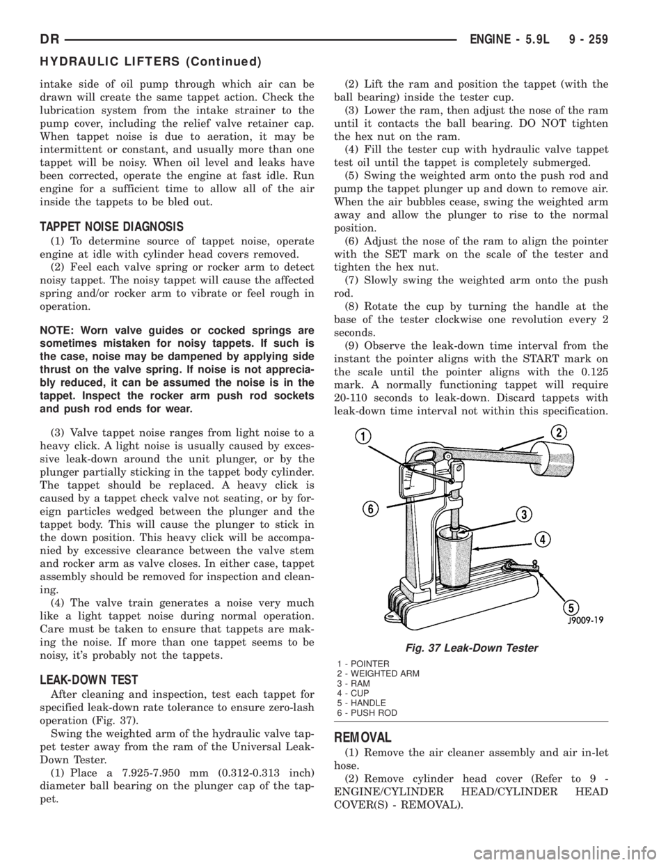
LEAK-DOWN TEST
After cleaning and inspection, test each tappet for
specified leak-down rate tolerance to ensure zero-lash
operation (Fig. 37).
Swing the weighted arm of the hydraulic valve tap-
pet tester away from the ram of the Universal Leak-
Down Tester.
(1) Place a 7.925-7.950 mm (0.312-0.313 inch)
diameter ball bearing on the plunger cap of the tap-
pet.(2) Lift the ram and position the tappet (with the
ball bearing) inside the tester cup.
(3) Lower the ram, then adjust the nose of the ram
until it contacts the ball bearing. DO NOT tighten
the hex nut on the ram.
(4) Fill the tester cup with hydraulic valve tappet
test oil until the tappet is completely submerged.
(5) Swing the weighted arm onto the push rod and
pump the tappet plunger up and down to remove air.
When the air bubbles cease, swing the weighted arm
away and allow the plunger to rise to the normal
position.
(6) Adjust the nose of the ram to align the pointer
with the SET mark on the scale of the tester and
tighten the hex nut.
(7) Slowly swing the weighted arm onto the push
rod.
(8) Rotate the cup by turning the handle at the
base of the tester clockwise one revolution every 2
seconds.
(9) Observe the leak-down time interval from the
instant the pointer aligns with the START mark on
the scale until the pointer aligns with the 0.125
mark. A normally functioning tappet will require
20-110 seconds to leak-down. Discard tappets with
leak-down time interval not within this specification.
REMOVAL
(1) Remove the air cleaner assembly and air in-let
hose.
(2) Remove cylinder head cover (Refer to 9 -
ENGINE/CYLINDER HEAD/CYLINDER HEAD
COVER(S) - REMOVAL).
Fig. 37 Leak-Down Tester
1 - POINTER
2 - WEIGHTED ARM
3 - RAM
4 - CUP
5 - HANDLE
6 - PUSH ROD
DRENGINE - 5.9L 9 - 259
HYDRAULIC LIFTERS (Continued)