2003 DODGE RAM light
[x] Cancel search: lightPage 1399 of 2895
DIAGNOSIS AND TESTING
DIAGNOSIS AND TESTING - CHECKING
ENGINE OIL PRESSURE
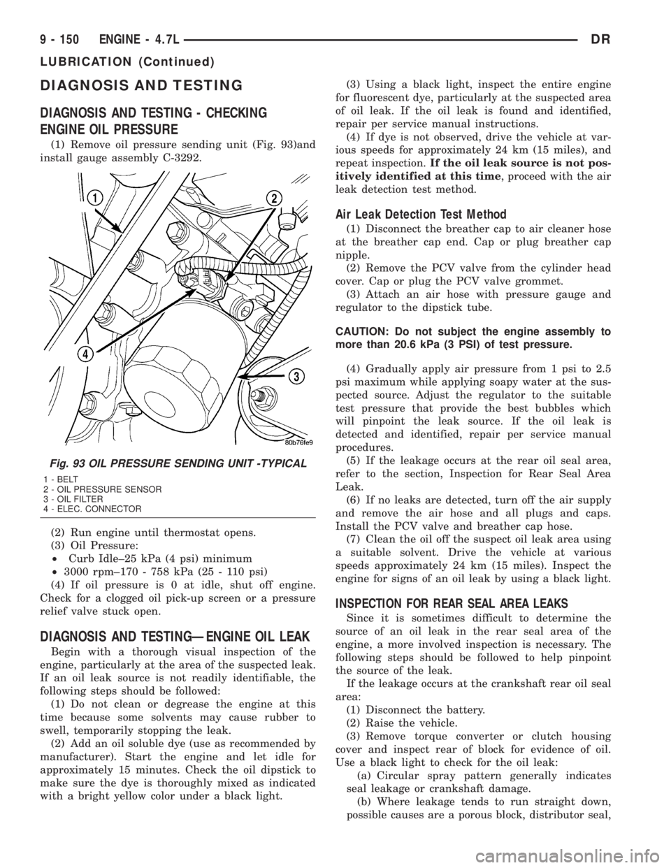
(1) Remove oil pressure sending unit (Fig. 93)and
install gauge assembly C-3292.
(2) Run engine until thermostat opens.
(3) Oil Pressure:
²Curb Idle±25 kPa (4 psi) minimum
²3000 rpm±170 - 758 kPa (25 - 110 psi)
(4) If oil pressure is 0 at idle, shut off engine.
Check for a clogged oil pick-up screen or a pressure
relief valve stuck open.
DIAGNOSIS AND TESTINGÐENGINE OIL LEAK
Begin with a thorough visual inspection of the
engine, particularly at the area of the suspected leak.
If an oil leak source is not readily identifiable, the
following steps should be followed:
(1) Do not clean or degrease the engine at this
time because some solvents may cause rubber to
swell, temporarily stopping the leak.
(2) Add an oil soluble dye (use as recommended by
manufacturer). Start the engine and let idle for
approximately 15 minutes. Check the oil dipstick to
make sure the dye is thoroughly mixed as indicated
with a bright yellow color under a black light.(3) Using a black light, inspect the entire engine
for fluorescent dye, particularly at the suspected area
of oil leak. If the oil leak is found and identified,
repair per service manual instructions.
(4) If dye is not observed, drive the vehicle at var-
ious speeds for approximately 24 km (15 miles), and
repeat inspection.If the oil leak source is not pos-
itively identified at this time, proceed with the air
leak detection test method.
Air Leak Detection Test Method
(1) Disconnect the breather cap to air cleaner hose
at the breather cap end. Cap or plug breather cap
nipple.
(2) Remove the PCV valve from the cylinder head
cover. Cap or plug the PCV valve grommet.
(3) Attach an air hose with pressure gauge and
regulator to the dipstick tube.
CAUTION: Do not subject the engine assembly to
more than 20.6 kPa (3 PSI) of test pressure.
(4) Gradually apply air pressure from 1 psi to 2.5
psi maximum while applying soapy water at the sus-
pected source. Adjust the regulator to the suitable
test pressure that provide the best bubbles which
will pinpoint the leak source. If the oil leak is
detected and identified, repair per service manual
procedures.
(5) If the leakage occurs at the rear oil seal area,
refer to the section, Inspection for Rear Seal Area
Leak.
(6) If no leaks are detected, turn off the air supply
and remove the air hose and all plugs and caps.
Install the PCV valve and breather cap hose.
(7) Clean the oil off the suspect oil leak area using
a suitable solvent. Drive the vehicle at various
speeds approximately 24 km (15 miles). Inspect the
engine for signs of an oil leak by using a black light.
INSPECTION FOR REAR SEAL AREA LEAKS
Since it is sometimes difficult to determine the
source of an oil leak in the rear seal area of the
engine, a more involved inspection is necessary. The
following steps should be followed to help pinpoint
the source of the leak.
If the leakage occurs at the crankshaft rear oil seal
area:
(1) Disconnect the battery.
(2) Raise the vehicle.
(3) Remove torque converter or clutch housing
cover and inspect rear of block for evidence of oil.
Use a black light to check for the oil leak:
(a) Circular spray pattern generally indicates
seal leakage or crankshaft damage.
(b) Where leakage tends to run straight down,
possible causes are a porous block, distributor seal,
Fig. 93 OIL PRESSURE SENDING UNIT -TYPICAL
1 - BELT
2 - OIL PRESSURE SENSOR
3 - OIL FILTER
4 - ELEC. CONNECTOR
9 - 150 ENGINE - 4.7LDR
LUBRICATION (Continued)
Page 1402 of 2895
(4) When filter separates from cylinder block oil
filter boss, tip gasket end upward to minimize oil
spill. Remove filter from vehicle.
NOTE: Make sure filter gasket was removed with fil-
ter.
(5) With a wiping cloth, clean the gasket sealing
surface of oil and grime.
INSTALLATION
(1) Lightly lubricate oil filter gasket with engine
oil.
(2) Thread filter onto adapter nipple. When gasket
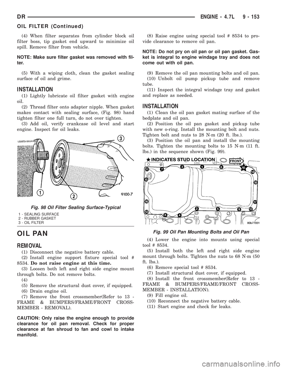
makes contact with sealing surface, (Fig. 98) hand
tighten filter one full turn, do not over tighten.
(3) Add oil, verify crankcase oil level and start
engine. Inspect for oil leaks.
OIL PAN
REMOVAL
(1) Disconnect the negative battery cable.
(2) Install engine support fixture special tool #
8534.Do not raise engine at this time.
(3) Loosen both left and right side engine mount
through bolts. Do not remove bolts.
(4)
(5) Remove the structural dust cover, if equipped.
(6) Drain engine oil.
(7) Remove the front crossmember(Refer to 13 -
FRAME & BUMPERS/FRAME/FRONT CROSS-
MEMBER - REMOVAL).
CAUTION: Only raise the engine enough to provide
clearance for oil pan removal. Check for proper
clearance at fan shroud to fan and cowl to intake
manifold.(8) Raise engine using special tool # 8534 to pro-
vide clearance to remove oil pan.
NOTE: Do not pry on oil pan or oil pan gasket. Gas-
ket is integral to engine windage tray and does not
come out with oil pan.
(9) Remove the oil pan mounting bolts and oil pan.
(10) Unbolt oil pump pickup tube and remove
tube.
(11) Inspect the integral windage tray and gasket
and replace as needed.
INSTALLATION
(1) Clean the oil pan gasket mating surface of the
bedplate and oil pan.
(2) Position the oil pan gasket and pickup tube
with new o-ring. Install the mounting bolt and nuts.
Tighten bolt and nuts to 28 N´m (20 ft. lbs.).
(3) Position the oil pan and install the mounting
bolts. Tighten the mounting bolts to 15 N´m (11 ft.
lbs.) in the sequence shown (Fig. 99).
(4) Lower the engine into mounts using special
tool # 8534.
(5) Install both the left and right side engine
mount through bolts. Tighten the nuts to 68 N´m (50
ft. lbs.).
(6) Remove special tool # 8534.
(7) Install structural dust cover, if equipped.
(8) Install the front crossmember(Refer to 13 -
FRAME & BUMPERS/FRAME/FRONT CROSS-
MEMBER - INSTALLATION).
(9) Fill engine oil.
(10) Reconnect the negative battery cable.
(11) Start engine and check for leaks.
Fig. 98 Oil Filter Sealing Surface-Typical
1 - SEALING SURFACE
2 - RUBBER GASKET
3 - OIL FILTER
Fig. 99 Oil Pan Mounting Bolts and Oil Pan
DRENGINE - 4.7L 9 - 153
OIL FILTER (Continued)
Page 1408 of 2895
EXHAUST MANIFOLD
DESCRIPTION
The exhaust manifolds are log style with a patented
flow enhancing design to maximize performance. The
exhaust manifolds are made of high silicon molybdenum
cast iron. A perforated core graphite exhaust manifold
gasket is used to improve sealing to the cylinder head.
The exhaust manifolds are covered by a three layer lam-
inated heat shield for thermal protection and noise
reduction. The heat shields are fastened with a torque
prevailing nut that is backed off slightly to allow for the
thermal expansion of the exhaust manifold.
REMOVAL
RIGHT EXHAUST MANIFOLD
(1) Disconnect negative cable for battery.
(2) Remove air cleaner assembly, resonator assem-
bly and air inlet hose.
(3) Remove accessory drive belt (Refer to 7 -
COOLING/ACCESSORY DRIVE/DRIVE BELTS -
REMOVAL).(4) Remove A/C compressor (Refer to 24 - HEAT-
ING & AIR CONDITIONING/PLUMBING/A/C COM-
PRESSOR - REMOVAL).
(5) Remove A/C accumulator support bracket fas-
tener.
(6) Drain coolant below heater hose level (Refer to
7 - COOLING - STANDARD PROCEDURE).
(7) Remove heater hoses at engine.
(8) Remove fasteners attaching exhaust manifold
heat shield.
(9) Remove heat shield.
(10) Remove upper exhaust manifold attaching fas-
teners.
(11) Raise vehicle on hoist.
(12) Disconnect exhaust pipe from manifold.
(13) Remove fasteners attaching starter. Move
starter aside.
(14) Remove lower exhaust manifold attaching fas-
teners.
(15) Remove exhaust manifold and gasket (Fig.
110). Manifold is removed from below the engine
compartment.
DRENGINE - 4.7L 9 - 159
Page 1421 of 2895
²Idler sprocket assembly bushing and shaft for
excessive wear.
²Idler sprocket assembly spline joint. The joint
should be tight with no backlash or axial movement.
²Chain guides and tensioner arms. Replace these
parts if grooving in plastic face is more than 1 mm
(0.039 in.) deep. If plastic face is severely grooved or
melted, the tensioner lube jet may be clogged. The
tensioner should be replaced.
²secondary chain tensioner piston and ratcheting
device. Inspect for evidence of heavy contact between
tensioner piston and tensioner arm. If this condition
exist the tensioner and tensioner arm should be
replaced.
²Primary chain tensioner plastic faces. Replace as
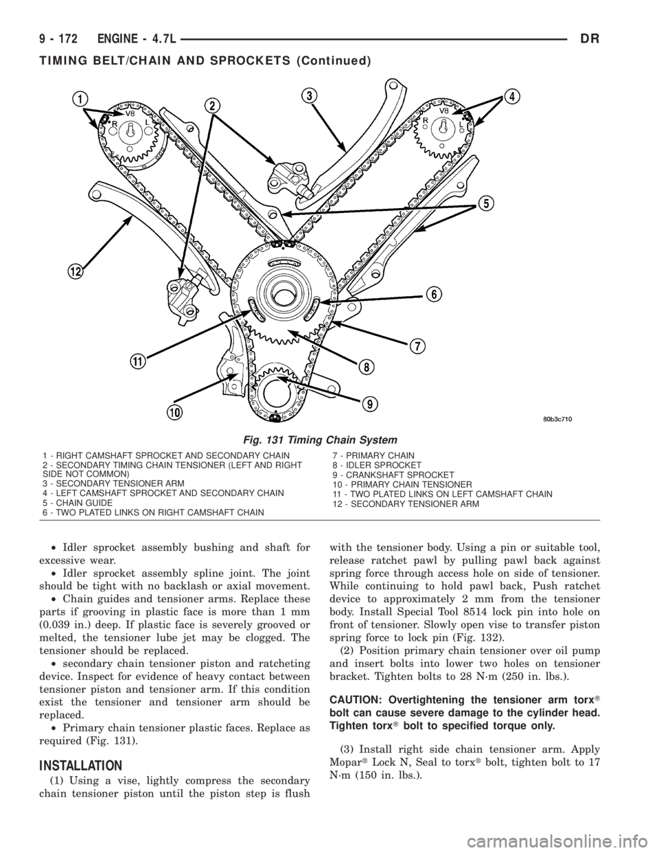
required (Fig. 131).
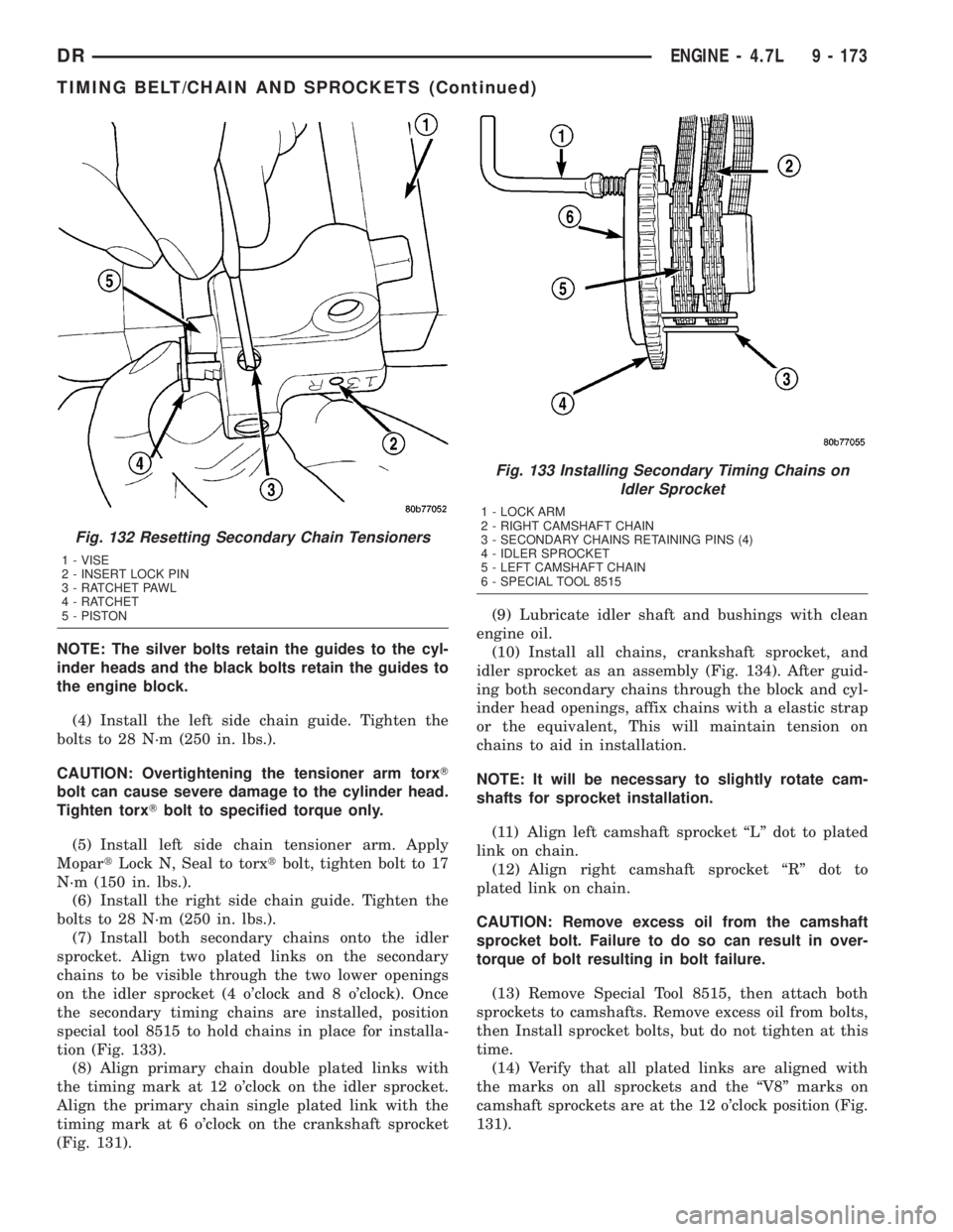
INSTALLATION
(1) Using a vise, lightly compress the secondary
chain tensioner piston until the piston step is flushwith the tensioner body. Using a pin or suitable tool,
release ratchet pawl by pulling pawl back against
spring force through access hole on side of tensioner.
While continuing to hold pawl back, Push ratchet
device to approximately 2 mm from the tensioner
body. Install Special Tool 8514 lock pin into hole on
front of tensioner. Slowly open vise to transfer piston
spring force to lock pin (Fig. 132).
(2) Position primary chain tensioner over oil pump
and insert bolts into lower two holes on tensioner
bracket. Tighten bolts to 28 N´m (250 in. lbs.).
CAUTION: Overtightening the tensioner arm torxT
bolt can cause severe damage to the cylinder head.
Tighten torxTbolt to specified torque only.
(3) Install right side chain tensioner arm. Apply
MopartLock N, Seal to torxtbolt, tighten bolt to 17
N´m (150 in. lbs.).
Fig. 131 Timing Chain System
1 - RIGHT CAMSHAFT SPROCKET AND SECONDARY CHAIN
2 - SECONDARY TIMING CHAIN TENSIONER (LEFT AND RIGHT
SIDE NOT COMMON)
3 - SECONDARY TENSIONER ARM
4 - LEFT CAMSHAFT SPROCKET AND SECONDARY CHAIN
5 - CHAIN GUIDE
6 - TWO PLATED LINKS ON RIGHT CAMSHAFT CHAIN7 - PRIMARY CHAIN
8 - IDLER SPROCKET
9 - CRANKSHAFT SPROCKET
10 - PRIMARY CHAIN TENSIONER
11 - TWO PLATED LINKS ON LEFT CAMSHAFT CHAIN
12 - SECONDARY TENSIONER ARM
9 - 172 ENGINE - 4.7LDR
TIMING BELT/CHAIN AND SPROCKETS (Continued)
Page 1422 of 2895
NOTE: The silver bolts retain the guides to the cyl-
inder heads and the black bolts retain the guides to
the engine block.
(4) Install the left side chain guide. Tighten the
bolts to 28 N´m (250 in. lbs.).
CAUTION: Overtightening the tensioner arm torxT
bolt can cause severe damage to the cylinder head.
Tighten torxTbolt to specified torque only.
(5) Install left side chain tensioner arm. Apply
MopartLock N, Seal to torxtbolt, tighten bolt to 17
N´m (150 in. lbs.).
(6) Install the right side chain guide. Tighten the
bolts to 28 N´m (250 in. lbs.).
(7) Install both secondary chains onto the idler
sprocket. Align two plated links on the secondary
chains to be visible through the two lower openings
on the idler sprocket (4 o'clock and 8 o'clock). Once
the secondary timing chains are installed, position
special tool 8515 to hold chains in place for installa-
tion (Fig. 133).
(8) Align primary chain double plated links with
the timing mark at 12 o'clock on the idler sprocket.
Align the primary chain single plated link with the
timing mark at 6 o'clock on the crankshaft sprocket
(Fig. 131).(9) Lubricate idler shaft and bushings with clean
engine oil.
(10) Install all chains, crankshaft sprocket, and
idler sprocket as an assembly (Fig. 134). After guid-
ing both secondary chains through the block and cyl-
inder head openings, affix chains with a elastic strap
or the equivalent, This will maintain tension on
chains to aid in installation.
NOTE: It will be necessary to slightly rotate cam-
shafts for sprocket installation.
(11) Align left camshaft sprocket ªLº dot to plated
link on chain.
(12) Align right camshaft sprocket ªRº dot to
plated link on chain.
CAUTION: Remove excess oil from the camshaft
sprocket bolt. Failure to do so can result in over-
torque of bolt resulting in bolt failure.
(13) Remove Special Tool 8515, then attach both
sprockets to camshafts. Remove excess oil from bolts,
then Install sprocket bolts, but do not tighten at this
time.
(14) Verify that all plated links are aligned with
the marks on all sprockets and the ªV8º marks on
camshaft sprockets are at the 12 o'clock position (Fig.
131).
Fig. 132 Resetting Secondary Chain Tensioners
1 - VISE
2 - INSERT LOCK PIN
3 - RATCHET PAWL
4 - RATCHET
5 - PISTON
Fig. 133 Installing Secondary Timing Chains on
Idler Sprocket
1 - LOCK ARM
2 - RIGHT CAMSHAFT CHAIN
3 - SECONDARY CHAINS RETAINING PINS (4)
4 - IDLER SPROCKET
5 - LEFT CAMSHAFT CHAIN
6 - SPECIAL TOOL 8515
DRENGINE - 4.7L 9 - 173
TIMING BELT/CHAIN AND SPROCKETS (Continued)
Page 1427 of 2895
ENGINE - 5.7L
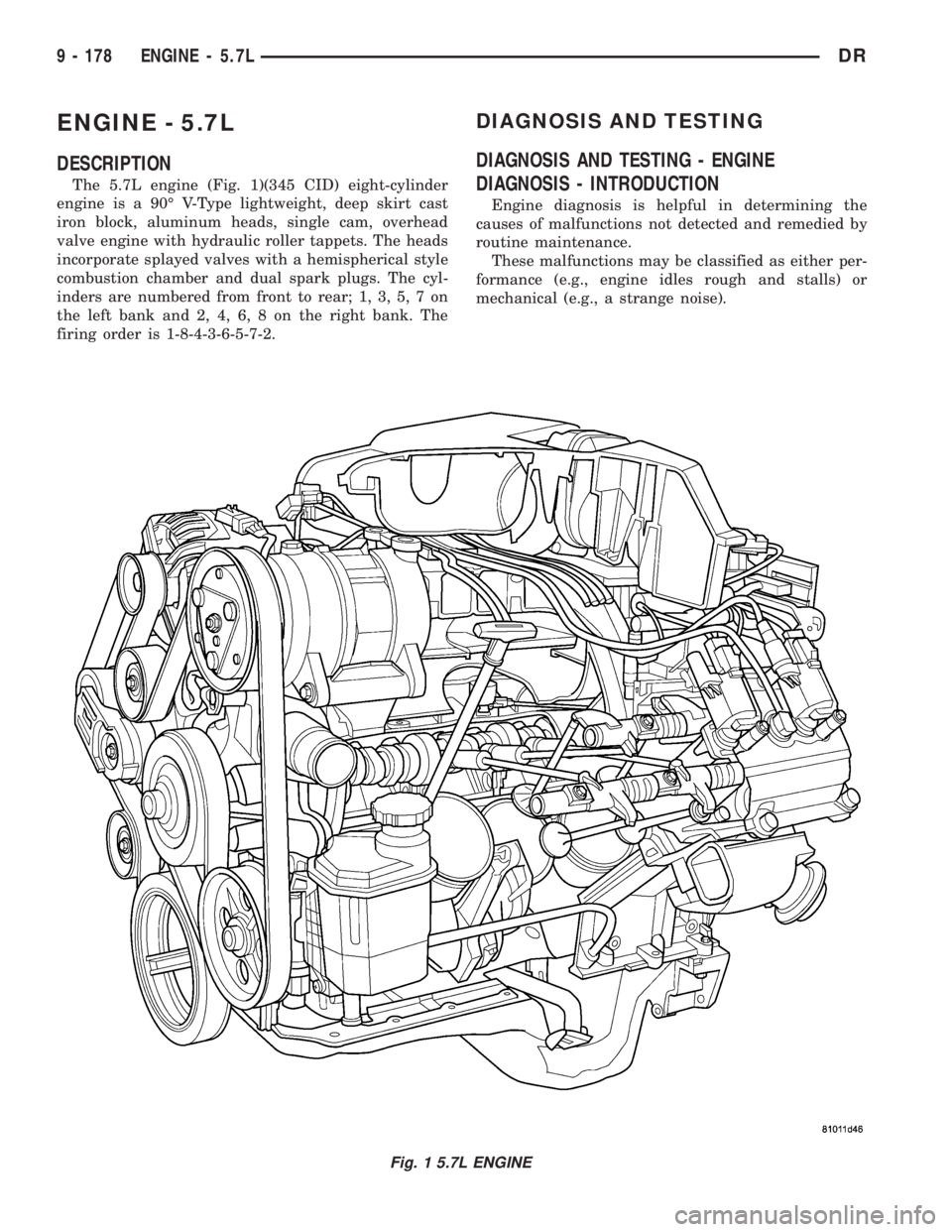
DESCRIPTION
The 5.7L engine (Fig. 1)(345 CID) eight-cylinder
engine is a 90É V-Type lightweight, deep skirt cast
iron block, aluminum heads, single cam, overhead
valve engine with hydraulic roller tappets. The heads
incorporate splayed valves with a hemispherical style
combustion chamber and dual spark plugs. The cyl-
inders are numbered from front to rear; 1, 3, 5, 7 on
the left bank and 2, 4, 6, 8 on the right bank. The
firing order is 1-8-4-3-6-5-7-2.
DIAGNOSIS AND TESTING
DIAGNOSIS AND TESTING - ENGINE
DIAGNOSIS - INTRODUCTION
Engine diagnosis is helpful in determining the
causes of malfunctions not detected and remedied by
routine maintenance.
These malfunctions may be classified as either per-
formance (e.g., engine idles rough and stalls) or
mechanical (e.g., a strange noise).
Fig. 1 5.7L ENGINE
9 - 178 ENGINE - 5.7LDR
Page 1428 of 2895
(Refer to 9 - ENGINE - DIAGNOSIS AND TEST-
ING)ÐPERFORMANCE and (Refer to 9 - ENGINE -
DIAGNOSIS AND TESTING)ÐMECHANICAL for
possible causes and corrections of malfunctions.
(Refer to 14 - FUEL SYSTEM/FUEL DELIVERY -
DIAGNOSIS AND TESTING) and (Refer to 14 -
FUEL SYSTEM/FUEL INJECTION - DIAGNOSIS
AND TESTING) for the fuel system diagnosis.
Additional tests and diagnostic procedures may be
necessary for specific engine malfunctions that can
not be isolated with the Service Diagnosis charts.
Information concerning additional tests and diagno-
sis is provided within the following diagnosis:²Cylinder Compression Pressure Test (Refer to 9 -
ENGINE - DIAGNOSIS AND TESTING).
²Cylinder Combustion Pressure Leakage Test
(Refer to 9 - ENGINE - DIAGNOSIS AND TEST-
ING).
²Engine Cylinder Head Gasket Failure Diagnosis
(Refer to 9 - ENGINE/CYLINDER HEAD - DIAGNO-
SIS AND TESTING).
²Intake Manifold Leakage Diagnosis (Refer to 9 -
ENGINE/MANIFOLDS/INTAKE MANIFOLD -
DIAGNOSIS AND TESTING).
DIAGNOSIS AND TESTING - ENGINE DIAGNOSIS - PERFORMANCE
CONDITION POSSIBLE CAUSE CORRECTION
ENGINE WILL NOT START 1. Weak battery 1. Charge or replace as necessary.
2. Corroded or loose battery
connections.2. Clean and tighten battery
connections. Apply a coat of light
mineral grease to the terminals.
3. Faulty starter. 3. (Refer to 8 - ELECTRICAL/
STARTING - DIAGNOSIS AND
TESTING).
4. Faulty coil or control unit. 4. (Refer to 8 - ELECTRICAL/
IGNITION CONTROL/IGNITION
COIL - REMOVAL).
5. Incorrect spark plug gap. 5. (Refer to 8 - ELECTRICAL/
IGNITION CONTROL/SPARK PLUG
- CLEANING).
6. Dirt or water in fuel system. 6. Clean system and replace fuel
filter.
7. Faulty fuel pump, relay or wiring. 7. Repair or replace as necessary.
ENGINE STALLS OR ROUGH IDLE 1. Idle speed set to low. 1. (Refer to 14 - FUEL SYSTEM/
FUEL INJECTION/IDLE AIR
CONTROL MOTOR - REMOVAL).
2. Idle mixture too lean or too rich. 2. Refer to Powertrain Diagnosis
Information.
3. Vacuum leak. 3. Inspect intake manifold and
vacuum hoses, repair or replace as
necessary.
4. Faulty coil. 4. (Refer to 8 - ELECTRICAL/
IGNITION CONTROL/IGNITION
COIL - REMOVAL).
5. Incorrect engine timing. 5. (Refer to 9 - ENGINE/VALVE
TIMING - STANDARD
PROCEDURE).
DRENGINE - 5.7L 9 - 179
ENGINE - 5.7L (Continued)
Page 1446 of 2895
INTAKE/EXHAUST VALVES &
SEATS
DESCRIPTION
DESCRIPTION - VALVE GUIDES
The valve guides are made of powered metal and
are pressed into the cylinder head. The guides are
not replaceable or serviceable, and valve guide ream-
ing is not recommended. If the guides are worn
beyond acceptable limits, replace the cylinder heads.
DESCRIPTION
Both the intake and exhaust valves are made of
steel. The intake valve is 50.93 mm (2.00 inches) in
diameter and the exhaust valve is 39.53 mm (1.55
inches) in diameter. All valves use three bead lock
keepers to retain the springs and promote valve rota-
tion.
STANDARD PROCEDURE - REFACING
NOTE: Valve seats that are worn or burned can be
reworked, provided that correct angle and seat
width are maintained. Otherwise the cylinder head
must be replaced.
NOTE: When refacing valves and valve seats, it is
important that the correct size valve guide pilot be
used for reseating stones. A true and complete sur-
face must be obtained.
(1) Using a suitable dial indicator measure the
center of the valve seat Total run out must not
exceed 0.051 mm (0.002 in).
(2) Apply a small amount of Prussian blue to the
valve seat, insert the valve into the cylinder head,
while applying light pressure on the valve rotate the
valve. Remove the valve and examine the valve face.
If the blue is transferred below the top edge of the
valve face, lower the valve seat using a 15 degree
stone. If the blue is transferred to the bottom edge of
the valve face, raise the valve seat using a 65 degree
stone.
(3) When the seat is properly positioned the width
of the intake seat must be 1.018 - 1.62 mm (0.0464 -
0.0637 in.) and the exhaust seat must be 1.48 - 1.92
mm (0.058 - 0.075 in.).
(4) Check the valve spring installed height after
refacing the valve and seat. The installed height for
both intake and exhaust valve springs must not
exceed 46.0 mm (1.81 in.).
VALVE FACE AND VALVE SEAT ANGLE CHART
DESCRIPTION SPECIFICATION
SEAT WIDTH
INTAKE 1.018 - 1.62 mm
(0.0464 - 0.0637 in.)
EXHAUST 1.48 - 1.92 mm
(0.058 - 0.075 in.)
FACE ANGLE
(INT. AND EXT.) 45É - 45
1¤2É
SEAT ANGLE
(INT. AND EXT.) 44
1¤2É - 45É
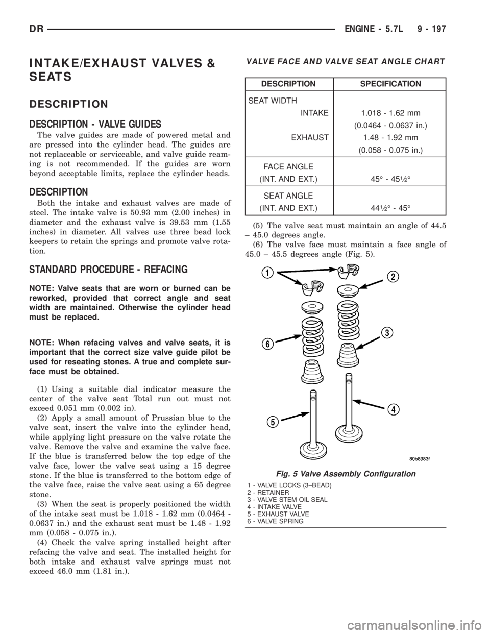
(5) The valve seat must maintain an angle of 44.5
± 45.0 degrees angle.
(6) The valve face must maintain a face angle of
45.0 ± 45.5 degrees angle (Fig. 5).
Fig. 5 Valve Assembly Configuration
1 - VALVE LOCKS (3±BEAD)
2 - RETAINER
3 - VALVE STEM OIL SEAL
4 - INTAKE VALVE
5 - EXHAUST VALVE
6 - VALVE SPRING
DRENGINE - 5.7L 9 - 197