2003 DODGE RAM light
[x] Cancel search: lightPage 1802 of 2895
INSTALLATION
WARNING: BEFORE SERVICING THE STEERING
COLUMN THE AIRBAG SYSTEM MUST BE DIS-
ARMED. REFER TO ELECTRICAL RESTRAINT SYS-
TEM FOR SERVICE PROCEDURES. FAILURE TO DO
SO MAY RESULT IN ACCIDENTAL DEPLOYMENT OF
THE AIRBAG AND POSSIBLE PERSONAL INJURY.
CAUTION: All fasteners must be torqued to specifi-
cation to ensure proper operation of the steering
column.
(1) Position the steering column on the dash panel
support and loosely install the mounting nuts.
(2) Firmly slide the steering column upward
against the studs in dash panel and hand tighten the
nuts.
(3) Install the steering shaft coupler on the steer-
ing shaft and loosely install anewbolt.
(4) Center steering column in dash opening and
tighten mounting nuts to 28 N´m (250 in. lbs.).
NOTE: Torque the upper left nut first then the lower
right nut. Then torque the lower left nut then the
upper right nut.
NOTE: A new bolt must be used for reinstallation.
(5) Tighten the coupler bolt to 57 N´m (42 ft. lbs.).
(6) Install a new brake light switch (Refer to 8 -
ELECTRICAL/LAMPS/LIGHTING - EXTERIOR/
BRAKE LAMP SWITCH - REMOVAL).(7) Install the shifter cable. (Refer to 21 - TRANS-
MISSION/TRANSAXLE/AUTOMATIC - 32RH/GEAR
SHIFT CABLE - INSTALLATION)
(8) Connect the wiring harness to the column.
(9) Install the SKIM module.
(10) Install the clockspring(Refer to 8 - ELECTRI-
CAL/RESTRAINTS/CLOCKSPRING - REMOVAL).
(11) Install the shrouds.
(12) Install the steering column opening cover
(Refer to 23 - BODY/INSTRUMENT PANEL/STEER-
ING COLUMN OPENING COVER - INSTALLA-
TION).
(13) Align the spline on the wheel hub to shaft.
(14) Then install the steering wheel and install a
newbolt. Tighten the bolt to 61 N´m (45 ft. lbs.).
(15) Install the airbag (Refer to 8 - ELECTRICAL/
RESTRAINTS/DRIVER AIRBAG - INSTALLATION).
(16) Install the two steering wheel switches.
(17) Install the tilt lever handle.
(18) Install the negative battery terminal.
(19) Test the operation of the horn, Electronic
PRNDL Indicator, lights and any other functions that
are steering column operated.IGNITION SWITCH
DESCRIPTION
The ignition switch is located on the steering col-
umn. It is used as the main on/off switching device
for most electrical components. The mechanical key
cylinder is used to engage/disengage the electrical
ignition switch.
OPERATION
Vehicles equipped with an automatic trans-
mission and a steering column mounted shifter:
an interlock device is located within the shift cable.
This interlock device is used to lock the transmission
shifter in the PARK position when the key cylinder is
in any position and the brake pedal is not depressed.
DIAGNOSIS AND TESTING - IGNITION SWITCH
TEST AND REPAIR
If the key removal effort is excessive on a vehicle
with a automatic transmission first adjust the shift
linkage, (Refer to 21 - TRANSMISSION/TRANS-
AXLE/AUTOMATIC - 46RE/GEAR SHIFT CABLE -
ADJUSTMENTS).
If the ignition switch effort is excessive remove the
ignition key cylinder from the steering column. (Refer
to 19 - STEERING/COLUMN/LOCK CYLINDER
HOUSING - REMOVAL). Check the turning effort of
the key cylinder. If the ignition key cylinder effort is
excessive replace the key cylinder.
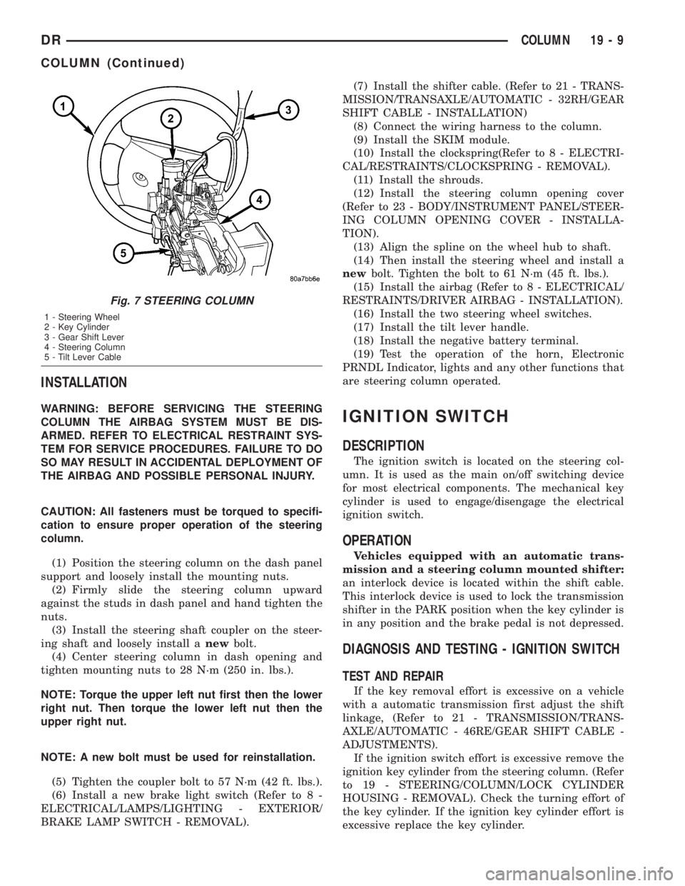
Fig. 7 STEERING COLUMN
1 - Steering Wheel
2 - Key Cylinder
3 - Gear Shift Lever
4 - Steering Column
5 - Tilt Lever Cable
DRCOLUMN 19 - 9
COLUMN (Continued)
Page 1805 of 2895
KEY CYLINDER
REMOVAL
The ignition key must be in the key cylinder for
cylinder removal.
(1) Disconnect negative cable from battery.
(2) Remove upper and lower covers (shrouds) from
steering column.
(3) Place shifter in PARK position.
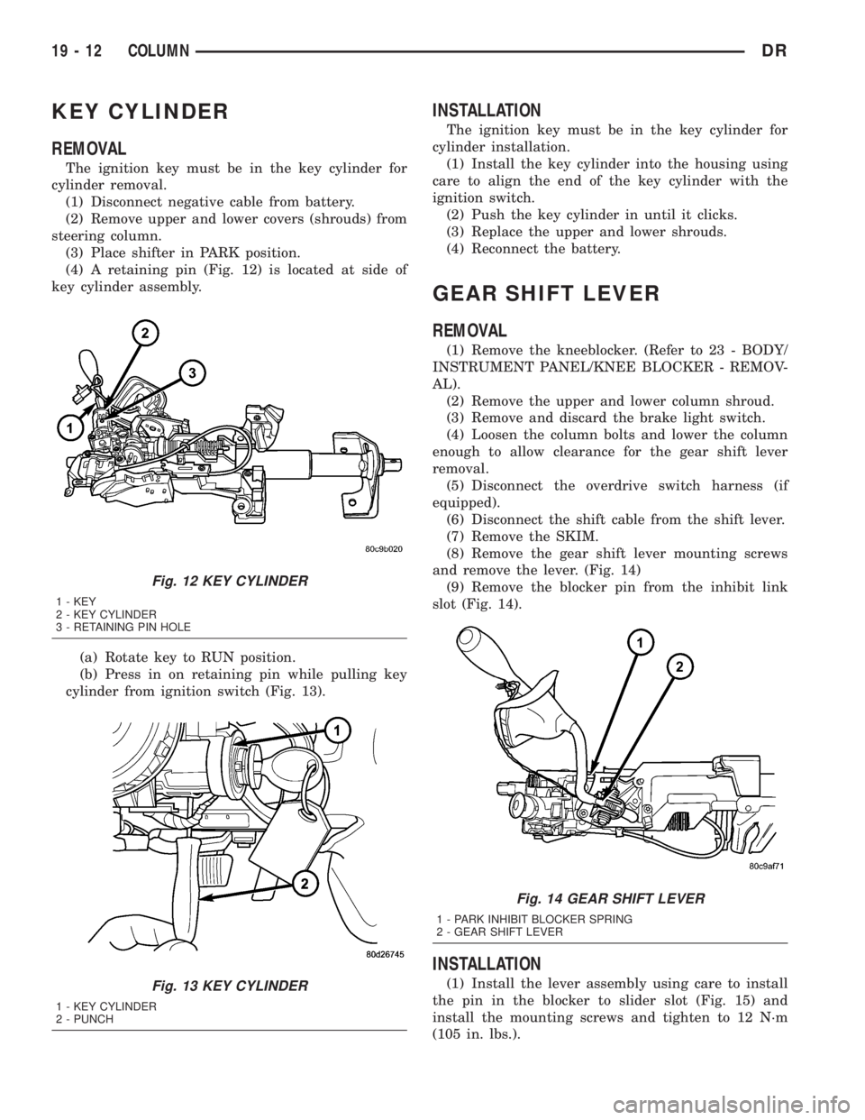
(4) A retaining pin (Fig. 12) is located at side of
key cylinder assembly.
(a) Rotate key to RUN position.
(b) Press in on retaining pin while pulling key
cylinder from ignition switch (Fig. 13).
INSTALLATION
The ignition key must be in the key cylinder for
cylinder installation.
(1) Install the key cylinder into the housing using
care to align the end of the key cylinder with the
ignition switch.
(2) Push the key cylinder in until it clicks.
(3) Replace the upper and lower shrouds.
(4) Reconnect the battery.
GEAR SHIFT LEVER
REMOVAL
(1) Remove the kneeblocker. (Refer to 23 - BODY/
INSTRUMENT PANEL/KNEE BLOCKER - REMOV-
AL).
(2) Remove the upper and lower column shroud.
(3) Remove and discard the brake light switch.
(4) Loosen the column bolts and lower the column
enough to allow clearance for the gear shift lever
removal.
(5) Disconnect the overdrive switch harness (if
equipped).
(6) Disconnect the shift cable from the shift lever.
(7) Remove the SKIM.
(8) Remove the gear shift lever mounting screws
and remove the lever. (Fig. 14)
(9) Remove the blocker pin from the inhibit link
slot (Fig. 14).
INSTALLATION
(1) Install the lever assembly using care to install
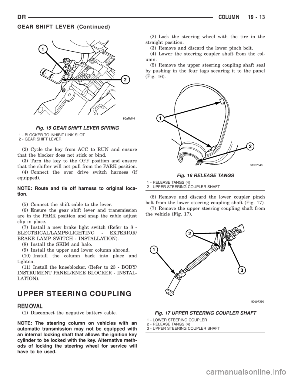
the pin in the blocker to slider slot (Fig. 15) and
install the mounting screws and tighten to 12 N´m
(105 in. lbs.).
Fig. 12 KEY CYLINDER
1 - KEY
2 - KEY CYLINDER
3 - RETAINING PIN HOLE
Fig. 13 KEY CYLINDER
1 - KEY CYLINDER
2 - PUNCH
Fig. 14 GEAR SHIFT LEVER
1 - PARK INHIBIT BLOCKER SPRING
2 - GEAR SHIFT LEVER
19 - 12 COLUMNDR
Page 1806 of 2895
(2) Cycle the key from ACC to RUN and ensure
that the blocker does not stick or bind.
(3) Turn the key to the OFF position and ensure
that the shifter will not pull from the PARK position.
(4) Connect the over drive switch harness (if
equipped).
NOTE: Route and tie off harness to original loca-
tion.
(5) Connect the shift cable to the lever.
(6) Ensure the gear shift lever and transmission
are in the PARK position and snap the cable adjust
clip in place.
(7) Install a new brake light switch (Refer to 8 -
ELECTRICAL/LAMPS/LIGHTING - EXTERIOR/
BRAKE LAMP SWITCH - INSTALLATION).
(8) Install the SKIM and halo.
(9) Install the upper and lower column shroud.
(10) Install the column back into place and
tighten.
(11) Install the kneeblocker. (Refer to 23 - BODY/
INSTRUMENT PANEL/KNEE BLOCKER - INSTAL-
LATION).
UPPER STEERING COUPLING
REMOVAL
(1) Disconnect the negative battery cable.
NOTE: The steering column on vehicles with an
automatic transmission may not be equipped with
an internal locking shaft that allows the ignition key
cylinder to be locked with the key. Alternative meth-
ods of locking the steering wheel for service will
have to be used.(2) Lock the steering wheel with the tire in the
straight position.
(3) Remove and discard the lower pinch bolt.
(4) Lower the steering coupler shaft from the col-
umn.
(5) Remove the upper steering coupling shaft seal
by pushing in the four tags securing it to the panel
(Fig. 16).
(6) Remove and discard the lower coupler pinch
bolt from the lower steering coupling shaft (Fig. 17).
(7) Remove the upper steering coupling shaft from
the vehicle (Fig. 17).
Fig. 15 GEAR SHIFT LEVER SPRING
1 - BLOCKER TO INHIBIT LINK SLOT
2 - GEAR SHIFT LEVER
Fig. 16 RELEASE TANGS
1 - RELEASE TANGS (4)
2 - UPPER STEERING COUPLER SHAFT
Fig. 17 UPPER STEERING COUPLER SHAFT
1 - LOWER STEERING COUPLER
2 - RELEASE TANGS (4)
3 - UPPER STEERING COUPLER SHAFT
DRCOLUMN 19 - 13
GEAR SHIFT LEVER (Continued)
Page 1842 of 2895
DIAGNOSIS AND TESTING
LOW LUBRICANT LEVEL
A low transmission lubricant level is generally the
result of a leak, inadequate lubricant fill or an incor-
rect lubricant level check. Leaks can occur at the
mating surfaces of the gear case, adaptor or exten-
sion housing, or from the front/rear seals. A sus-
pected leak could also be the result of an overfill
condition.
Leaks at the rear of the extension or adapter hous-
ing will be from the housing oil seals. Leaks at com-
ponent mating surfaces will probably be the result of
inadequate sealer, gaps in the sealer, incorrect bolt
tightening or use of a non-recommended sealer.
A leak at the front of the transmission will be from
either the front bearing retainer or retainer seal.
Lubricant may be seen dripping from the clutch
housing after extended operation. If the leak is
severe, it may also contaminate the clutch disc caus-
ing the disc to slip, grab and or chatter.
A correct lubricant level check can only be made
when the vehicle is level. Also allow the lubricant to
settle for a minute or so before checking. These rec-
ommendations will ensure an accurate check and
avoid an underfill or overfill condition. Always check
the lubricant level after any addition of fluid to avoid
an incorrect lubricant level condition.
HARD SHIFTING
Hard shifting is usually caused by a low lubricant
level, improper or contaminated lubricants. The con-
sequence of using non-recommended lubricants is
noise, excessive wear, internal bind and hard shift-
ing. Substantial lubricant leaks can result in gear,
shift rail, synchro, and bearing damage. If a leak
goes undetected for an extended period, the first indi-
cations of component damage are usually hard shift-
ing and noise.
Shift component damage or damaged clutch pres-
sure plate or disc are additional probable causes of
increased shift effort. Worn/damaged pressure plate
or disc can cause incorrect release. If clutch problem
is advanced, gear clash during shifts can result.
Worn or damaged synchro rings can cause gear clash
when shifting into any forward gear. In some new or
rebuilt transmissions, new synchro rings may tend to
stick slightly causing hard or noisy shifts. In most
cases this condition will decline as the rings wear-in.
TRANSMISSION NOISE
Most manual transmissions make some noise dur-
ing normal operation. Rotating gears generate a mild
whine that is audible, but generally only at extreme
speeds.Severe highly audible transmission noise is gener-
ally the initial indicator of a lubricant problem.
Insufficient, improper or contaminated lubricant will
promote rapid wear of gears, synchros, shift rails,
forks and bearings. The overheating caused by a
lubricant problem, can also lead to gear and bearing
damage.
REMOVAL
(1) Disconnect battery negative cable.
(2) Shift transmission into Neutral.
(3) Remove shift boot bezel screws and slide boot
upward on shift lever extension.
(4) Remove shift lever extension from the shift
tower and lever assembly.
(5) Raise vehicle on hoist.
(6) Remove skid plate, if equipped.
(7) Drain lubricant if transmission will be disas-
sembled for service.
(8) Mark propeller shaft/shafts and companion
flange yoke/yokes for installation reference and
remove propeller shaft/shafts.
(9) Disconnect harness from clips on transmission
housing.
(10) Remove transfer case linkage if equipped.
(11) Remove transfer case mounting nuts and
remove transfer case if equipped.
(12) Remove slave cylinder mounting nut and
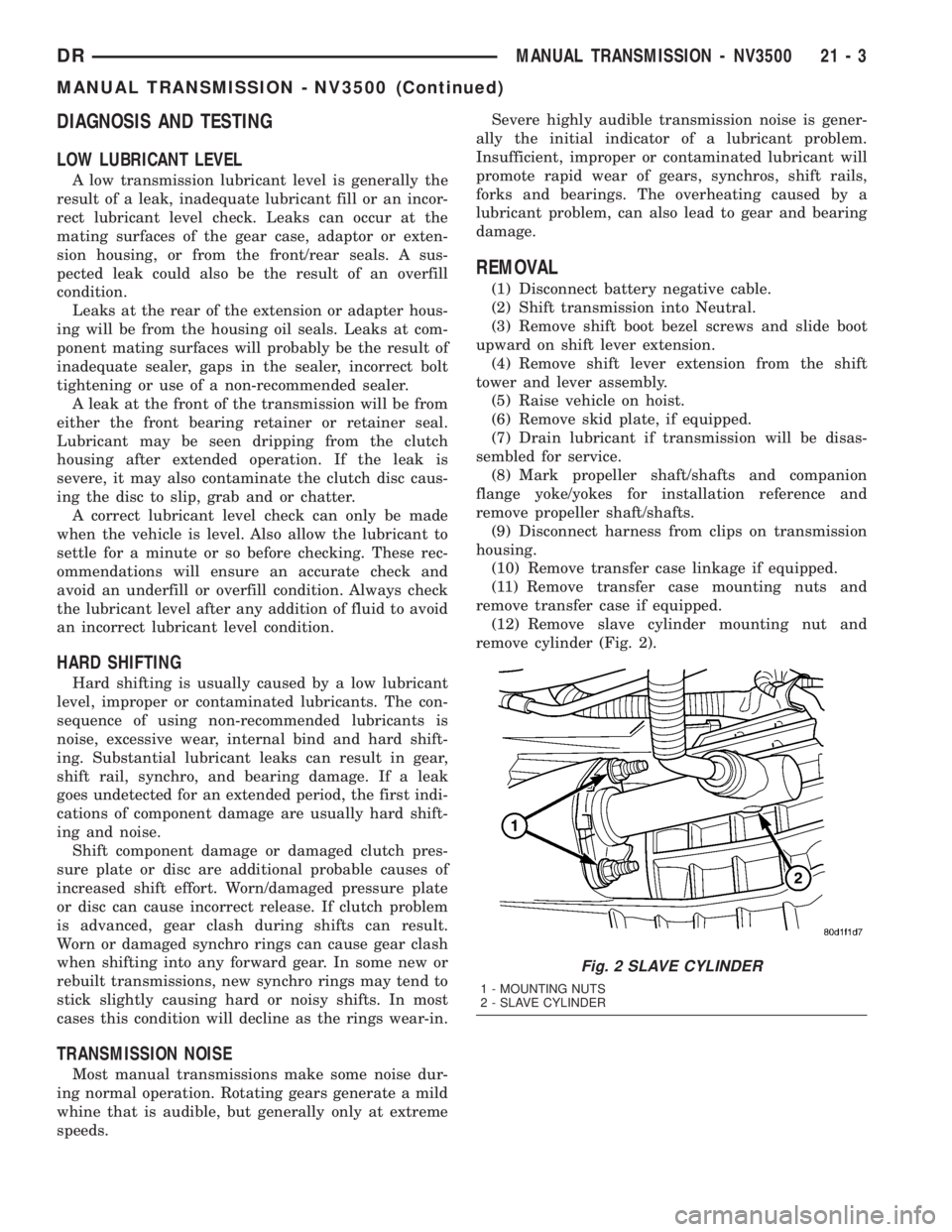
remove cylinder (Fig. 2).
Fig. 2 SLAVE CYLINDER
1 - MOUNTING NUTS
2 - SLAVE CYLINDER
DRMANUAL TRANSMISSION - NV3500 21 - 3
MANUAL TRANSMISSION - NV3500 (Continued)
Page 1843 of 2895
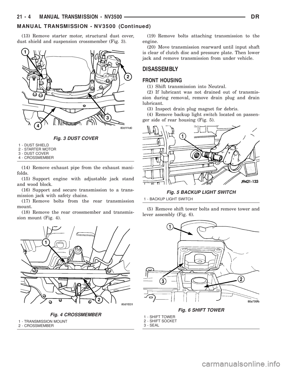
(13) Remove starter motor, structural dust cover,
dust shield and suspension crossmember (Fig. 3).
(14) Remove exhaust pipe from the exhaust mani-
folds.
(15) Support engine with adjustable jack stand
and wood block.
(16) Support and secure transmission to a trans-
mission jack with safety chains.
(17) Remove bolts from the rear transmission
mount.
(18) Remove the rear crossmember and transmis-
sion mount (Fig. 4).(19) Remove bolts attaching transmission to the
engine.
(20) Move transmission rearward until input shaft
is clear of clutch disc and pressure plate. Then lower
jack and remove transmission from under vehicle.
DISASSEMBLY
FRONT HOUSING
(1) Shift transmission into Neutral.
(2) If lubricant was not drained out of transmis-
sion during removal, remove drain plug and drain
lubricant.
(3) Inspect drain plug magnet for debris.
(4) Remove backup light switch located on passen-
ger side of rear housing (Fig. 5).
(5) Remove shift tower bolts and remove tower and
lever assembly (Fig. 6).
Fig. 3 DUST COVER
1 - DUST SHIELD
2 - STARTER MOTOR
3 - DUST COVER
4 - CROSSMEMBER
Fig. 4 CROSSMEMBER
1 - TRANSMISSION MOUNT
2 - CROSSMEMBER
Fig. 5 BACKUP LIGHT SWITCH
1 - BACKUP LIGHT SWITCH
Fig. 6 SHIFT TOWER
1 - SHIFT TOWER
2 - SHIFT SOCKET
3 - SEAL
21 - 4 MANUAL TRANSMISSION - NV3500DR
MANUAL TRANSMISSION - NV3500 (Continued)
Page 1869 of 2895
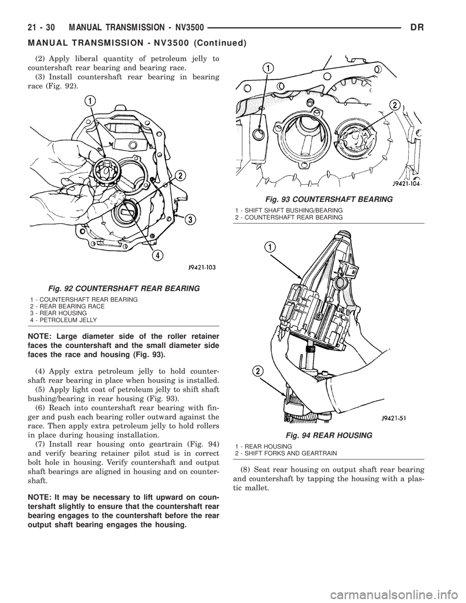
(2) Apply liberal quantity of petroleum jelly to
countershaft rear bearing and bearing race.
(3) Install countershaft rear bearing in bearing
race (Fig. 92).
NOTE: Large diameter side of the roller retainer
faces the countershaft and the small diameter side
faces the race and housing (Fig. 93).
(4) Apply extra petroleum jelly to hold counter-
shaft rear bearing in place when housing is installed.
(5) Apply light coat of petroleum jelly to shift shaft
bushing/bearing in rear housing (Fig. 93).
(6) Reach into countershaft rear bearing with fin-
ger and push each bearing roller outward against the
race. Then apply extra petroleum jelly to hold rollers
in place during housing installation.
(7) Install rear housing onto geartrain (Fig. 94)
and verify bearing retainer pilot stud is in correct
bolt hole in housing. Verify countershaft and output
shaft bearings are aligned in housing and on counter-
shaft.
NOTE: It may be necessary to lift upward on coun-
tershaft slightly to ensure that the countershaft rear
bearing engages to the countershaft before the rear
output shaft bearing engages the housing.(8) Seat rear housing on output shaft rear bearing
and countershaft by tapping the housing with a plas-
tic mallet.
Fig. 92 COUNTERSHAFT REAR BEARING
1 - COUNTERSHAFT REAR BEARING
2 - REAR BEARING RACE
3 - REAR HOUSING
4 - PETROLEUM JELLY
Fig. 93 COUNTERSHAFT BEARING
1 - SHIFT SHAFT BUSHING/BEARING
2 - COUNTERSHAFT REAR BEARING
Fig. 94 REAR HOUSING
1 - REAR HOUSING
2 - SHIFT FORKS AND GEARTRAIN
21 - 30 MANUAL TRANSMISSION - NV3500DR
MANUAL TRANSMISSION - NV3500 (Continued)
Page 1870 of 2895
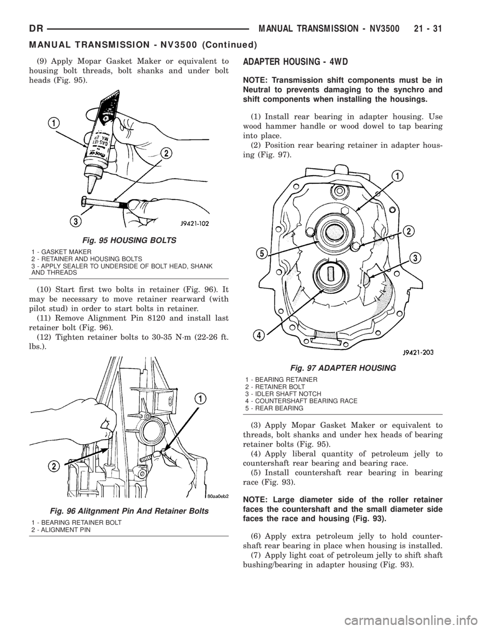
(9) Apply Mopar Gasket Maker or equivalent to
housing bolt threads, bolt shanks and under bolt
heads (Fig. 95).
(10) Start first two bolts in retainer (Fig. 96). It
may be necessary to move retainer rearward (with
pilot stud) in order to start bolts in retainer.
(11) Remove Alignment Pin 8120 and install last
retainer bolt (Fig. 96).
(12) Tighten retainer bolts to 30-35 N´m (22-26 ft.
lbs.).ADAPTER HOUSING - 4WD
NOTE: Transmission shift components must be in
Neutral to prevents damaging to the synchro and
shift components when installing the housings.
(1) Install rear bearing in adapter housing. Use
wood hammer handle or wood dowel to tap bearing
into place.
(2) Position rear bearing retainer in adapter hous-
ing (Fig. 97).
(3) Apply Mopar Gasket Maker or equivalent to
threads, bolt shanks and under hex heads of bearing
retainer bolts (Fig. 95).
(4) Apply liberal quantity of petroleum jelly to
countershaft rear bearing and bearing race.
(5) Install countershaft rear bearing in bearing
race (Fig. 93).
NOTE: Large diameter side of the roller retainer
faces the countershaft and the small diameter side
faces the race and housing (Fig. 93).
(6) Apply extra petroleum jelly to hold counter-
shaft rear bearing in place when housing is installed.
(7) Apply light coat of petroleum jelly to shift shaft
bushing/bearing in adapter housing (Fig. 93).
Fig. 95 HOUSING BOLTS
1 - GASKET MAKER
2 - RETAINER AND HOUSING BOLTS
3 - APPLY SEALER TO UNDERSIDE OF BOLT HEAD, SHANK
AND THREADS
Fig. 96 Alitgnment Pin And Retainer Bolts
1 - BEARING RETAINER BOLT
2 - ALIGNMENT PIN
Fig. 97 ADAPTER HOUSING
1 - BEARING RETAINER
2 - RETAINER BOLT
3 - IDLER SHAFT NOTCH
4 - COUNTERSHAFT BEARING RACE
5 - REAR BEARING
DRMANUAL TRANSMISSION - NV3500 21 - 31
MANUAL TRANSMISSION - NV3500 (Continued)
Page 1876 of 2895
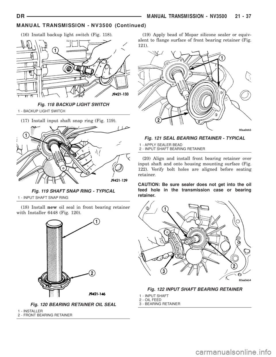
(16) Install backup light switch (Fig. 118).
(17) Install input shaft snap ring (Fig. 119).
(18) Installnewoil seal in front bearing retainer
with Installer 6448 (Fig. 120).(19) Apply bead of Mopar silicone sealer or equiv-
alent to flange surface of front bearing retainer (Fig.
121).
(20) Align and install front bearing retainer over
input shaft and onto housing mounting surface (Fig.
122). Verify bolt holes are aligned before seating
retainer.
CAUTION: Be sure sealer does not get into the oil
feed hole in the transmission case or bearing
retainer.
Fig. 118 BACKUP LIGHT SWITCH
1 - BACKUP LIGHT SWITCH
Fig. 119 SHAFT SNAP RING - TYPICAL
1 - INPUT SHAFT SNAP RING
Fig. 120 BEARING RETAINER OIL SEAL
1 - INSTALLER
2 - FRONT BEARING RETAINER
Fig. 121 SEAL BEARING RETAINER - TYPICAL
1 - APPLY SEALER BEAD
2 - INPUT SHAFT BEARING RETAINER
Fig. 122 INPUT SHAFT BEARING RETAINER
1 - INPUT SHAFT
2 - OIL FEED
3 - BEARING RETAINER
DRMANUAL TRANSMISSION - NV3500 21 - 37
MANUAL TRANSMISSION - NV3500 (Continued)