2003 DODGE RAM transmission oil
[x] Cancel search: transmission oilPage 347 of 2895

(6) Remove the power steering cooler mounting
bolts and position the power steering cooler out of
the way.
(7) Disconnect the transmission cooler lines at the
transmission. The transmission cooler will remain on
the radiator and can be removed as an assembly.
(8) Remove the lower shroud assembly and the
electronic viscous fan wiring from the upper shroud
assembly.
(9) Remove the two radiator upper mounting bolts
(Fig. 36).
(10) Lift radiator straight up and out of engine
compartment. The bottom of the radiator is equipped
with two alignment dowels that fit into holes in the
lower radiator support panel. Rubber biscuits (insu-
lators) are installed to these dowels. Take care not to
damage cooling fins or tubes on the radiator and air
conditioning condenser when removing.
CLEANING
Clean radiator fins are necessary for good heat
transfer. The radiator and oil cooler fins should be
cleaned when an accumulation of debris has
occurred. With the engine cold, apply cold water and
compressed air to the back (engine side) of the radi-
ator to flush the radiator and/or oil coolers of debris.
INSPECTION
Inspect the radiator side tanks for cracks, broken
or missing fittings also inspect the joint where the
tanks seam up to the radiator core for signs of leak-
age and/or deteriorating seals.
Inspect radiator core for corroded, bent or missing
cooling fins. Inspect the core for bent or damaged
cooling tubes.
INSTALLATION
(1) Install rubber insulators to alignment dowels
at lower part of radiator.
(2) Lower the radiator into position while guiding
the two alignment dowels into lower radiator sup-
port. Different alignment holes are provided in the
lower radiator support for each engine application.
(3) Install two upper radiator mounting bolts.
Tighten bolts to 11 N´m (95 in. lbs.) torque.
(4) Connect both radiator hoses and install hose
clamps.
(5) Connect transmission cooler lines to radiator
tank. Inspect quick connect fittings for debris and
install until an audible ªclickº is heard. Pull apart to
verify connection.
(6) Position power steering cooler on the radiator
and tighten nuts to 8.5M´N (75 in. lbs.)
(7) Attach electronic viscous fan wiring to upper
shroud ands install lower shroud.
(8) Position coolant recover tank hose, washer bot-
tle hose and the positive battery cable into the clips
located on the top of the radiator.
(9) Install air box and turbocharger inlet hose.
Tighten clamps to 4 N´M (35 in. lbs.).
(10) Position heater controls tofull heatposition.
(11) Fill cooling system with coolant (Refer to 7 -
COOLING - STANDARD PROCEDURE).
(12) Operate engine until it reaches normal tem-
perature. Check cooling system and automatic trans-
mission (if equipped) fluid levels.
RADIATOR PRESSURE CAP
DESCRIPTION
All cooling systems are equipped with a pressure
cap (Fig. 37). For 5.9L engines, the pressure cap is
located on top of the radiator outlet tank. For the
3.7L/4.7L engines, the pressure cap is located on top
of the coolant degas container. The cap releases pres-
sure at some point within a range of 97-to-124 kPa
(14-to-18 psi). The pressure relief point (in pounds) is
engraved on top of the cap
The cooling system will operate at pressures
slightly above atmospheric pressure. This results in a
higher coolant boiling point allowing increased radi-
ator cooling capacity. The cap contains a spring-
Fig. 36 Fan Shroud MountingÐ5.9L Diesel Engine
1 - RADIATOR SUPPORT
2 - UPPER FAN SHROUD
3 - BOLTS (2)
4 - LOWER FAN SHROUD
5 - RADIATOR
7 - 60 ENGINEDR
RADIATOR - 5.9L DIESEL (Continued)
Page 359 of 2895
TRANSMISSION
TABLE OF CONTENTS
page page
TRANS COOLER
DESCRIPTION
DESCRIPTION........................72
DESCRIPTION........................72
OPERATION...........................72
REMOVAL.............................72
DISASSEMBLY - 5.9L ONLY...............73
ASSEMBLY - 5.9L ONLY..................73
INSTALLATION.........................73TRANS COOLER - 5.9L DIESEL
DESCRIPTION.........................73
OPERATION...........................74
REMOVAL
REMOVALÐAIR TO OIL COOLER.........74
REMOVALÐWATER TO OIL COOLER......74
INSTALLATION
INSTALLATIONÐAIR TO OIL COOLER.....75
INSTALLATION.......................75
TRANS COOLER
DESCRIPTION
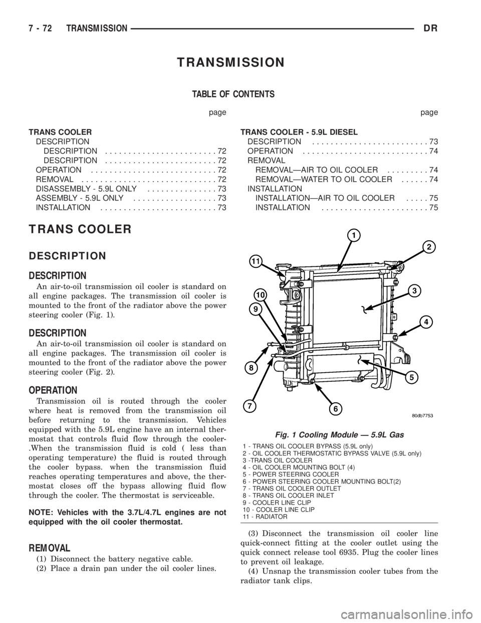
DESCRIPTION
An air-to-oil transmission oil cooler is standard on
all engine packages. The transmission oil cooler is
mounted to the front of the radiator above the power
steering cooler (Fig. 1).
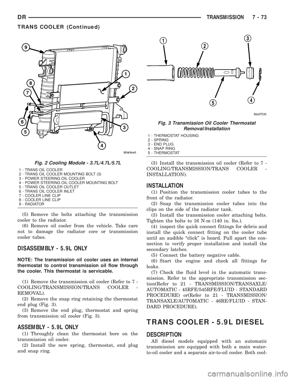
DESCRIPTION
An air-to-oil transmission oil cooler is standard on
all engine packages. The transmission oil cooler is
mounted to the front of the radiator above the power
steering cooler (Fig. 2).
OPERATION
Transmission oil is routed through the cooler
where heat is removed from the transmission oil
before returning to the transmission. Vehicles
equipped with the 5.9L engine have an internal ther-
mostat that controls fluid flow through the cooler-
.When the transmission fluid is cold ( less than
operating temperature) the fluid is routed through
the cooler bypass. when the transmission fluid
reaches operating temperatures and above, the ther-
mostat closes off the bypass allowing fluid flow
through the cooler. The thermostat is serviceable.
NOTE: Vehicles with the 3.7L/4.7L engines are not
equipped with the oil cooler thermostat.
REMOVAL
(1) Disconnect the battery negative cable.
(2) Place a drain pan under the oil cooler lines.(3) Disconnect the transmission oil cooler line
quick-connect fitting at the cooler outlet using the
quick connect release tool 6935. Plug the cooler lines
to prevent oil leakage.
(4) Unsnap the transmission cooler tubes from the
radiator tank clips.
Fig. 1 Cooling Module Ð 5.9L Gas
1 - TRANS OIL COOLER BYPASS (5.9L only)
2 - OIL COOLER THERMOSTATIC BYPASS VALVE (5.9L only)
3 -TRANS OIL COOLER
4 - OIL COOLER MOUNTING BOLT (4)
5 - POWER STEERING COOLER
6 - POWER STEERING COOLER MOUNTING BOLT(2)
7 - TRANS OIL COOLER OUTLET
8 - TRANS OIL COOLER INLET
9 - COOLER LINE CLIP
10 - COOLER LINE CLIP
11 - RADIATOR
7 - 72 TRANSMISSIONDR
Page 360 of 2895
(5) Remove the bolts attaching the transmission
cooler to the radiator.
(6) Remove oil cooler from the vehicle. Take care
not to damage the radiator core or transmission
cooler tubes.
DISASSEMBLY - 5.9L ONLY
NOTE: The transmission oil cooler uses an internal
thermostat to control transmission oil flow through
the cooler. This thermostat is servicable.
(1) Remove the transmission oil cooler (Refer to 7 -
COOLING/TRANSMISSION/TRANS COOLER -
REMOVAL).
(2) Remove the snap ring retaining the thermostat
end plug (Fig. 3).
(3) Remove the end plug, thermostat and spring
from transmission oil cooler (Fig. 3).
ASSEMBLY - 5.9L ONLY
(1) Throughly clean the thermostat bore on the
transmission oil cooler.
(2) Install the new spring, thermostat, end plug
and snap ring.(3) Install the transmission oil cooler (Refer to 7 -
COOLING/TRANSMISSION/TRANS COOLER -
INSTALLATION).
INSTALLATION
(1) Position the transmission cooler tubes to the
front of the radiator.
(2) Snap the transmission cooler tubes into the
clips on the side of the radiator tank.
(3) Install the transmission cooler attaching bolts.
Tighten the bolts to 16 N´m (140 in. lbs.).
(4) inspect the quick connect fittings for debris and
install the quick connect fitting on the cooler tube
until an audible ªclickº is heard. Pull apart the con-
nection to verify proper installation and install the
secondary latches.
(5) Connect the battery negative cable.
(6) Start the engine and check all fittings for
leaks.
(7) Check the fluid level in the automatic trans-
mission. Refer to the appropriate transmission sec-
tion(Refer to 21 - TRANSMISSION/TRANSAXLE/
AUTOMATIC - 45RFE/545RFE/FLUID - STANDARD
PROCEDURE) or(Refer to 21 - TRANSMISSION/
TRANSAXLE/AUTOMATIC - 46RE/FLUID - STAN-
DARD PROCEDURE).
TRANS COOLER - 5.9L DIESEL
DESCRIPTION
All diesel models equipped with an automatic
transmission are equipped with both a main water-
to-oil cooler and a separate air-to-oil cooler. Both cool-
Fig. 2 Cooling Module - 3.7L/4.7L/5.7L
1 - TRANS OIL COOLER
2 - TRANS OIL COOLER MOUNTING BOLT (3)
3 - POWER STEERING OIL COOLER
4 - POWER STEERING OIL COOLER MOUNTING BOLT
5 - TRANS OIL COOLER OUTLET
6 - TRANS OIL COOLER INLET
7 - COOLER LINE CLIP
8 - COOLER LINE CLIP
9 - RADIATOR
Fig. 3 Transmission Oil Cooler Thermostat
Removal/Installation
1 - THERMOSTAT HOUSING
2 - SPRING
3 - END PLUG
4 - SNAP RING
5 - THERMOSTAT
DRTRANSMISSION 7 - 73
TRANS COOLER (Continued)
Page 361 of 2895
ers are supplied as standard equipment on diesel
engine powered models when equipped with an auto-
matic transmission.
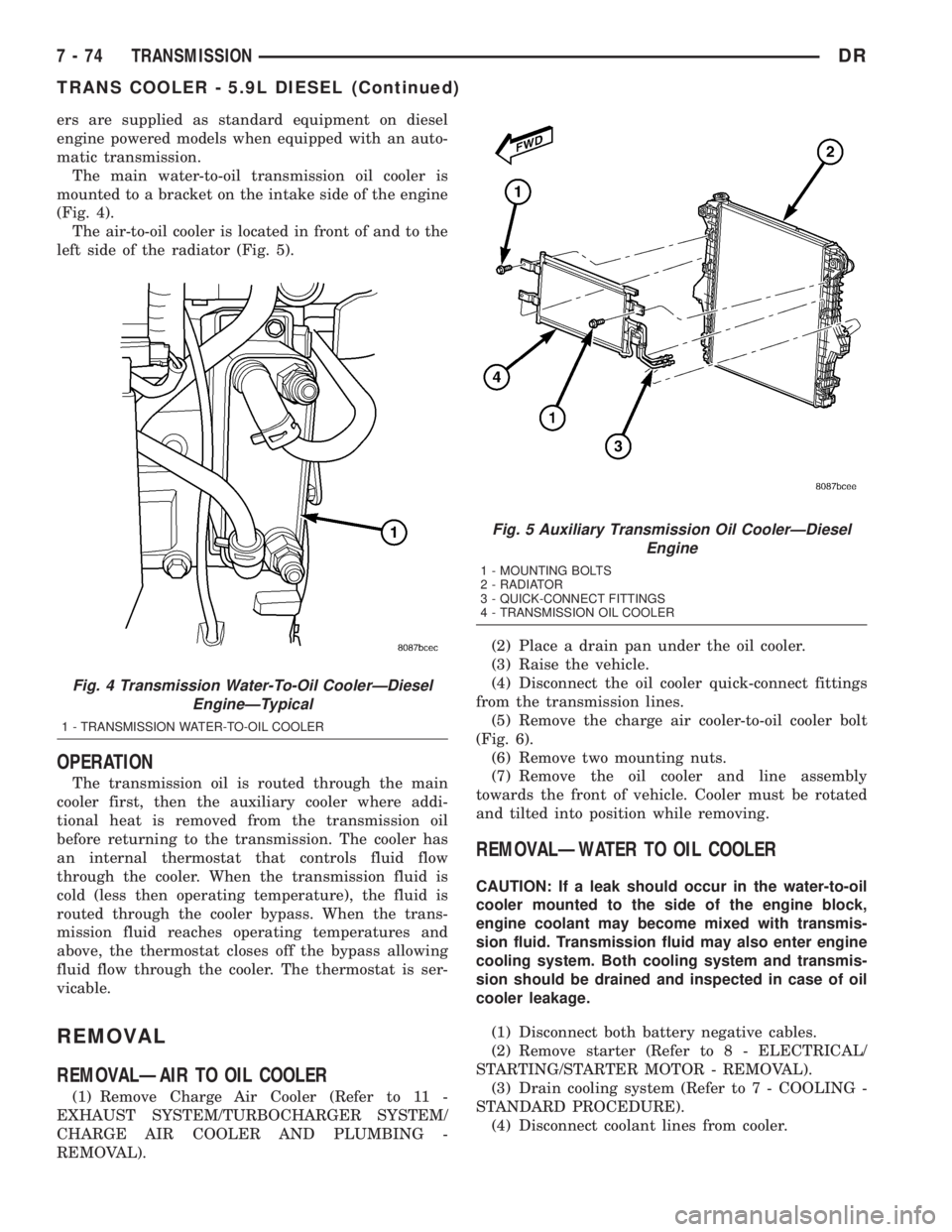
The main water-to-oil transmission oil cooler is
mounted to a bracket on the intake side of the engine
(Fig. 4).
The air-to-oil cooler is located in front of and to the
left side of the radiator (Fig. 5).
OPERATION
The transmission oil is routed through the main
cooler first, then the auxiliary cooler where addi-
tional heat is removed from the transmission oil
before returning to the transmission. The cooler has
an internal thermostat that controls fluid flow
through the cooler. When the transmission fluid is
cold (less then operating temperature), the fluid is
routed through the cooler bypass. When the trans-
mission fluid reaches operating temperatures and
above, the thermostat closes off the bypass allowing
fluid flow through the cooler. The thermostat is ser-
vicable.
REMOVAL
REMOVALÐAIR TO OIL COOLER
(1) Remove Charge Air Cooler (Refer to 11 -
EXHAUST SYSTEM/TURBOCHARGER SYSTEM/
CHARGE AIR COOLER AND PLUMBING -
REMOVAL).(2) Place a drain pan under the oil cooler.
(3) Raise the vehicle.
(4) Disconnect the oil cooler quick-connect fittings
from the transmission lines.
(5) Remove the charge air cooler-to-oil cooler bolt
(Fig. 6).
(6) Remove two mounting nuts.
(7) Remove the oil cooler and line assembly
towards the front of vehicle. Cooler must be rotated
and tilted into position while removing.
REMOVALÐWATER TO OIL COOLER
CAUTION: If a leak should occur in the water-to-oil
cooler mounted to the side of the engine block,
engine coolant may become mixed with transmis-
sion fluid. Transmission fluid may also enter engine
cooling system. Both cooling system and transmis-
sion should be drained and inspected in case of oil
cooler leakage.
(1) Disconnect both battery negative cables.
(2) Remove starter (Refer to 8 - ELECTRICAL/
STARTING/STARTER MOTOR - REMOVAL).
(3) Drain cooling system (Refer to 7 - COOLING -
STANDARD PROCEDURE).
(4) Disconnect coolant lines from cooler.
Fig. 4 Transmission Water-To-Oil CoolerÐDiesel
EngineÐTypical
1 - TRANSMISSION WATER-TO-OIL COOLER
Fig. 5 Auxiliary Transmission Oil CoolerÐDiesel
Engine
1 - MOUNTING BOLTS
2 - RADIATOR
3 - QUICK-CONNECT FITTINGS
4 - TRANSMISSION OIL COOLER
7 - 74 TRANSMISSIONDR
TRANS COOLER - 5.9L DIESEL (Continued)
Page 362 of 2895
(5) Disconnect transmission oil lines from cooler.
Plug cooler lines to prevent oil leakage.
(6) Remove cooler bracket to transmission bolt.
(7) Remove two cooler bracket to cooler bolts.
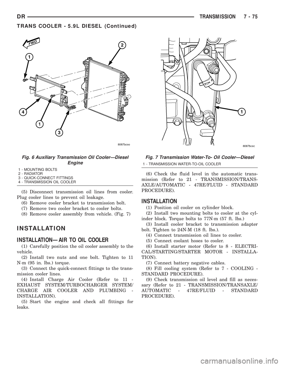
(8) Remove cooler assembly from vehicle. (Fig. 7)
INSTALLATION
INSTALLATIONÐAIR TO OIL COOLER
(1) Carefully position the oil cooler assembly to the
vehicle.
(2) Install two nuts and one bolt. Tighten to 11
N´m (95 in. lbs.) torque.
(3) Connect the quick-connect fittings to the trans-
mission cooler lines.
(4) Install Charge Air Cooler (Refer to 11 -
EXHAUST SYSTEM/TURBOCHARGER SYSTEM/
CHARGE AIR COOLER AND PLUMBING -
INSTALLATION).
(5) Start the engine and check all fittings for
leaks.(6) Check the fluid level in the automatic trans-
mission (Refer to 21 - TRANSMISSION/TRANS-
AXLE/AUTOMATIC - 47RE/FLUID - STANDARD
PROCEDURE).
INSTALLATION
(1) Position oil cooler on cylinder block.
(2) Install two mounting bolts to cooler at the cyl-
inder block. Torque bolts to 77N´m (57 ft. lbs.)
(3) Install cooler bracket to transmission adapter
bolt. Tighten to 24N´M (18 ft. lbs.).
(4) Connect transmission oil lines to cooler.
(5) Connect coolant hoses to cooler.
(6) Install starter motor (Refer to 8 - ELECTRI-
CAL/STARTING/STARTER MOTOR - INSTALLA-
TION).
(7) Connect battery negative cables.
(8) Fill cooling system (Refer to 7 - COOLING -
STANDARD PROCEDURE).
(9) Check transmission oil level and fill as neces-
sary (Refer to 21 - TRANSMISSION/TRANSAXLE/
AUTOMATIC - 47RE/FLUID - STANDARD
PROCEDURE).
Fig. 6 Auxiliary Transmission Oil CoolerÐDiesel
Engine
1 - MOUNTING BOLTS
2 - RADIATOR
3 - QUICK-CONNECT FITTINGS
4 - TRANSMISSION OIL COOLER
Fig. 7 Transmission Water-To- Oil CoolerÐDiesel
1 - TRANSMISSION WATER-TO-OIL COOLER
DRTRANSMISSION 7 - 75
TRANS COOLER - 5.9L DIESEL (Continued)
Page 392 of 2895

OPERATION
OPERATION - PCM
The PCM operates the fuel system. The PCM is a
pre-programmed, triple microprocessor digital com-
puter. It regulates ignition timing, air-fuel ratio,
emission control devices, charging system, certain
transmission features, speed control, air conditioning
compressor clutch engagement and idle speed. The
PCM can adapt its programming to meet changing
operating conditions.
The PCM receives input signals from various
switches and sensors. Based on these inputs, the
PCM regulates various engine and vehicle operations
through different system components. These compo-
nents are referred to as Powertrain Control Module
(PCM) Outputs. The sensors and switches that pro-
vide inputs to the PCM are considered Powertrain
Control Module (PCM) Inputs.
The PCM adjusts ignition timing based upon
inputs it receives from sensors that react to: engine
rpm, manifold absolute pressure, engine coolant tem-
perature, throttle position, transmission gear selec-
tion (automatic transmission), vehicle speed, power
steering pump pressure, and the brake switch.
The PCM adjusts idle speed based on inputs it
receives from sensors that react to: throttle position,
vehicle speed, transmission gear selection, engine
coolant temperature and from inputs it receives from
the air conditioning clutch switch and brake switch.
Based on inputs that it receives, the PCM adjusts
ignition coil dwell. The PCM also adjusts the gener-
ator charge rate through control of the generator
field and provides speed control operation.
NOTE: PCM Inputs:
²ABS module (if equipped)
²A/C request (if equipped with factory A/C)
²A/C select (if equipped with factory A/C)
²A/C pressure transducer
²Auto shutdown (ASD) sense
²Battery temperature sensor
²Battery voltage
²Brake switch
²J1850 bus (+) circuits
²J1850 bus (-) circuits
²Camshaft position sensor signal
²Crankshaft position sensor
²Data link connection for DRB scan tool
²EATX module (if equipped)
²Engine coolant temperature sensor
²Fuel level (through J1850 circuitry)
²Generator (battery voltage) output
²Ignition circuit sense (ignition switch in on/off/
crank/run position)²Intake manifold air temperature sensor
²Knock sensors (2 on 3.7L engine)
²Leak detection pump (switch) sense (if equipped)
²Manifold absolute pressure (MAP) sensor
²Oil pressure
²Oxygen sensors
²Park/neutral switch (auto. trans. only)
²Power ground
²Power steering pressure switch (if equipped)
²Sensor return
²Signal ground
²Speed control multiplexed single wire input
²Throttle position sensor
²Transfer case switch (4WD range position)
²Vehicle speed signal
NOTE: PCM Outputs:
²A/C clutch relay
²Auto shutdown (ASD) relay
²J1850 bus (+/-) circuits for: speedometer, voltme-
ter, fuel gauge, oil pressure gauge/lamp, engine temp.
gauge and speed control warn. lamp
²Data link connection for DRB scan tool
²EGR valve control solenoid (if equipped)
²EVAP canister purge solenoid
²Five volt sensor supply (primary)
²Five volt sensor supply (secondary)
²Fuel injectors
²Fuel pump relay
²Generator field driver (-)
²Generator field driver (+)
²Idle air control (IAC) motor
²Ignition coil(s)
²Leak detection pump (if equipped)
²Malfunction indicator lamp (Check engine lamp).
Driven through J1850 circuits.
²Oxygen sensor heater relays
²Oxygen sensors (pulse width modulated)
²Radiator cooling fan relay (pulse width modu-
lated)
²Speed control vacuum solenoid
²Speed control vent solenoid
²Tachometer (if equipped). Driven through J1850
circuits.
²Transmission convertor clutch circuit. Driven
through J1850 circuits.
OPERATION - 5 VOLT SUPPLIES
Primary 5±volt supply:
²supplies the required 5 volt power source to the
Crankshaft Position (CKP) sensor.
²supplies the required 5 volt power source to the
Camshaft Position (CMP) sensor.
²supplies a reference voltage for the Manifold
Absolute Pressure (MAP) sensor.
DRELECTRONIC CONTROL MODULES 8E - 11
POWERTRAIN CONTROL MODULE (Continued)
Page 402 of 2895
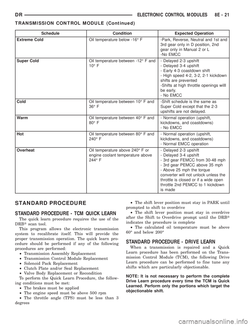
Schedule Condition Expected Operation
Extreme ColdOil temperature below -16É F -Park, Reverse, Neutral and 1st and
3rd gear only in D position, 2nd
gear only in Manual 2 or L
-No EMCC
Super ColdOil temperature between -12É F and
10É F- Delayed 2-3 upshift
- Delayed 3-4 upshift
- Early 4-3 coastdown shift
- High speed 4-2, 3-2, 2-1 kickdown
shifts are prevented
-Shifts at high throttle openings willl
be early.
- No EMCC
ColdOil temperature between 10É F and
36É F-Shift schedule is the same as
Super Cold except that the 2-3
upshifts are not delayed.
WarmOil temperature between 40É F and
80É F- Normal operation (upshift,
kickdowns, and coastdowns)
- No EMCC
HotOil temperature between 80É F and
240É F- Normal operation (upshift,
kickdowns, and coastdowns)
- Normal EMCC operation
OverheatOil temperature above 240É F or
engine coolant temperature above
244É F- Delayed 2-3 upshift
- Delayed 3-4 upshift
- 3rd gear FEMCC from 30-48 mph
- 3rd gear PEMCC above 35 mph
- Above 25 mph the torque
converter will not unlock unless the
throttle is closed or if a wide open
throttle 2nd PEMCC to 1 kickdown
is made
STANDARD PROCEDURE
STANDARD PROCEDURE - TCM QUICK LEARN
The quick learn procedure requires the use of the
DRBtscan tool.
This program allows the electronic transmission
system to recalibrate itself. This will provide the
proper transmission operation. The quick learn pro-
cedure should be performed if any of the following
procedures are performed:
²Transmission Assembly Replacement
²Transmission Control Module Replacement
²Solenoid Pack Replacement
²Clutch Plate and/or Seal Replacement
²Valve Body Replacement or Recondition
To perform the Quick Learn Procedure, the follow-
ing conditions must be met:
²The brakes must be applied
²The engine speed must be above 500 rpm
²The throttle angle (TPS) must be less than 3
degrees²The shift lever position must stay in PARK until
prompted to shift to overdrive
²The shift lever position must stay in overdrive
after the Shift to Overdrive prompt until the DRBt
indicates the procedure is complete
²The calculated oil temperature must be above
60É and below 200É
STANDARD PROCEDURE - DRIVE LEARN
When a transmission is repaired and a Quick
Learn procedure has been performed on the Trans-
mission Control Module (TCM), the following Drive
Learn procedure can be performed to fine tune any
shifts which are particularly objectionable.
NOTE: It is not necessary to perform the complete
Drive Learn procedure every time the TCM is Quick
Learned. Perform only the portions which target the
objectionable shift.
DRELECTRONIC CONTROL MODULES 8E - 21
TRANSMISSION CONTROL MODULE (Continued)
Page 403 of 2895
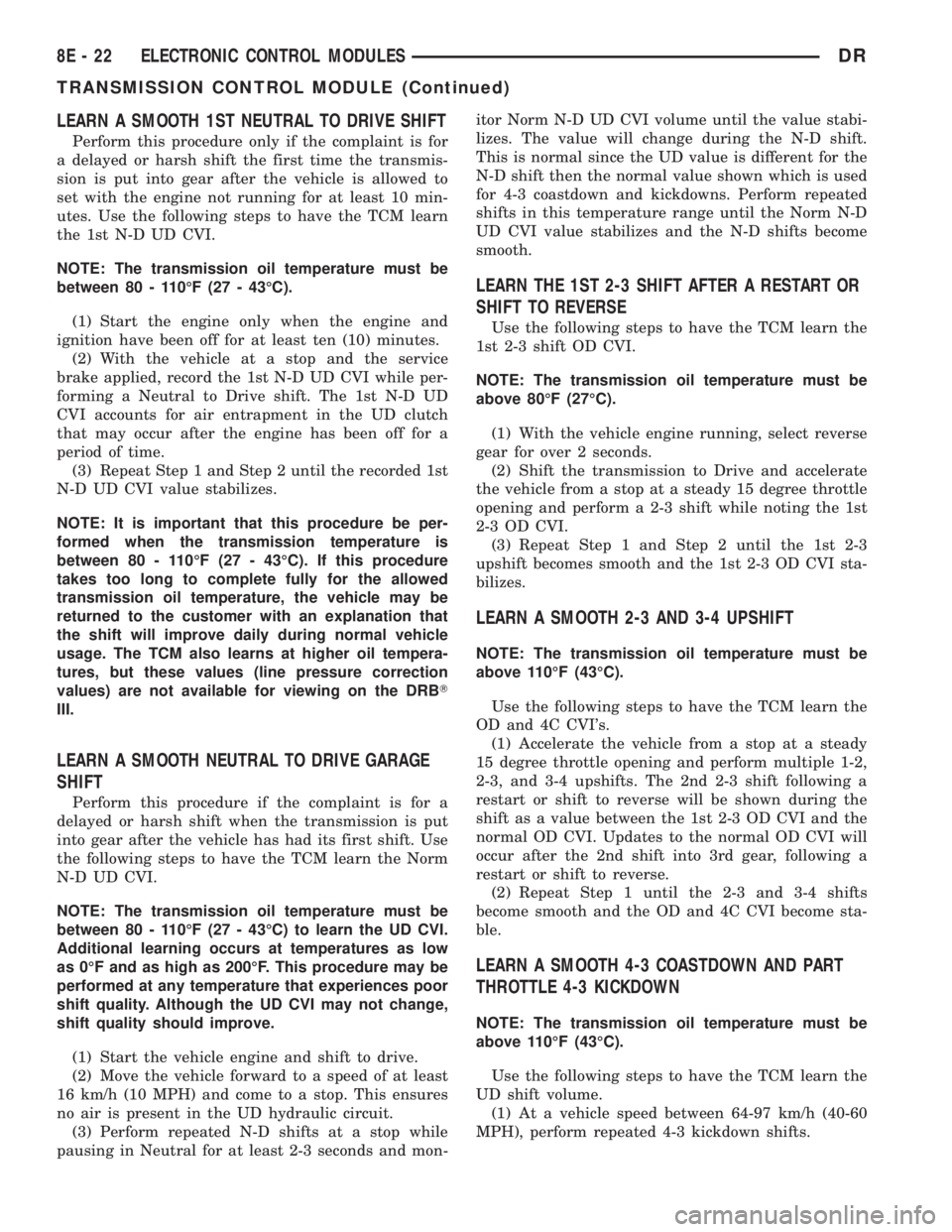
LEARN A SMOOTH 1ST NEUTRAL TO DRIVE SHIFT
Perform this procedure only if the complaint is for
a delayed or harsh shift the first time the transmis-
sion is put into gear after the vehicle is allowed to
set with the engine not running for at least 10 min-
utes. Use the following steps to have the TCM learn
the 1st N-D UD CVI.
NOTE: The transmission oil temperature must be
between 80 - 110ÉF (27 - 43ÉC).
(1) Start the engine only when the engine and
ignition have been off for at least ten (10) minutes.
(2) With the vehicle at a stop and the service
brake applied, record the 1st N-D UD CVI while per-
forming a Neutral to Drive shift. The 1st N-D UD
CVI accounts for air entrapment in the UD clutch
that may occur after the engine has been off for a
period of time.
(3) Repeat Step 1 and Step 2 until the recorded 1st
N-D UD CVI value stabilizes.
NOTE: It is important that this procedure be per-
formed when the transmission temperature is
between 80 - 110ÉF (27 - 43ÉC). If this procedure
takes too long to complete fully for the allowed
transmission oil temperature, the vehicle may be
returned to the customer with an explanation that
the shift will improve daily during normal vehicle
usage. The TCM also learns at higher oil tempera-
tures, but these values (line pressure correction
values) are not available for viewing on the DRBT
III.
LEARN A SMOOTH NEUTRAL TO DRIVE GARAGE
SHIFT
Perform this procedure if the complaint is for a
delayed or harsh shift when the transmission is put
into gear after the vehicle has had its first shift. Use
the following steps to have the TCM learn the Norm
N-D UD CVI.
NOTE: The transmission oil temperature must be
between 80 - 110ÉF (27 - 43ÉC) to learn the UD CVI.
Additional learning occurs at temperatures as low
as 0ÉF and as high as 200ÉF. This procedure may be
performed at any temperature that experiences poor
shift quality. Although the UD CVI may not change,
shift quality should improve.
(1) Start the vehicle engine and shift to drive.
(2) Move the vehicle forward to a speed of at least
16 km/h (10 MPH) and come to a stop. This ensures
no air is present in the UD hydraulic circuit.
(3) Perform repeated N-D shifts at a stop while
pausing in Neutral for at least 2-3 seconds and mon-itor Norm N-D UD CVI volume until the value stabi-
lizes. The value will change during the N-D shift.
This is normal since the UD value is different for the
N-D shift then the normal value shown which is used
for 4-3 coastdown and kickdowns. Perform repeated
shifts in this temperature range until the Norm N-D
UD CVI value stabilizes and the N-D shifts become
smooth.
LEARN THE 1ST 2-3 SHIFT AFTER A RESTART OR
SHIFT TO REVERSE
Use the following steps to have the TCM learn the
1st 2-3 shift OD CVI.
NOTE: The transmission oil temperature must be
above 80ÉF (27ÉC).
(1) With the vehicle engine running, select reverse
gear for over 2 seconds.
(2) Shift the transmission to Drive and accelerate
the vehicle from a stop at a steady 15 degree throttle
opening and perform a 2-3 shift while noting the 1st
2-3 OD CVI.
(3) Repeat Step 1 and Step 2 until the 1st 2-3
upshift becomes smooth and the 1st 2-3 OD CVI sta-
bilizes.
LEARN A SMOOTH 2-3 AND 3-4 UPSHIFT
NOTE: The transmission oil temperature must be
above 110ÉF (43ÉC).
Use the following steps to have the TCM learn the
OD and 4C CVI's.
(1) Accelerate the vehicle from a stop at a steady
15 degree throttle opening and perform multiple 1-2,
2-3, and 3-4 upshifts. The 2nd 2-3 shift following a
restart or shift to reverse will be shown during the
shift as a value between the 1st 2-3 OD CVI and the
normal OD CVI. Updates to the normal OD CVI will
occur after the 2nd shift into 3rd gear, following a
restart or shift to reverse.
(2) Repeat Step 1 until the 2-3 and 3-4 shifts
become smooth and the OD and 4C CVI become sta-
ble.
LEARN A SMOOTH 4-3 COASTDOWN AND PART
THROTTLE 4-3 KICKDOWN
NOTE: The transmission oil temperature must be
above 110ÉF (43ÉC).
Use the following steps to have the TCM learn the
UD shift volume.
(1) At a vehicle speed between 64-97 km/h (40-60
MPH), perform repeated 4-3 kickdown shifts.
8E - 22 ELECTRONIC CONTROL MODULESDR
TRANSMISSION CONTROL MODULE (Continued)