2003 DODGE RAM transmission oil
[x] Cancel search: transmission oilPage 480 of 2895

The PCM adjusts ignition timing based on inputs it
receives from:
²The engine coolant temperature sensor
²The crankshaft position sensor (engine speed)
²The camshaft position sensor (crankshaft posi-
tion)
²The manifold absolute pressure (MAP) sensor
²The throttle position sensor
²Transmission gear selection
REMOVAL
3.7L V-6
An individual ignition coil is used for each spark
plug (Fig. 30). The coil fits into machined holes in the
cylinder head. A mounting stud/nut secures each coil
to the top of the intake manifold (Fig. 31). The bot-
tom of the coil is equipped with a rubber boot to seal
the spark plug to the coil. Inside each rubber boot is
a spring. The spring is used for a mechanical contact
between the coil and the top of the spark plug. These
rubber boots and springs are a permanent part of the
coil and are not serviced separately. An o-ring (Fig.
30) is used to seal the coil at the opening into the cyl-
inder head.
(1) Depending on which coil is being removed, the
throttle body air intake tube or intake box may need
to be removed to gain access to coil.
(2) Disconnect electrical connector from coil by
pushing downward on release lock on top of connec-
tor and pull connector from coil.
(3) Clean area at base of coil with compressed air
before removal.
(4) Remove coil mounting nut from mounting stud
(Fig. 31).
(5) Carefully pull up coil from cylinder head open-
ing with a slight twisting action.
(6) Remove coil from vehicle.
4.7L V-8
An individual ignition coil is used for each spark
plug (Fig. 30). The coil fits into machined holes in the
cylinder head. A mounting stud/nut secures each coil
to the top of the intake manifold (Fig. 32). The bot-
tom of the coil is equipped with a rubber boot to seal
the spark plug to the coil. Inside each rubber boot is
a spring. The spring is used for a mechanical contact
between the coil and the top of the spark plug. These
rubber boots and springs are a permanent part of the
coil and are not serviced separately. An o-ring (Fig.
30) is used to seal the coil at the opening into the cyl-
inder head.
(1) Depending on which coil is being removed, the
throttle body air intake tube or intake box may need
to be removed to gain access to coil.(2) Disconnect electrical connector (Fig. 32) from
coil by pushing downward on release lock on top of
connector and pull connector from coil.
(3) Clean area at base of coil with compressed air
before removal.
(4) Remove coil mounting nut from mounting stud
(Fig. 32).
(5) Carefully pull up coil from cylinder head open-
ing with a slight twisting action.
(6) Remove coil from vehicle.
5.7L V-8
Before removing or disconnecting any spark plug
cables, note their original position. Remove cables
one-at-a-time. To prevent ignition crossfire, spark
plug cablesMUSTbe placed in cable tray (routing
loom) into their original position.
An individual ignition coil (Fig. 33) is used at each
cylinder. The coil mounts to the top of the valve cover
with 2 bolts (Fig. 34). The bottom of the coil is
equipped with a rubber boot to seal the spark plug to
the coil. Inside each rubber boot is a spring. The
spring is used for a mechanical contact between the
coil and the top of the spark plug.
(1) Depending on which coil is being removed, the
throttle body air intake tube or intake box may need
to be removed to gain access to coil.
(2) Unlock electrical connector (Fig. 34) by moving
slide lock first. Press on release lock (Fig. 34) while
pulling electrical connector from coil.
(3) Disconnect secondary high-voltage cable from
coil with a twisting action.
(4) Clean area at base of coil with compressed air
before removal.
(5) Remove 2 mounting bolts (note that mounting
bolts are retained to coil).
(6) Carefully pull up coil from cylinder head open-
ing with a slight twisting action.
(7) Remove coil from vehicle.
(8) Before installing spark plug cables to either the
spark plugs or coils, or before installing a coil to a
spark plug, apply dielectric grease to inside of boots.
5.9L V-8
The coil is not oil filled. The coil windings are
embedded in an epoxy compound. This provides heat
and vibration resistance that allows the coil to be
mounted on the engine. If the coil is replaced, it must
be replaced with the same type.
5.9L V-8 LDC-Gas Engines: The coil is mounted to
a bracket that is bolted to the front of the right
engine cylinder head (Fig. 35). This bracket is
mounted on top of the automatic belt tensioner
bracket using common bolts.
DRIGNITION CONTROL 8I - 23
IGNITION COIL (Continued)
Page 498 of 2895

the vehicle speed remains greater than about twenty-
four kilometers-per-hour (fifteen miles-per-hour).
²Vacuum Fluorescent Display Synchroniza-
tion- The EMIC transmits electronic panel lamp
dimming level messages which allows all other elec-
tronic modules on the PCI data bus with Vacuum
Fluorescent Display (VFD) units to coordinate their
illumination intensity with that of the EMIC VFD
units.
²Vehicle Theft Security System- The EMIC
monitors inputs from the door cylinder lock switch-
(es), the door ajar switches, the ignition switch, and
the Remote Keyless Entry (RKE) receiver module,
then provides electronic horn and lighting request
messages to the Front Control Module (FCM) located
on the Integrated Power Module (IPM) for the appro-
priate VTSS alarm output features.
²Wiper/Washer System Control- The EMIC
provides electronic wiper and/or washer request mes-
sages to the Front Control Module (FCM) located on
the Integrated Power Module (IPM) for the appropri-
ate wiper and washer system features. (Refer to 8 -
ELECTRICAL/WIPERS/WASHERS - DESCRIP-
TION).
The EMIC houses six analog gauges and has pro-
visions for up to twenty-three indicators (Fig. 3) or
(Fig. 4). The EMIC includes the following analog
gauges:
²Coolant Temperature Gauge
²Fuel Gauge
²Oil Pressure Gauge
²Speedometer
²Tachometer
²Voltage Gauge
Some of the EMIC indicators are automatically
configured when the EMIC is connected to the vehi-
cle electrical system for compatibility with certain
optional equipment or equipment required for regula-
tory purposes in certain markets. While each EMIC
may have provisions for indicators to support every
available option, the configurable indicators will not
be functional in a vehicle that does not have the
equipment that an indicator supports. The EMIC
includes provisions for the following indicators (Fig.
3) or (Fig. 4):
²Airbag Indicator (with Airbag System only)
²Antilock Brake System (ABS) Indicator
(with ABS or Rear Wheel Anti-Lock [RWAL]
brakes only)
²Brake Indicator
²Cargo Lamp Indicator
²Check Gauges Indicator
²Cruise Indicator (with Speed Control only)
²Door Ajar Indicator
²Electronic Throttle Control (ETC) Indicator
(with 5.7L Gasoline Engine only)²Gear Selector Indicator (with Automatic
Transmission only)
²High Beam Indicator
²Lamp Out Indicator
²Low Fuel Indicator
²Malfunction Indicator Lamp (MIL)
²Overdrive-Off Indicator (with Automatic
Transmission only)
²Seatbelt Indicator
²Security Indicator (with Sentry Key Immo-
bilizer & Vehicle Theft Security Systems only)
²Service Four-Wheel Drive Indicator (with
Four-Wheel Drive only)
²Transmission Overtemp Indicator (with
Automatic Transmission only)
²Turn Signal (Right and Left) Indicators
²Upshift Indicator (with Manual Transmis-
sion only)
²Washer Fluid Indicator
²Wait-To-Start Indicator (with Diesel Engine
only)
²Water-In-Fuel Indicator (with Diesel Engine
only)
Each indicator in the EMIC, except those located
within one of the VFD units, is illuminated by a ded-
icated LED that is soldered onto the EMIC electronic
circuit board. The LED units are not available for
service replacement and, if damaged or faulty, the
entire EMIC must be replaced. Cluster illumination
is accomplished by dimmable incandescent back
lighting, which illuminates the gauges for visibility
when the exterior lighting is turned on. Each of the
incandescent bulbs is secured by an integral bulb
holder to the electronic circuit board from the back of
the cluster housing.
Hard wired circuitry connects the EMIC to the
electrical system of the vehicle. These hard wired cir-
cuits are integral to several wire harnesses, which
are routed throughout the vehicle and retained by
many different methods. These circuits may be con-
nected to each other, to the vehicle electrical system
and to the EMIC through the use of a combination of
soldered splices, splice block connectors, and many
different types of wire harness terminal connectors
and insulators. Refer to the appropriate wiring infor-
mation. The wiring information includes wiring dia-
grams, proper wire and connector repair procedures,
further details on wire harness routing and reten-
tion, as well as pin-out and location views for the
various wire harness connectors, splices and grounds.
The EMIC modules for this model are serviced only
as complete units. The EMIC module cannot be
adjusted or repaired. If a gauge, an LED indicator, a
VFD unit, the electronic circuit board, the circuit
board hardware, the cluster overlay, or the EMIC
housing are damaged or faulty, the entire EMIC mod-
DRINSTRUMENT CLUSTER 8J - 5
INSTRUMENT CLUSTER (Continued)
Page 499 of 2895

ule must be replaced. The cluster lens, hood and
mask unit and the individual incandescent lamp
bulbs with holders are available for individual ser-
vice replacement.
OPERATION
The ElectroMechanical Instrument Cluster (EMIC)
in this model also includes the hardware and soft-
ware necessary to serve as the electronic body control
module and is sometimes referred to as the Cab
Compartment Node or CCN. The following informa-
tion deals primarily with the instrument cluster
functions of this unit. Additional details of the elec-
tronic body control functions of this unit may be
found within the service information for the system
or component that the EMIC controls. For example:
Additional details of the audible warning functions of
the EMIC are found within the Chime/Buzzer service
information.The EMIC is designed to allow the vehicle operator
to monitor the conditions of many of the vehicle com-
ponents and operating systems. The gauges and indi-
cators in the EMIC provide valuable information
about the various standard and optional powertrains,
fuel and emissions systems, cooling systems, lighting
systems, safety systems and many other convenience
items. The EMIC is installed in the instrument panel
so that all of these monitors can be easily viewed by
the vehicle operator when driving, while still allow-
ing relative ease of access for service. The micropro-
cessor-based EMIC hardware and software uses
various inputs to control the gauges and indicators
visible on the face of the cluster. Some of these
inputs are hard wired, but most are in the form of
electronic messages that are transmitted by other
electronic modules over the Programmable Communi-
cations Interface (PCI) data bus network. (Refer to 8
- ELECTRICAL/ELECTRONIC CONTROL MOD-
ULES/COMMUNICATION - OPERATION).
Fig. 3 Gauges & Indicators - Gasoline Engine
1 - MALFUNCTION INDICATOR LAMP 13 - ELECTRONIC THROTTLE CONTROL (ETC) INDICATOR
2 - VOLTAGE GAUGE 14 - ENGINE TEMPERATURE GAUGE
3 - LEFT TURN INDICATOR 15 - SECURITY INDICATOR
4 - TACHOMETER 16 - GEAR SELECTOR INDICATOR DISPLAY (INCLUDES
CRUISE & UPSHIFT INDICATORS)
5 - AIRBAG INDICATOR 17 - CHECK GAUGES INDICATOR
6 - HIGH BEAM INDICATOR 18 - BRAKE INDICATOR
7 - SEATBELT INDICATOR 19 - ABS INDICATOR
8 - SPEEDOMETER 20 - ODOMETER/TRIP ODOMETER DISPLAY (INCLUDES
ENGINE HOURS, WASHER FLUID, LAMP OUTAGE,
OVERDRIVE-OFF & SERVICE 4x4 INDICATORS)
9 - RIGHT TURN INDICATOR 21 - ODOMETER/TRIP ODOMETER SWITCH BUTTON
10 - OIL PRESSURE GAUGE 22 - FUEL GAUGE
11 - CARGO LAMP INDICATOR 23 - LOW FUEL INDICATOR
12 - DOOR AJAR INDICATOR 24 - TRANSMISSION OVERTEMP INDICATOR
8J - 6 INSTRUMENT CLUSTERDR
INSTRUMENT CLUSTER (Continued)
Page 500 of 2895
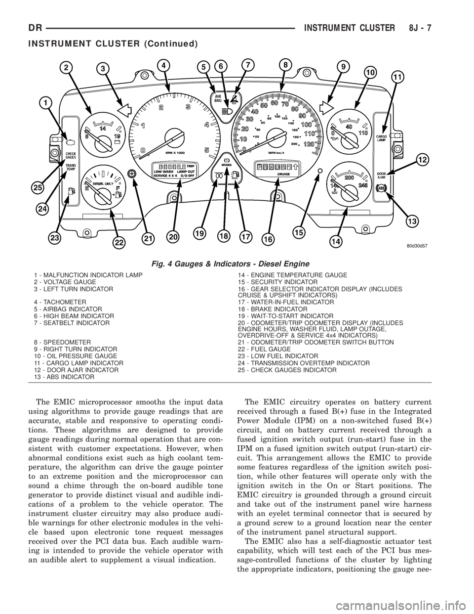
The EMIC microprocessor smooths the input data
using algorithms to provide gauge readings that are
accurate, stable and responsive to operating condi-
tions. These algorithms are designed to provide
gauge readings during normal operation that are con-
sistent with customer expectations. However, when
abnormal conditions exist such as high coolant tem-
perature, the algorithm can drive the gauge pointer
to an extreme position and the microprocessor can
sound a chime through the on-board audible tone
generator to provide distinct visual and audible indi-
cations of a problem to the vehicle operator. The
instrument cluster circuitry may also produce audi-
ble warnings for other electronic modules in the vehi-
cle based upon electronic tone request messages
received over the PCI data bus. Each audible warn-
ing is intended to provide the vehicle operator with
an audible alert to supplement a visual indication.The EMIC circuitry operates on battery current
received through a fused B(+) fuse in the Integrated
Power Module (IPM) on a non-switched fused B(+)
circuit, and on battery current received through a
fused ignition switch output (run-start) fuse in the
IPM on a fused ignition switch output (run-start) cir-
cuit. This arrangement allows the EMIC to provide
some features regardless of the ignition switch posi-
tion, while other features will operate only with the
ignition switch in the On or Start positions. The
EMIC circuitry is grounded through a ground circuit
and take out of the instrument panel wire harness
with an eyelet terminal connector that is secured by
a ground screw to a ground location near the center
of the instrument panel structural support.
The EMIC also has a self-diagnostic actuator test
capability, which will test each of the PCI bus mes-
sage-controlled functions of the cluster by lighting
the appropriate indicators, positioning the gauge nee-
Fig. 4 Gauges & Indicators - Diesel Engine
1 - MALFUNCTION INDICATOR LAMP 14 - ENGINE TEMPERATURE GAUGE
2 - VOLTAGE GAUGE 15 - SECURITY INDICATOR
3 - LEFT TURN INDICATOR 16 - GEAR SELECTOR INDICATOR DISPLAY (INCLUDES
CRUISE & UPSHIFT INDICATORS)
4 - TACHOMETER 17 - WATER-IN-FUEL INDICATOR
5 - AIRBAG INDICATOR 18 - BRAKE INDICATOR
6 - HIGH BEAM INDICATOR 19 - WAIT-TO-START INDICATOR
7 - SEATBELT INDICATOR 20 - ODOMETER/TRIP ODOMETER DISPLAY (INCLUDES
ENGINE HOURS, WASHER FLUID, LAMP OUTAGE,
OVERDRIVE-OFF & SERVICE 4x4 INDICATORS)
8 - SPEEDOMETER 21 - ODOMETER/TRIP ODOMETER SWITCH BUTTON
9 - RIGHT TURN INDICATOR 22 - FUEL GAUGE
10 - OIL PRESSURE GAUGE 23 - LOW FUEL INDICATOR
11 - CARGO LAMP INDICATOR 24 - TRANSMISSION OVERTEMP INDICATOR
12 - DOOR AJAR INDICATOR 25 - CHECK GAUGES INDICATOR
13 - ABS INDICATOR
DRINSTRUMENT CLUSTER 8J - 7
INSTRUMENT CLUSTER (Continued)
Page 501 of 2895

dles at several predetermined calibration points
across the gauge faces, and illuminating all segments
of the odometer/trip odometer and gear selector indi-
cator Vacuum-Fluorescent Display (VFD) units.
(Refer to 8 - ELECTRICAL/INSTRUMENT CLUS-
TER - DIAGNOSIS AND TESTING). See the owner's
manual in the vehicle glove box for more information
on the features, use and operation of the EMIC.
GAUGES
All gauges receive battery current through the
EMIC circuitry only when the ignition switch is in
the On or Start positions. With the ignition switch in
the Off position battery current is not supplied to
any gauges, and the EMIC circuitry is programmed
to move all of the gauge needles back to the low end
of their respective scales. Therefore, the gauges do
not accurately indicate any vehicle condition unless
the ignition switch is in the On or Start positions.
All of the EMIC gauges are air core magnetic
units. Two fixed electromagnetic coils are located
within each gauge. These coils are wrapped at right
angles to each other around a movable permanent
magnet. The movable magnet is suspended within
the coils on one end of a pivot shaft, while the gauge
needle is attached to the other end of the shaft. One
of the coils has a fixed current flowing through it to
maintain a constant magnetic field strength. Current
flow through the second coil changes, which causes
changes in its magnetic field strength. The current
flowing through the second coil is changed by the
EMIC circuitry in response to messages received over
the PCI data bus. The gauge needle moves as the
movable permanent magnet aligns itself to the
changing magnetic fields created around it by the
electromagnets.
The gauges are diagnosed using the EMIC self-di-
agnostic actuator test. (Refer to 8 - ELECTRICAL/
INSTRUMENT CLUSTER - DIAGNOSIS AND
TESTING). Proper testing of the PCI data bus and
the electronic data bus message inputs to the EMIC
that control each gauge require the use of a DRBIIIt
scan tool. Refer to the appropriate diagnostic infor-
mation. Specific operation details for each gauge may
be found elsewhere in this service information.
VACUUM-FLUORESCENT DISPLAYS
The Vacuum-Fluorescent Display (VFD) units are
soldered to the EMIC electronic circuit board. With
the ignition switch in the Off or Accessory positions,
the odometer display is activated when the driver
door is opened (Rental Car mode) and is deactivated
when the driver door is closed. Otherwise, both dis-
play units are active when the ignition switch is in
the On or Start positions, and inactive when the igni-
tion switch is in the Off or Accessory positions.The illumination intensity of the VFD units is con-
trolled by the EMIC circuitry based upon an input
from the headlamp switch and a dimming level input
received from the headlamp dimmer switch. The
EMIC synchronizes the illumination intensity of
other VFD units with that of the units in the EMIC
by sending electronic dimming level messages to
other electronic modules in the vehicle over the PCI
data bus.
The EMIC VFD units have several display capabil-
ities including odometer, trip odometer, engine hours,
gear selector indication (PRNDL) for models with an
automatic transmission, several warning or reminder
indications, and various diagnostic information when
certain fault conditions exist. An odometer/trip odom-
eter switch on the EMIC circuit board is used to con-
trol some of the display modes. This switch is
actuated manually by depressing the odometer/trip
odometer switch button that extends through the
lower edge of the cluster lens, just left of the tachom-
eter. Actuating this switch momentarily with the
ignition switch in the On position will toggle the
VFD between the odometer and trip odometer modes.
Depressing the switch button for about two seconds
while the VFD is in the trip odometer mode will
reset the trip odometer value to zero. While in the
odometer mode with the ignition switch in the On
position and the engine not running, depressing this
switch for about six seconds will display the engine
hours information. Holding this switch depressed
while turning the ignition switch from the Off posi-
tion to the On position will initiate the EMIC self-di-
agnostic actuator test. Refer to the appropriate
diagnostic information for additional details on this
VFD function. The EMIC microprocessor remembers
which display mode is active when the ignition
switch is turned to the Off position, and returns the
VFD display to that mode when the ignition switch is
turned On again.
The VFD units are diagnosed using the EMIC self-
diagnostic actuator test. (Refer to 8 - ELECTRICAL/
INSTRUMENT CLUSTER - DIAGNOSIS AND
TESTING). Proper testing of the PCI data bus and
the electronic data bus message inputs to the EMIC
that control some of the VFD functions requires the
use of a DRBIIItscan tool. Refer to the appropriate
diagnostic information. Specific operation details for
the odometer, the trip odometer, the gear selector
indicator and the various warning and reminder indi-
cator functions of the VFD may be found elsewhere
in this service information.
INDICATORS
Indicators are located in various positions within
the EMIC and are all connected to the EMIC elec-
tronic circuit board. The cargo lamp indicator, door
8J - 8 INSTRUMENT CLUSTERDR
INSTRUMENT CLUSTER (Continued)
Page 526 of 2895

ECM indicating the engine oil pressure is below
about 41 kPa (6 psi), the gauge needle is moved to
the graduation at the far left end of the gauge scale,
the check gauges indicator is illuminated, and a sin-
gle chime tone is generated. The gauge needle
remains at the left end of the gauge scale and the
check gauges indicator remains illuminated until the
cluster receives a message from the PCM or ECM
indicating that the engine oil pressure is above about
41 kPa (6 psi), or until the ignition switch is turned
to the Off position, whichever occurs first. The clus-
ter will only turn the check gauges indicator on in
response to an engine oil pressure low message if the
engine speed message is greater than zero.
²Communication Error- If the cluster fails to
receive an engine oil pressure message, it will hold
the gauge needle at the last indication about five sec-
onds or until the ignition switch is turned to the Off
position, whichever occurs first. After five seconds,
the cluster will move the gauge needle to the left end
of the gauge scale.
²Actuator Test- Each time the cluster is put
through the actuator test, the oil pressure gauge nee-
dle will be swept to several calibration points on the
gauge scale in a prescribed sequence in order to con-
firm the functionality of the gauge and the cluster
control circuitry.
On vehicles with a gasoline engine, the PCM con-
tinually monitors the engine oil pressure sensor to
determine the engine oil pressure. On vehicles with a
diesel engine, the ECM continually monitors the
engine oil pressure sensor to determine the engine oil
pressure. The PCM or ECM then sends the proper
engine oil pressure messages to the instrument clus-
ter. For further diagnosis of the oil pressure gauge or
the instrument cluster circuitry that controls the
gauge, (Refer to 8 - ELECTRICAL/INSTRUMENT
CLUSTER - DIAGNOSIS AND TESTING). If the
instrument cluster turns on the check gauges indica-
tor due to a low oil pressure gauge reading, it may
indicate that the engine or the engine oiling system
requires service. For proper diagnosis of the engine
oil pressure sensor, the PCM, the ECM, the PCI data
bus, or the electronic message inputs to the instru-
ment cluster that control the oil pressure gauge, a
DRBIIItscan tool is required. Refer to the appropri-
ate diagnostic information.
OVERDRIVE OFF INDICATOR
DESCRIPTION
An overdrive off indicator is standard equipment
on all instrument clusters. However, on vehicles not
equipped with the optional overdrive automatic
transmission, this indicator is electronically disabled.The overdrive off indicator consists of the words ªO/D
OFFº, which appear in the lower portion of the odom-
eter/trip odometer indicator Vacuum Fluorescent Dis-
play (VFD) unit. The VFD is soldered onto the
cluster electronic circuit board and is visible through
a window with a smoked clear lens located on the
lower edge of the tachometer gauge dial face of the
cluster overlay. The dark lens over the VFD prevents
the indicator from being clearly visible when it is not
illuminated. The words ªO/D OFFº appear in an
amber color and at the same lighting level as the
odometer/trip odometer information when they are
illuminated by the instrument cluster electronic cir-
cuit board. The overdrive off indicator is serviced as
a unit with the VFD in the instrument cluster.
OPERATION
The overdrive off indicator gives an indication to
the vehicle operator when the Off position of the
overdrive off switch has been selected, disabling the
electronically controlled overdrive feature of the auto-
matic transmission. This indicator is controlled by
the instrument cluster circuit board based upon clus-
ter programming and electronic messages received by
the cluster from the Powertrain Control Module
(PCM) over the Programmable Communications
Interface (PCI) data bus. The overdrive off indicator
is completely controlled by the instrument cluster
logic circuit, and that logic will only allow this indi-
cator to operate when the instrument cluster receives
a battery current input on the fused ignition switch
output (run-start) circuit. Therefore, the indicator
will always be off when the ignition switch is in any
position except On or Start. The indicator only illu-
minates when it is switched to ground by the instru-
ment cluster circuitry. The instrument cluster will
turn on the overdrive off indicator for the following
reasons:
²Overdrive Off Lamp-On Message- Each time
the cluster receives an overdrive off lamp-on message
from the PCM indicating that the Off position of the
overdrive off switch has been selected, the overdrive
off indicator will be illuminated. The indicator
remains illuminated until the cluster receives an
overdrive off lamp-off message from the PCM, or
until the ignition switch is turned to the Off position,
whichever occurs first.
²Actuator Test- Each time the cluster is put
through the actuator test, the overdrive off indicator
will be turned on, then off again during the VFD por-
tion of the test to confirm the functionality of the
VFD and the cluster control circuitry.
The PCM continually monitors the overdrive off
switch to determine the proper outputs to the auto-
matic transmission. The PCM then sends the proper
overdrive off lamp-on and lamp-off messages to the
DRINSTRUMENT CLUSTER 8J - 33
OIL PRESSURE GAUGE (Continued)
Page 531 of 2895

onds, the gauge needle will return to the left end of
the gauge scale.
²Actuator Test- Each time the cluster is put
through the actuator test, the tachometer needle will
be swept to several calibration points on the gauge
scale in a prescribed sequence in order to confirm the
functionality of the gauge and the cluster control cir-
cuitry.
On vehicles with a gasoline engine, the PCM con-
tinually monitors the crankshaft position sensor to
determine the engine speed. On vehicles with a die-
sel engine, the ECM continually monitors the engine
speed sensor to determine the engine speed. The
PCM or ECM then sends the proper engine speed
messages to the instrument cluster. For further diag-
nosis of the tachometer or the instrument cluster cir-
cuitry that controls the gauge, (Refer to 8 -
ELECTRICAL/INSTRUMENT CLUSTER - DIAGNO-
SIS AND TESTING). For proper diagnosis of the
crankshaft position sensor, the engine speed sensor,
the PCM, the ECM, the PCI data bus, or the elec-
tronic message inputs to the instrument cluster that
control the tachometer, a DRBIIItscan tool is
required. Refer to the appropriate diagnostic infor-
mation.
TRANS TEMP INDICATOR
DESCRIPTION
A transmission over-temperature indicator is stan-
dard equipment on all instrument clusters. However,
on vehicles not equipped with an optional automatic
transmission, this indicator is electronically disabled.
The transmission over-temperature indicator is
located on the left side of the instrument cluster, to
the left of the fuel gauge. The transmission over-tem-
perature indicator consists of a stencil-like cutout of
the words ªTRANS TEMPº in the opaque layer of the
instrument cluster overlay. The dark outer layer of
the overlay prevents the indicator from being clearly
visible when it is not illuminated. A red Light Emit-
ting Diode (LED) behind the cutout in the opaque
layer of the overlay causes the ªTRANS TEMPº text
to appear in red through the translucent outer layer
of the overlay when the indicator is illuminated from
behind by the LED, which is soldered onto the
instrument cluster electronic circuit board. The
transmission over-temperature indicator is serviced
as a unit with the instrument cluster.
OPERATION
The transmission over-temperature indicator gives
an indication to the vehicle operator when the trans-
mission fluid temperature is excessive, which may
lead to accelerated transmission component wear orfailure. This indicator is controlled by a transistor on
the instrument cluster circuit board based upon clus-
ter programming and electronic messages received by
the cluster from the Powertrain Control Module
(PCM) over the Programmable Communications
Interface (PCI) data bus. The transmission over-tem-
perature indicator Light Emitting Diode (LED) is
completely controlled by the instrument cluster logic
circuit, and that logic will only allow this indicator to
operate when the instrument cluster receives a bat-
tery current input on the fused ignition switch out-
put (run-start) circuit. Therefore, the LED will
always be off when the ignition switch is in any posi-
tion except On or Start. The LED only illuminates
when it is provided a path to ground by the instru-
ment cluster transistor. The instrument cluster will
turn on the transmission over-temperature indicator
for the following reasons:
²Bulb Test- Each time the ignition switch is
turned to the On position the transmission over-tem-
perature indicator is illuminated for about two sec-
onds as a bulb test.
²Trans Over-Temp Lamp-On Message- Each
time the cluster receives a trans over-temp lamp-on
message from the PCM indicating that the transmis-
sion fluid temperature is 135É C (275É F) or higher,
the indicator will be illuminated and a single chime
tone is sounded. The indicator remains illuminated
until the cluster receives a trans over-temp lamp-off
message from the PCM, or until the ignition switch
is turned to the Off position, whichever occurs first.
The chime tone feature will only repeat during the
same ignition cycle if the transmission over-tempera-
ture indicator is cycled off and then on again by the
appropriate trans over-temp messages from the PCM.
²Actuator Test- Each time the cluster is put
through the actuator test, the transmission over-tem-
perature indicator will be turned on, then off again
during the bulb check portion of the test to confirm
the functionality of the LED and the cluster control
circuitry.
The PCM continually monitors the transmission
temperature sensor to determine the transmission
operating condition. The PCM then sends the proper
trans over-temp lamp-on or lamp-off messages to the
instrument cluster. If the instrument cluster turns on
the transmission over-temperature indicator due to a
high transmission oil temperature condition, it may
indicate that the transmission and/or the transmis-
sion cooling system are being overloaded or that they
require service. For further diagnosis of the trans-
mission over-temperature indicator or the instrument
cluster circuitry that controls the LED, (Refer to 8 -
ELECTRICAL/INSTRUMENT CLUSTER - DIAGNO-
SIS AND TESTING). For proper diagnosis of the
transmission temperature sensor, the PCM, the PCI
8J - 38 INSTRUMENT CLUSTERDR
TACHOMETER (Continued)
Page 544 of 2895

STANDARD PROCEDURE
SAFETY PRECAUTIONS
WARNING: EYE PROTECTION SHOULD BE USED
WHEN SERVICING GLASS COMPONENTS. PER-
SONAL INJURY CAN RESULT.
CAUTION: Do not touch the glass of halogen bulbs
with fingers or other possibly oily surface, reduced
bulb life will result.Do not use bulbs with higher
candle power than indicated in the Bulb Application
table . Damage to lamp and/or Daytime Running
Lamp Module can result.Do not use fuses, circuit
breakers or relays having greater amperage value
than indicated on the fuse panel or in the Owners
Manual.
When it is necessary to remove components to ser-
vice another, it should not be necessary to apply
excessive force or bend a component to remove it.
Before damaging a trim component, verify hidden
fasteners or captured edges are not holding the com-
ponent in place.
SPECIFICATIONS
EXTERIOR LAMPS
CAUTION: Do not use bulbs that have a higher can-
dle power than the bulb listed in the Bulb Applica-
tion Table. Damage to lamp can result. Do not touch
halogen bulbs with fingers or other oily surfaces.
Bulb life will be reduced.
The following Bulb Application Table lists the lamp
title on the left side of the column and trade number
or part number on the right.
BULB APPLICATION TABLE
LAMP BULB
Back-up 3157
Center High Mounted
Stop lamp912
Fog lamp 9006LL
Front Park/Turn Signal 4157NAK
Head lamp 9007
License Plate 7F69
Tail, Brake, Turn Signal 3157
Side Marker, Tail Gate,
Cab Clearance168
SPECIAL TOOLS - HEADLAMP ALIGNMENT
BACKUP LAMP
REMOVAL
(1) Remove and isolate the negitive battery cable.
(2) Remove the taillamp unit (Refer to 8 - ELEC-
TRICAL/LAMPS/LIGHTING - EXTERIOR/TAIL
LAMP UNIT - REMOVAL).
(3) Remove the bulb back plate from the tail lamp
unit.
(4) Separate the bulb from the socket.
INSTALLATION
(1) Install the bulb into the socket.
(2) Install the bulb back plate to the tail lamp
unit.
(3) Install the tail lamp unit (Refer to 8 - ELEC-
TRICAL/LAMPS/LIGHTING - EXTERIOR/TAIL
LAMP UNIT - INSTALLATION).
(4) Reconnect the negative battery cable.
BACKUP LAMP SWITCH
DESCRIPTION
Vehicles equipped with a manual transmission
have a normally open, spring-loaded plunger type
back-up lamp switch (Fig. 1). The backup lamp
switch is located in a threaded hole on the side of the
manual transmission housing. The backup lamp
switch has a threaded body and a hex formation near
the plunger end of the switch, and an integral con-
nector at the opposite end of the switch. When
installed, only the connector and the hex formation
are visible on the outside of the transmission hous-
ing. Vehicles with an optional electronic automatic
transmission have a Transmission Range Sensor
(TRS) that is used to perform several functions,
including that of the backup lamp switch. The TRS is
described in further detail elsewhere in this service
information. The backup lamp switch cannot be
adjusted or repaired and, if faulty or damaged, the
entire switch unit must be replaced.
Headlamp Aiming Kit C-4466±A
DRLAMPS/LIGHTING - EXTERIOR 8L - 7
LAMPS/LIGHTING - EXTERIOR (Continued)