2003 DODGE RAM tire type
[x] Cancel search: tire typePage 491 of 2895
CAUTION: Do not leave any one spark plug cable
disconnected for longer than necessary during test-
ing. This may cause possible heat damage to the
catalytic converter. Total test time must not exceed
ten minutes.
Except 5.7L V-8 :With the engine running,
remove spark plug cable from spark plug (one at a
time) and hold next to a good engine ground. If the
cable and spark plug are in good condition, the
engine rpm should drop and the engine will run
poorly. If engine rpm does not drop, the cable and/or
spark plug may not be operating properly and should
be replaced. Also check engine cylinder compression.
With the engine not running, connect one end of a
test probe to a good ground. Start the engine and run
the other end of the test probe along the entire
length of all spark plug cables. If cables are cracked
or punctured, there will be a noticeable spark jump
from the damaged area to the test probe. The cable
running from the ignition coil to the distributor cap
can be checked in the same manner. Cracked, dam-
aged or faulty cables should be replaced with resis-
tance type cable. This can be identified by the words
ELECTRONIC SUPPRESSION printed on the cable
jacket.Use an ohmmeter to test for open circuits, exces-
sive resistance or loose terminals. If equipped,
remove the distributor cap from the distributor.Do
not remove cables from cap.Remove cable from
spark plug. Connect ohmmeter to spark plug termi-
nal end of cable and to corresponding electrode in
distributor cap. Resistance should be 250 to 1000
Ohms per inch of cable. If not, remove cable from dis-
tributor cap tower and connect ohmmeter to the ter-
minal ends of cable. If resistance is not within
specifications as found in the SPARK PLUG CABLE
RESISTANCE chart, replace the cable. Test all spark
plug cables in this manner.
SPARK PLUG CABLE RESISTANCE
MINIMUM MAXIMUM
250 Ohms Per Inch 1000 Ohms Per Inch
3000 Ohms Per Foot 12,000 Ohms Per Foot
To test ignition coil-to-distributor cap cable (if
applicaple), do not remove the cable from the cap.
Connect ohmmeter to rotor button (center contact) of
distributor cap and terminal at ignition coil end of
cable. If resistance is not within specifications as
found in the Spark Plug Cable Resistance chart,
remove the cable from the distributor cap. Connect
the ohmmeter to the terminal ends of the cable. If
resistance is not within specifications as found in the
Spark Plug Cable Resistance chart, replace the cable.
Inspect the ignition coil tower for cracks, burns or
corrosion.
REMOVAL
5.9L V-8 / 8.0L V-10
CAUTION: When disconnecting a high voltage cable
from a spark plug or from the distributor cap, twist
the rubber boot slightly (1/2 turn) to break it loose
(Fig. 54). Grasp the boot (not the cable) and pull it
off with a steady, even force.
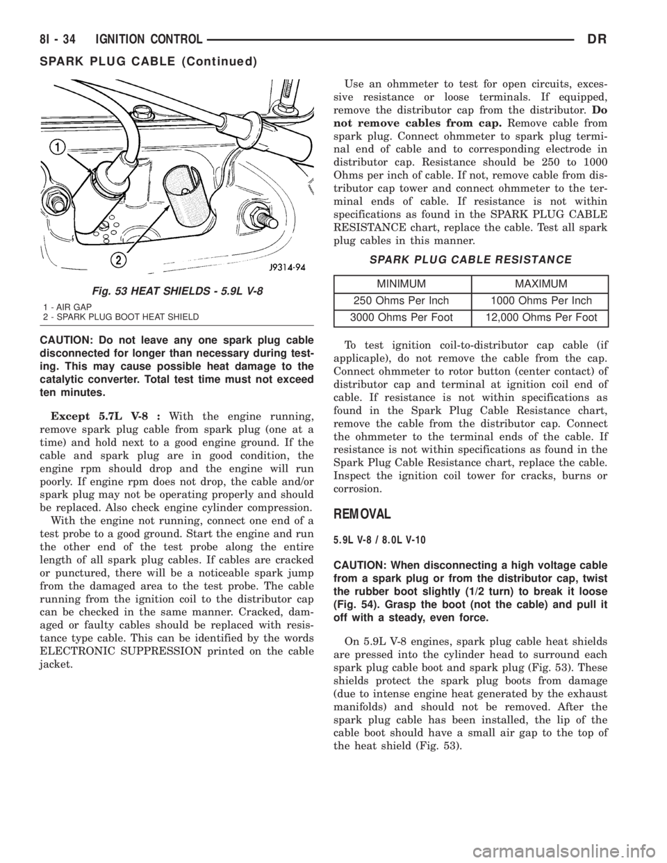
On 5.9L V-8 engines, spark plug cable heat shields
are pressed into the cylinder head to surround each
spark plug cable boot and spark plug (Fig. 53). These
shields protect the spark plug boots from damage
(due to intense engine heat generated by the exhaust
manifolds) and should not be removed. After the
spark plug cable has been installed, the lip of the
cable boot should have a small air gap to the top of
the heat shield (Fig. 53).
Fig. 53 HEAT SHIELDS - 5.9L V-8
1 - AIR GAP
2 - SPARK PLUG BOOT HEAT SHIELD
8I - 34 IGNITION CONTROLDR
SPARK PLUG CABLE (Continued)
Page 498 of 2895

the vehicle speed remains greater than about twenty-
four kilometers-per-hour (fifteen miles-per-hour).
²Vacuum Fluorescent Display Synchroniza-
tion- The EMIC transmits electronic panel lamp
dimming level messages which allows all other elec-
tronic modules on the PCI data bus with Vacuum
Fluorescent Display (VFD) units to coordinate their
illumination intensity with that of the EMIC VFD
units.
²Vehicle Theft Security System- The EMIC
monitors inputs from the door cylinder lock switch-
(es), the door ajar switches, the ignition switch, and
the Remote Keyless Entry (RKE) receiver module,
then provides electronic horn and lighting request
messages to the Front Control Module (FCM) located
on the Integrated Power Module (IPM) for the appro-
priate VTSS alarm output features.
²Wiper/Washer System Control- The EMIC
provides electronic wiper and/or washer request mes-
sages to the Front Control Module (FCM) located on
the Integrated Power Module (IPM) for the appropri-
ate wiper and washer system features. (Refer to 8 -
ELECTRICAL/WIPERS/WASHERS - DESCRIP-
TION).
The EMIC houses six analog gauges and has pro-
visions for up to twenty-three indicators (Fig. 3) or
(Fig. 4). The EMIC includes the following analog
gauges:
²Coolant Temperature Gauge
²Fuel Gauge
²Oil Pressure Gauge
²Speedometer
²Tachometer
²Voltage Gauge
Some of the EMIC indicators are automatically
configured when the EMIC is connected to the vehi-
cle electrical system for compatibility with certain
optional equipment or equipment required for regula-
tory purposes in certain markets. While each EMIC
may have provisions for indicators to support every
available option, the configurable indicators will not
be functional in a vehicle that does not have the
equipment that an indicator supports. The EMIC
includes provisions for the following indicators (Fig.
3) or (Fig. 4):
²Airbag Indicator (with Airbag System only)
²Antilock Brake System (ABS) Indicator
(with ABS or Rear Wheel Anti-Lock [RWAL]
brakes only)
²Brake Indicator
²Cargo Lamp Indicator
²Check Gauges Indicator
²Cruise Indicator (with Speed Control only)
²Door Ajar Indicator
²Electronic Throttle Control (ETC) Indicator
(with 5.7L Gasoline Engine only)²Gear Selector Indicator (with Automatic
Transmission only)
²High Beam Indicator
²Lamp Out Indicator
²Low Fuel Indicator
²Malfunction Indicator Lamp (MIL)
²Overdrive-Off Indicator (with Automatic
Transmission only)
²Seatbelt Indicator
²Security Indicator (with Sentry Key Immo-
bilizer & Vehicle Theft Security Systems only)
²Service Four-Wheel Drive Indicator (with
Four-Wheel Drive only)
²Transmission Overtemp Indicator (with
Automatic Transmission only)
²Turn Signal (Right and Left) Indicators
²Upshift Indicator (with Manual Transmis-
sion only)
²Washer Fluid Indicator
²Wait-To-Start Indicator (with Diesel Engine
only)
²Water-In-Fuel Indicator (with Diesel Engine
only)
Each indicator in the EMIC, except those located
within one of the VFD units, is illuminated by a ded-
icated LED that is soldered onto the EMIC electronic
circuit board. The LED units are not available for
service replacement and, if damaged or faulty, the
entire EMIC must be replaced. Cluster illumination
is accomplished by dimmable incandescent back
lighting, which illuminates the gauges for visibility
when the exterior lighting is turned on. Each of the
incandescent bulbs is secured by an integral bulb
holder to the electronic circuit board from the back of
the cluster housing.
Hard wired circuitry connects the EMIC to the
electrical system of the vehicle. These hard wired cir-
cuits are integral to several wire harnesses, which
are routed throughout the vehicle and retained by
many different methods. These circuits may be con-
nected to each other, to the vehicle electrical system
and to the EMIC through the use of a combination of
soldered splices, splice block connectors, and many
different types of wire harness terminal connectors
and insulators. Refer to the appropriate wiring infor-
mation. The wiring information includes wiring dia-
grams, proper wire and connector repair procedures,
further details on wire harness routing and reten-
tion, as well as pin-out and location views for the
various wire harness connectors, splices and grounds.
The EMIC modules for this model are serviced only
as complete units. The EMIC module cannot be
adjusted or repaired. If a gauge, an LED indicator, a
VFD unit, the electronic circuit board, the circuit
board hardware, the cluster overlay, or the EMIC
housing are damaged or faulty, the entire EMIC mod-
DRINSTRUMENT CLUSTER 8J - 5
INSTRUMENT CLUSTER (Continued)
Page 544 of 2895

STANDARD PROCEDURE
SAFETY PRECAUTIONS
WARNING: EYE PROTECTION SHOULD BE USED
WHEN SERVICING GLASS COMPONENTS. PER-
SONAL INJURY CAN RESULT.
CAUTION: Do not touch the glass of halogen bulbs
with fingers or other possibly oily surface, reduced
bulb life will result.Do not use bulbs with higher
candle power than indicated in the Bulb Application
table . Damage to lamp and/or Daytime Running
Lamp Module can result.Do not use fuses, circuit
breakers or relays having greater amperage value
than indicated on the fuse panel or in the Owners
Manual.
When it is necessary to remove components to ser-
vice another, it should not be necessary to apply
excessive force or bend a component to remove it.
Before damaging a trim component, verify hidden
fasteners or captured edges are not holding the com-
ponent in place.
SPECIFICATIONS
EXTERIOR LAMPS
CAUTION: Do not use bulbs that have a higher can-
dle power than the bulb listed in the Bulb Applica-
tion Table. Damage to lamp can result. Do not touch
halogen bulbs with fingers or other oily surfaces.
Bulb life will be reduced.
The following Bulb Application Table lists the lamp
title on the left side of the column and trade number
or part number on the right.
BULB APPLICATION TABLE
LAMP BULB
Back-up 3157
Center High Mounted
Stop lamp912
Fog lamp 9006LL
Front Park/Turn Signal 4157NAK
Head lamp 9007
License Plate 7F69
Tail, Brake, Turn Signal 3157
Side Marker, Tail Gate,
Cab Clearance168
SPECIAL TOOLS - HEADLAMP ALIGNMENT
BACKUP LAMP
REMOVAL
(1) Remove and isolate the negitive battery cable.
(2) Remove the taillamp unit (Refer to 8 - ELEC-
TRICAL/LAMPS/LIGHTING - EXTERIOR/TAIL
LAMP UNIT - REMOVAL).
(3) Remove the bulb back plate from the tail lamp
unit.
(4) Separate the bulb from the socket.
INSTALLATION
(1) Install the bulb into the socket.
(2) Install the bulb back plate to the tail lamp
unit.
(3) Install the tail lamp unit (Refer to 8 - ELEC-
TRICAL/LAMPS/LIGHTING - EXTERIOR/TAIL
LAMP UNIT - INSTALLATION).
(4) Reconnect the negative battery cable.
BACKUP LAMP SWITCH
DESCRIPTION
Vehicles equipped with a manual transmission
have a normally open, spring-loaded plunger type
back-up lamp switch (Fig. 1). The backup lamp
switch is located in a threaded hole on the side of the
manual transmission housing. The backup lamp
switch has a threaded body and a hex formation near
the plunger end of the switch, and an integral con-
nector at the opposite end of the switch. When
installed, only the connector and the hex formation
are visible on the outside of the transmission hous-
ing. Vehicles with an optional electronic automatic
transmission have a Transmission Range Sensor
(TRS) that is used to perform several functions,
including that of the backup lamp switch. The TRS is
described in further detail elsewhere in this service
information. The backup lamp switch cannot be
adjusted or repaired and, if faulty or damaged, the
entire switch unit must be replaced.
Headlamp Aiming Kit C-4466±A
DRLAMPS/LIGHTING - EXTERIOR 8L - 7
LAMPS/LIGHTING - EXTERIOR (Continued)
Page 595 of 2895
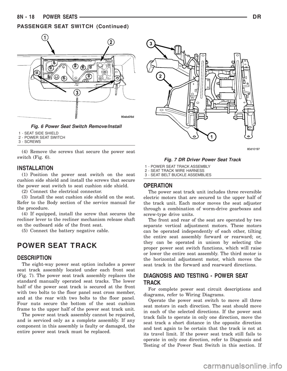
(4) Remove the screws that secure the power seat
switch (Fig. 6).
INSTALLATION
(1) Position the power seat switch on the seat
cushion side shield and install the screws that secure
the power seat switch to seat cushion side shield.
(2) Connect the electrical connector.
(3) Install the seat cushion side shield on the seat.
Refer to the Body section of the service manual for
the procedure.
(4) If equipped, install the screw that secures the
recliner lever to the recliner mechanism release shaft
on the outboard side of the front seat.
(5) Connect the battery negative cable.
POWER SEAT TRACK
DESCRIPTION
The eight-way power seat option includes a power
seat track assembly located under each front seat
(Fig. 7). The power seat track assembly replaces the
standard manually operated seat tracks. The lower
half of the power seat track is secured at the front
with two bolts to the floor panel seat cross member,
and at the rear with two bolts to the floor panel.
Four nuts secure the bottom of the seat cushion
frame to the upper half of the power seat track unit.
The power seat track assembly cannot be repaired,
and is serviced only as a complete assembly. If any
component in this assembly is faulty or damaged, the
entire power seat track must be replaced.
OPERATION
The power seat track unit includes three reversible
electric motors that are secured to the upper half of
the track unit. Each motor moves the seat adjuster
through a combination of worm-drive gearboxes and
screw-type drive units.
The front and rear of the seat are operated by two
separate vertical adjustment motors. These motors
can be operated independently of each other, tilting
the entire seat assembly forward or rearward; or,
they can be operated in unison by selecting the
proper power seat switch functions, which will raise
or lower the entire seat assembly. The third motor is
the horizontal adjustment motor, which moves the
seat track in the forward and rearward directions.
DIAGNOSIS AND TESTING - POWER SEAT
TRACK
For complete power seat circuit descriptions and
diagrams, refer to Wiring Diagrams.
Operate the power seat switch to move all three
seat motors in each direction. The seat should move
in each of the selected directions. If the power seat
track fails to operate in only one direction, move the
seat track a short distance in the opposite direction
and test again to be certain that the track is not at
its travel limit. If the power seat track still fails to
operate in only one direction, refer to Diagnosis and
Testing of the Power Seat Switch in this section. If
Fig. 6 Power Seat Switch Remove/Install
1 - SEAT SIDE SHIELD
2 - POWER SEAT SWITCH
3 - SCREWS
Fig. 7 DR Driver Power Seat Track
1 - POWER SEAT TRACK ASSEMBLY
2 - SEAT TRACK WIRE HARNESS
3 - SEAT BELT BUCKLE ASSEMBLIES
8N - 18 POWER SEATSDR
PASSENGER SEAT SWITCH (Continued)
Page 606 of 2895

Impact Airbag Control Modules (SIACM). An airbag
indicator in the ElectroMechanical Instrument Clus-
ter (EMIC) illuminates for about six seconds as a
bulb test each time the ignition switch is turned to
the On or Start positions. Following the bulb test,
the airbag indicator is turned on or off by the ACM
to indicate the status of the supplemental restraint
system. If the airbag indicator comes on at any time
other than during the bulb test, it indicates that
there is a problem in the supplemental restraint sys-
tem electrical circuits. Such a problem may cause air-
bags not to deploy when required, or to deploy when
not required.
Deployment of the supplemental restraints
depends upon the angle and severity of an impact.
Deployment is not based upon vehicle speed; rather,
deployment is based upon the rate of deceleration as
measured by the forces of gravity (G force) upon the
impact sensors. When an impact is severe enough,
the microprocessor in the ACM or the SIACM signals
the inflator of the appropriate airbag units to deploy
their airbag cushions. The outboard front seat belt
tensioners are provided with a deployment signal by
the ACM in conjunction with the driver and passen-
ger airbags. During a frontal vehicle impact, the
knee blockers work in concert with properly fastened
and adjusted seat belts to restrain both the driver
and the front seat passenger in the proper position
for an airbag deployment. The knee blockers also
absorb and distribute the crash energy from the
driver and the front seat passenger to the structure
of the instrument panel. The seat belt tensioner
removes the slack from the outboard front seat belts
to provide further assurance that the driver and
front seat passenger are properly positioned and
restrained for an airbag deployment.
Typically, the vehicle occupants recall more about
the events preceding and following a collision than
they do of an airbag deployment itself. This is
because the airbag deployment and deflation occur so
rapidly. In a typical 48 kilometer-per-hour (30 mile-
per-hour) barrier impact, from the moment of impact
until the airbags are fully inflated takes about 40
milliseconds. Within one to two seconds from the
moment of impact, the airbags are almost entirely
deflated. The times cited for these events are approx-
imations, which apply only to a barrier impact at the
given speed. Actual times will vary somewhat,
depending upon the vehicle speed, impact angle,
severity of the impact, and the type of collision.When the ACM monitors a problem in any of the
dual front airbag system circuits or components,
including the seat belt tensioners, it stores a fault
code or Diagnostic Trouble Code (DTC) in its memory
circuit and sends an electronic message to the EMIC
to turn on the airbag indicator. When the SIACM
monitors a problem in any of the side curtain airbag
system circuits or component, it stores a fault code or
DTC in its memory circuit and sends an electronic
message to the ACM, and the ACM sends an elec-
tronic message to the EMIC to turn on the airbag
indicator. Proper testing of the supplemental
restraint system components, the Programmable
Communications Interface (PCI) data bus, the elec-
tronic message inputs to and outputs from the EMIC,
the SIACM, or the ACM, as well as the retrieval or
erasure of a DTC from the ACM, SIACM, or EMIC
requires the use of a DRBIIItscan tool. Refer to the
appropriate diagnostic information.
See the owner's manual in the vehicle glove box for
more information on the features, use and operation
of all of the factory-installed passive restraints.
WARNING
WARNINGS - RESTRAINT SYSTEM
WARNING: DURING AND FOLLOWING ANY SEAT
BELT OR CHILD RESTRAINT ANCHOR SERVICE,
CAREFULLY INSPECT ALL SEAT BELTS, BUCKLES,
MOUNTING HARDWARE, RETRACTORS, TETHER
STRAPS, AND ANCHORS FOR PROPER INSTALLA-
TION, OPERATION, OR DAMAGE. REPLACE ANY
BELT THAT IS CUT, FRAYED, OR TORN.
STRAIGHTEN ANY BELT THAT IS TWISTED.
TIGHTEN ANY LOOSE FASTENERS. REPLACE ANY
BELT THAT HAS A DAMAGED OR INOPERATIVE
BUCKLE OR RETRACTOR. REPLACE ANY BELT
THAT HAS A BENT OR DAMAGED LATCH PLATE
OR ANCHOR PLATE. REPLACE ANY CHILD
RESTRAINT ANCHOR OR THE UNIT TO WHICH THE
ANCHOR IS INTEGRAL THAT HAS BEEN BENT OR
DAMAGED. NEVER ATTEMPT TO REPAIR A SEAT
BELT OR CHILD RESTRAINT COMPONENT.
ALWAYS REPLACE DAMAGED OR FAULTY SEAT
BELT AND CHILD RESTRAINT COMPONENTS WITH
THE CORRECT, NEW AND UNUSED REPLACEMENT
PARTS LISTED IN THE DAIMLERCHRYSLER MOPAR
PARTS CATALOG.
DRRESTRAINTS 8O - 5
RESTRAINTS (Continued)
Page 614 of 2895
the locating pins on the bottom of the ACM mounting
flanges into the locating holes in the bracket.
(3) Still working from the left side of the floor
panel transmission tunnel, install and tighten the
two screws that secure the left ACM mounting
flanges to the bracket that is welded onto the floor
panel transmission tunnel. Tighten the screws to 14
N´m (10 ft. lbs.).
(4) From the right side of the floor panel transmis-
sion tunnel, tighten each of the two screws that
secure the right side of the ACM to the bracket on
the floor panel transmission tunnel. Tighten the
screws to 14 N´m (10 ft. lbs.).
(5) Reach through the rearward facing opening
below the instrument panel center stack support
bracket on the top of the floor panel transmission
tunnel to access and reconnect the instrument panel
wire harness connector for the ACM to the ACM con-
nector receptacle located on the rearward facing side
of the module. Be certain that the latch and the red
Connector Position Assurance (CPA) lock on the con-
nector are each fully engaged.
(6) On models with an automatic transmission,
reinstall the ACM cover onto the instrument panel.
(Refer to 8 - ELECTRICAL/RESTRAINTS/ACM
COVER - INSTALLATION).
(7) On models with a manual transmission, rein-
stall the floor console onto the top of the floor panel
transmission tunnel. (Refer to 23 - BODY/INTERI-
OR/FLOOR CONSOLE - INSTALLATION).
(8) Do not reconnect the battery negative cable at
this time. The supplemental restraint system verifi-
cation test procedure should be performed following
service of any supplemental restraint system compo-
nent. (Refer to 8 - ELECTRICAL/RESTRAINTS -
STANDARD PROCEDURE - VERIFICATION TEST).AUTOMATIC LOCKING
RETRACTOR
DESCRIPTION
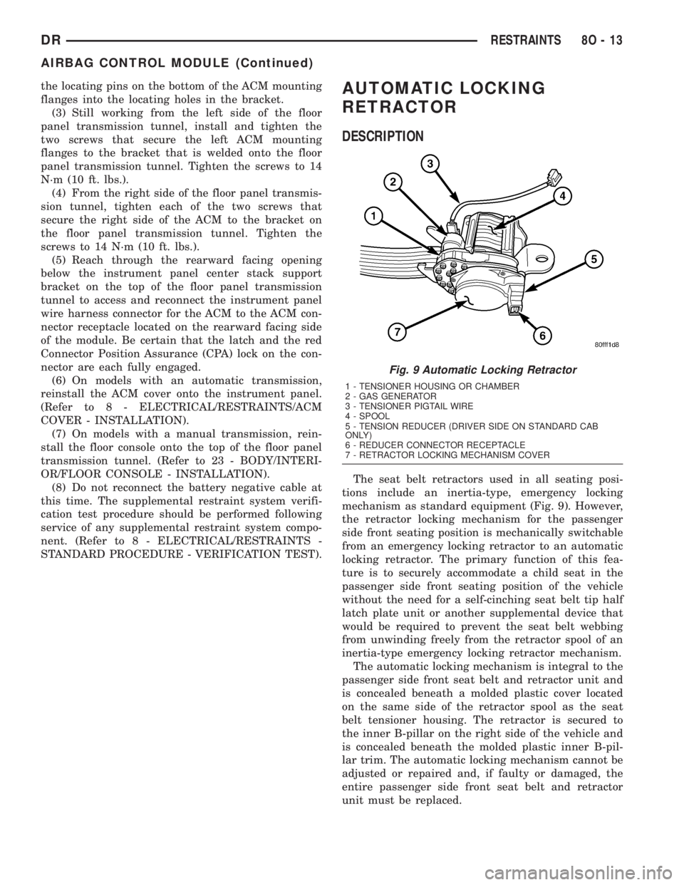
The seat belt retractors used in all seating posi-
tions include an inertia-type, emergency locking
mechanism as standard equipment (Fig. 9). However,
the retractor locking mechanism for the passenger
side front seating position is mechanically switchable
from an emergency locking retractor to an automatic
locking retractor. The primary function of this fea-
ture is to securely accommodate a child seat in the
passenger side front seating position of the vehicle
without the need for a self-cinching seat belt tip half
latch plate unit or another supplemental device that
would be required to prevent the seat belt webbing
from unwinding freely from the retractor spool of an
inertia-type emergency locking retractor mechanism.
The automatic locking mechanism is integral to the
passenger side front seat belt and retractor unit and
is concealed beneath a molded plastic cover located
on the same side of the retractor spool as the seat
belt tensioner housing. The retractor is secured to
the inner B-pillar on the right side of the vehicle and
is concealed beneath the molded plastic inner B-pil-
lar trim. The automatic locking mechanism cannot be
adjusted or repaired and, if faulty or damaged, the
entire passenger side front seat belt and retractor
unit must be replaced.
Fig. 9 Automatic Locking Retractor
1 - TENSIONER HOUSING OR CHAMBER
2 - GAS GENERATOR
3 - TENSIONER PIGTAIL WIRE
4 - SPOOL
5 - TENSION REDUCER (DRIVER SIDE ON STANDARD CAB
ONLY)
6 - REDUCER CONNECTOR RECEPTACLE
7 - RETRACTOR LOCKING MECHANISM COVER
DRRESTRAINTS 8O - 13
AIRBAG CONTROL MODULE (Continued)
Page 667 of 2895
(8) Connect servo cable to throttle body. Refer to
servo Cable Removal/Installation.
(9) Install left-front wheel-well liner.
(10) Connect negative battery cable to battery
(connect both cables if diesel).
(11) Before starting engine, operate accelerator
pedal to check for any binding.
SWITCH
DESCRIPTION
Two separate switch pods operate the speed control
system. The steering-wheel-mounted switches use
multiplexed circuits to provide inputs to the PCM (to
the ECM for diesel) for ON, OFF, RESUME, ACCEL-
ERATE, SET, DECEL and CANCEL modes. Refer to
the owner's manual for more information on speed
control switch functions and setting procedures.
The individual switches cannot be repaired. If one
switch fails, the entire switch module must be
replaced.
Depending on engine control computer (JTEC
having a 3± plug connector or NGC having a 4±
plug connector), 2 types of switches are used.
Both types of switches are internally and exter-
nally different. The switch used with the NGC
system has an attached pigtail lead. The switch
used with the JTEC system does not have an
attached pigtail lead.
OPERATION
When speed control is selected by depressing the
ON, OFF switch, the PCM (ECM for diesel) allows a
set speed to be stored in its RAM for speed control.
To store a set speed, depress the SET switch while
the vehicle is moving at a speed between approxi-
mately 35 and 85 mph. In order for the speed control
to engage, the brakes cannot be applied, nor can the
gear selector be indicating the transmission is in
Park or Neutral.
The speed control can be disengaged manually by:
²Stepping on the brake pedal
²Depressing the OFF switch
²Depressing the CANCEL switch.
The speed control can be disengaged also by any of
the following conditions:
²An indication of Park or Neutral
²The VSS signal increases at a rate of 10 mph
per second (indicates that the co-efficient of friction
between the road surface and tires is extremely low)
²Depressing the clutch pedal.
²Excessive engine rpm (indicates that the trans-
mission may be in a low gear)
²The VSS signal decreases at a rate of 10 mph
per second (indicates that the vehicle may have
decelerated at an extremely high rate)
²If the actual speed is not within 20 mph of the
set speed
The previous disengagement conditions are pro-
grammed for added safety.
Once the speed control has been disengaged,
depressing the ACCEL switch restores the vehicle to
the target speed that was stored in the PCM's RAM
(ECM for diesel).
NOTE: Depressing the OFF switch will erase the set
speed stored in the PCM's RAM.
If, while the speed control is engaged, the driver
wishes to increase vehicle speed, the PCM (ECM for
diesel) is programmed for an acceleration feature.
With the ACCEL switch held closed, the vehicle
accelerates slowly to the desired speed. The new tar-
get speed is stored in the PCM's RAM when the
ACCEL switch is released. The PCM also has a9tap-
up9feature in which vehicle speed increases at a rate
of approximately 2 mph for each momentary switch
activation of the ACCEL switch.
The PCM also provides a means to decelerate with-
out disengaging speed control. To decelerate from an
existing recorded target speed, depress and hold the
COAST switch until the desired speed is reached.
Then release the switch. The ON, OFF switch oper-
ates two components: the PCM's ON, OFF input, and
the battery voltage to the brake switch.
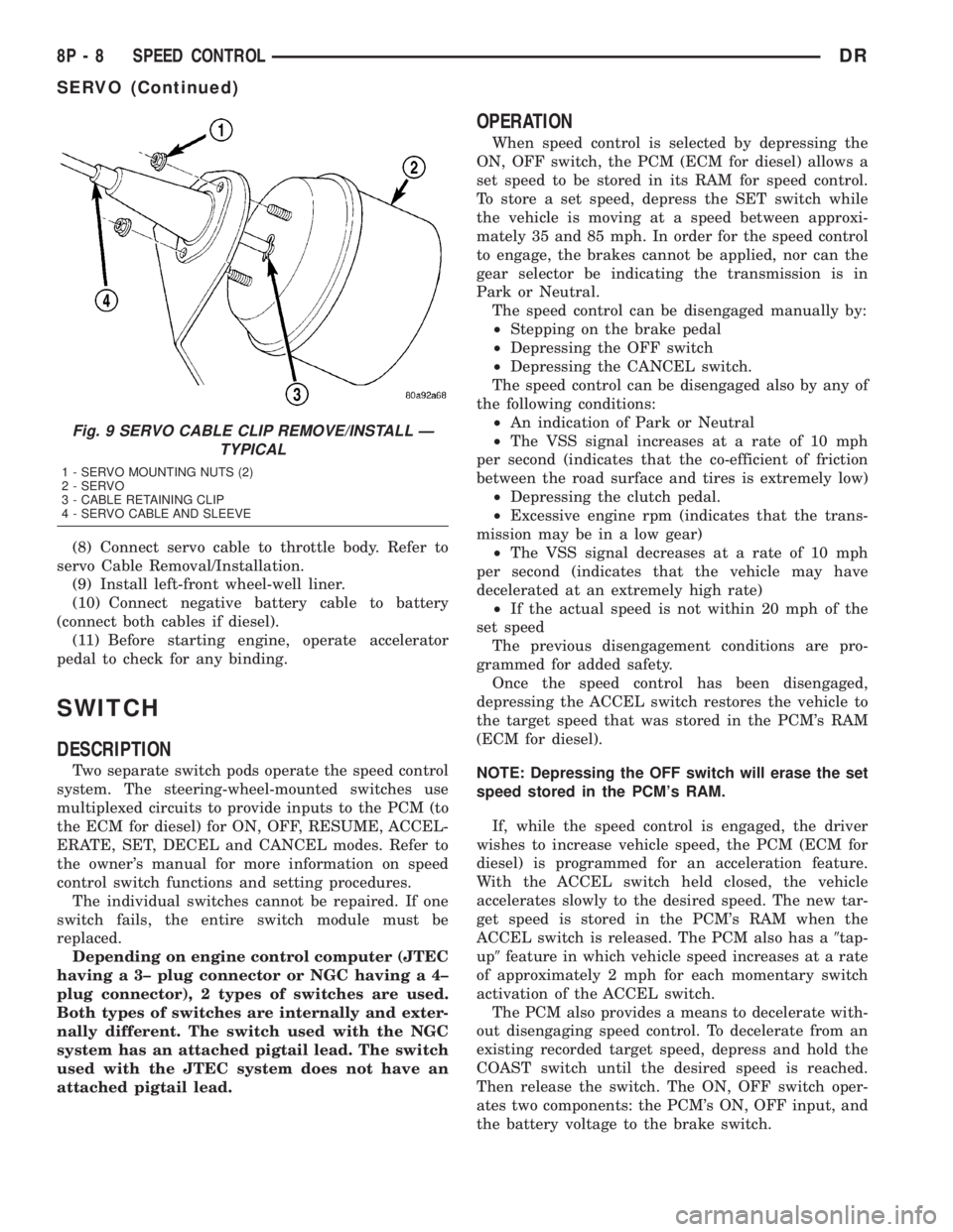
Fig. 9 SERVO CABLE CLIP REMOVE/INSTALL Ð
TYPICAL
1 - SERVO MOUNTING NUTS (2)
2 - SERVO
3 - CABLE RETAINING CLIP
4 - SERVO CABLE AND SLEEVE
8P - 8 SPEED CONTROLDR
SERVO (Continued)
Page 688 of 2895
(4) Reinstall the washer hose for the washer noz-
zle into its routing clips on the underside of the cowl
plenum cover/grille panel.
(5) Reinstall the cowl plenum cover/grille panel
over the cowl plenum. (Refer to 23 - BODY/EXTERI-
OR/COWL GRILLE - INSTALLATION).
(6) Close and latch the hood.
(7) Reinstall both wiper arms onto the wiper piv-
ots. (Refer to 8 - ELECTRICAL/WIPERS/WASHERS/
WIPER ARM - INSTALLATION).
WASHER PUMP/MOTOR
DESCRIPTION
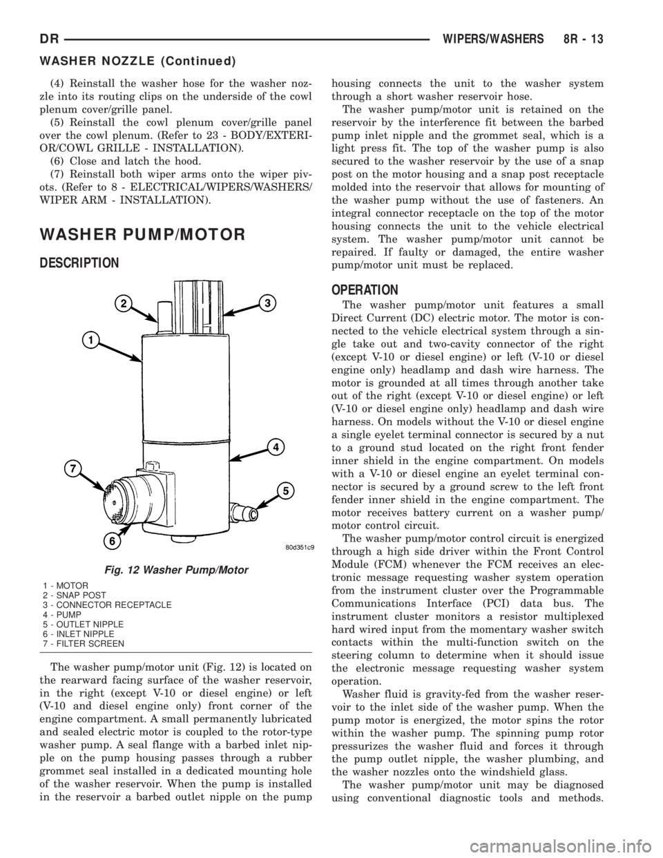
The washer pump/motor unit (Fig. 12) is located on
the rearward facing surface of the washer reservoir,
in the right (except V-10 or diesel engine) or left
(V-10 and diesel engine only) front corner of the
engine compartment. A small permanently lubricated
and sealed electric motor is coupled to the rotor-type
washer pump. A seal flange with a barbed inlet nip-
ple on the pump housing passes through a rubber
grommet seal installed in a dedicated mounting hole
of the washer reservoir. When the pump is installed
in the reservoir a barbed outlet nipple on the pumphousing connects the unit to the washer system
through a short washer reservoir hose.
The washer pump/motor unit is retained on the
reservoir by the interference fit between the barbed
pump inlet nipple and the grommet seal, which is a
light press fit. The top of the washer pump is also
secured to the washer reservoir by the use of a snap
post on the motor housing and a snap post receptacle
molded into the reservoir that allows for mounting of
the washer pump without the use of fasteners. An
integral connector receptacle on the top of the motor
housing connects the unit to the vehicle electrical
system. The washer pump/motor unit cannot be
repaired. If faulty or damaged, the entire washer
pump/motor unit must be replaced.
OPERATION
The washer pump/motor unit features a small
Direct Current (DC) electric motor. The motor is con-
nected to the vehicle electrical system through a sin-
gle take out and two-cavity connector of the right
(except V-10 or diesel engine) or left (V-10 or diesel
engine only) headlamp and dash wire harness. The
motor is grounded at all times through another take
out of the right (except V-10 or diesel engine) or left
(V-10 or diesel engine only) headlamp and dash wire
harness. On models without the V-10 or diesel engine
a single eyelet terminal connector is secured by a nut
to a ground stud located on the right front fender
inner shield in the engine compartment. On models
with a V-10 or diesel engine an eyelet terminal con-
nector is secured by a ground screw to the left front
fender inner shield in the engine compartment. The
motor receives battery current on a washer pump/
motor control circuit.
The washer pump/motor control circuit is energized
through a high side driver within the Front Control
Module (FCM) whenever the FCM receives an elec-
tronic message requesting washer system operation
from the instrument cluster over the Programmable
Communications Interface (PCI) data bus. The
instrument cluster monitors a resistor multiplexed
hard wired input from the momentary washer switch
contacts within the multi-function switch on the
steering column to determine when it should issue
the electronic message requesting washer system
operation.
Washer fluid is gravity-fed from the washer reser-
voir to the inlet side of the washer pump. When the
pump motor is energized, the motor spins the rotor
within the washer pump. The spinning pump rotor
pressurizes the washer fluid and forces it through
the pump outlet nipple, the washer plumbing, and
the washer nozzles onto the windshield glass.
The washer pump/motor unit may be diagnosed
using conventional diagnostic tools and methods.
Fig. 12 Washer Pump/Motor
1 - MOTOR
2 - SNAP POST
3 - CONNECTOR RECEPTACLE
4 - PUMP
5 - OUTLET NIPPLE
6 - INLET NIPPLE
7 - FILTER SCREEN
DRWIPERS/WASHERS 8R - 13
WASHER NOZZLE (Continued)