2003 DODGE RAM tire type
[x] Cancel search: tire typePage 175 of 2895

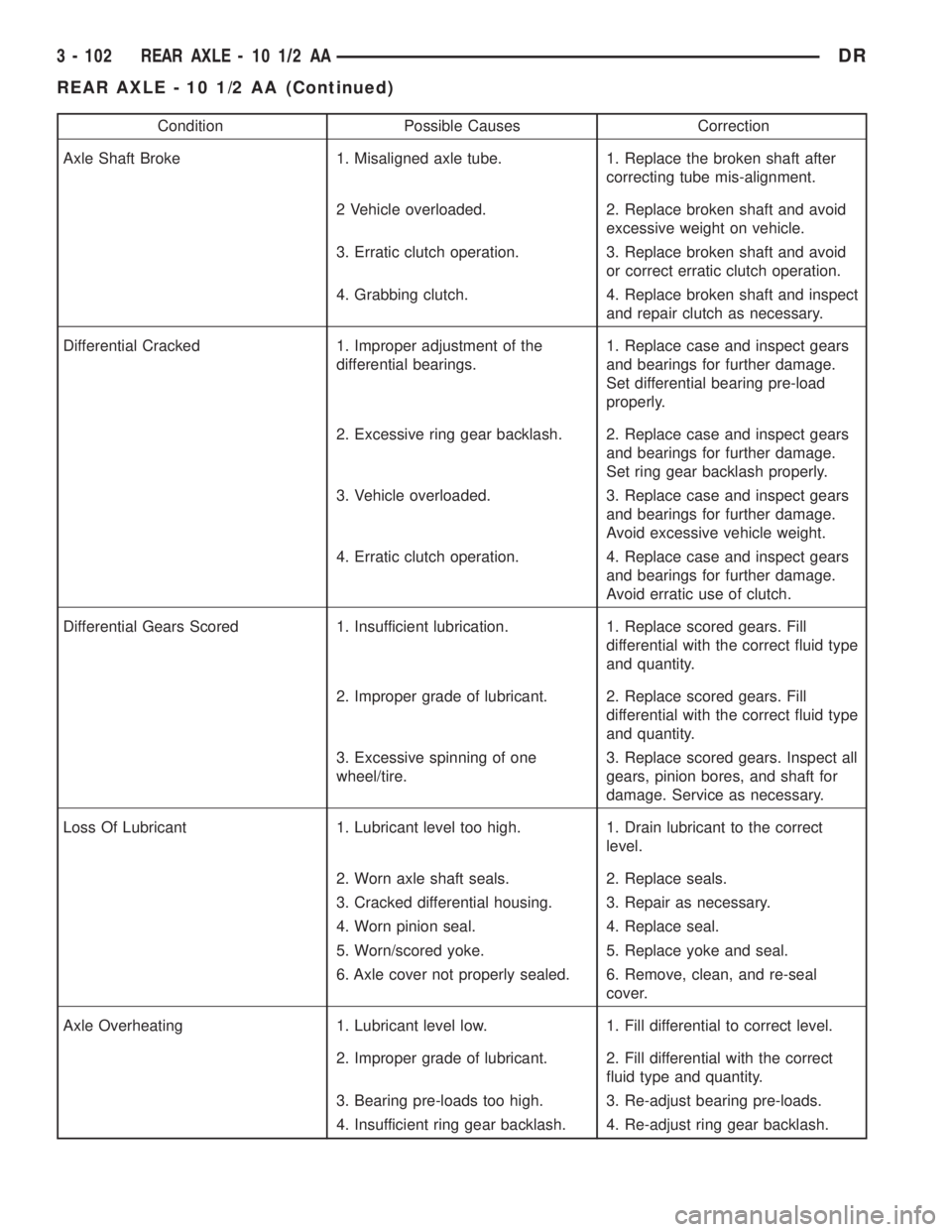
Condition Possible Causes Correction
Axle Shaft Broke 1. Misaligned axle tube. 1. Replace the broken shaft after
correcting tube mis-alignment.
2 Vehicle overloaded. 2. Replace broken shaft and avoid
excessive weight on vehicle.
3. Erratic clutch operation. 3. Replace broken shaft and avoid
or correct erratic clutch operation.
4. Grabbing clutch. 4. Replace broken shaft and inspect
and repair clutch as necessary.
Differential Cracked 1. Improper adjustment of the
differential bearings.1. Replace case and inspect gears
and bearings for further damage.
Set differential bearing pre-load
properly.
2. Excessive ring gear backlash. 2. Replace case and inspect gears
and bearings for further damage.
Set ring gear backlash properly.
3. Vehicle overloaded. 3. Replace case and inspect gears
and bearings for further damage.
Avoid excessive vehicle weight.
4. Erratic clutch operation. 4. Replace case and inspect gears
and bearings for further damage.
Avoid erratic use of clutch.
Differential Gears Scored 1. Insufficient lubrication. 1. Replace scored gears. Fill
differential with the correct fluid type
and quantity.
2. Improper grade of lubricant. 2. Replace scored gears. Fill
differential with the correct fluid type
and quantity.
3. Excessive spinning of one
wheel/tire.3. Replace scored gears. Inspect all
gears, pinion bores, and shaft for
damage. Service as necessary.
Loss Of Lubricant 1. Lubricant level too high. 1. Drain lubricant to the correct
level.
2. Worn axle shaft seals. 2. Replace seals.
3. Cracked differential housing. 3. Repair as necessary.
4. Worn pinion seal. 4. Replace seal.
5. Worn/scored yoke. 5. Replace yoke and seal.
6. Axle cover not properly sealed. 6. Remove, clean, and re-seal
cover.
Axle Overheating 1. Lubricant level low. 1. Fill differential to correct level.
2. Improper grade of lubricant. 2. Fill differential with the correct
fluid type and quantity.
3. Bearing pre-loads too high. 3. Re-adjust bearing pre-loads.
4. Insufficient ring gear backlash. 4. Re-adjust ring gear backlash.
3 - 102 REAR AXLE - 10 1/2 AADR
REAR AXLE - 10 1/2 AA (Continued)
Page 176 of 2895

Condition Possible Causes Correction
Gear Teeth Broke 1. Overloading. 1. Replace gears. Examine other
gears and bearings for possible
damage.
2. Erratic clutch operation. 2. Replace gears and examine the
remaining parts for damage. Avoid
erratic clutch operation.
3. Ice-spotted pavement. 3. Replace gears and examine
remaining parts for damage.
4. Improper adjustments. 4. Replace gears and examine
remaining parts for damage. Ensure
ring gear backlash is correct.
Axle Noise 1. Insufficient lubricant. 1. Fill differential with the correct
fluid type and quantity.
2. Improper ring gear and pinion
adjustment.2. Check ring gear and pinion
contact pattern. Adjust backlash or
pinion depth.
3. Unmatched ring gear and pinion. 3. Replace gears with a matched
ring gear and pinion.
4. Worn teeth on ring gear and/or
pinion.4. Replace ring gear and pinion.
5. Loose pinion bearings. 5. Adjust pinion bearing pre-load.
6. Loose differential bearings. 6. Adjust differential bearing
pre-load.
7. Mis-aligned or sprung ring gear. 7. Measure ring gear run-out.
Replace components as necessary.
8. Loose differential bearing cap
bolts.8. Inspect differential components
and replace as necessary. Ensure
that the bearing caps are torqued
tot he proper specification.
9. Housing not machined properly. 9. Replace housing.
REMOVAL
(1) Raise and support the vehicle.
(2) Position a lifting device under the axle.
(3) Secure axle to device.
(4) Remove wheels and tires assemblies.
(5) Remove RWAL sensor from the differential
housing.
(6) Remove brake hose at the axle junction block
and axle vent hose.
(7) Disconnect parking brake cables and cable
brackets.
(8) Remove brake calipers and rotors.
(9) Mark propeller shaft and companion flange for
installation alignment reference.
(10) Remove propeller shaft.
(11) Remove shock absorbers from axle.
(12) Remove U-bolts from axle.
(13) Separate the axle from the vehicle.
INSTALLATION
(1) Raise axle with lifting device and align to the
leaf spring centering bolts.
(2) Install axle U-bolts and tighten to 149 N´m
(110 ft. lbs.).
(3) Install shock absorbers to axle and tighten to
specification.
(4) Install the RWAL sensor to the differential
housing.
(5) Connect the parking brake cables and cable
brackets.
(6) Install brake calipers.
(7) Connect brake hose to the axle junction block
and axle vent hose.
(8) Align propeller shaft and pinion companion
flange reference marks and tighten companion flange
bolts to 115 N´m (85 ft. lbs.).
(9) Install the wheels and tires.
DRREAR AXLE - 10 1/2 AA 3 - 103
REAR AXLE - 10 1/2 AA (Continued)
Page 202 of 2895

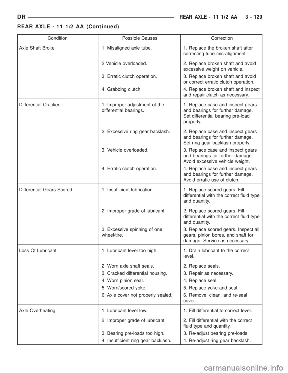
Condition Possible Causes Correction
Axle Shaft Broke 1. Misaligned axle tube. 1. Replace the broken shaft after
correcting tube mis-alignment.
2 Vehicle overloaded. 2. Replace broken shaft and avoid
excessive weight on vehicle.
3. Erratic clutch operation. 3. Replace broken shaft and avoid
or correct erratic clutch operation.
4. Grabbing clutch. 4. Replace broken shaft and inspect
and repair clutch as necessary.
Differential Cracked 1. Improper adjustment of the
differential bearings.1. Replace case and inspect gears
and bearings for further damage.
Set differential bearing pre-load
properly.
2. Excessive ring gear backlash. 2. Replace case and inspect gears
and bearings for further damage.
Set ring gear backlash properly.
3. Vehicle overloaded. 3. Replace case and inspect gears
and bearings for further damage.
Avoid excessive vehicle weight.
4. Erratic clutch operation. 4. Replace case and inspect gears
and bearings for further damage.
Avoid erratic use of clutch.
Differential Gears Scored 1. Insufficient lubrication. 1. Replace scored gears. Fill
differential with the correct fluid type
and quantity.
2. Improper grade of lubricant. 2. Replace scored gears. Fill
differential with the correct fluid type
and quantity.
3. Excessive spinning of one
wheel/tire.3. Replace scored gears. Inspect all
gears, pinion bores, and shaft for
damage. Service as necessary.
Loss Of Lubricant 1. Lubricant level too high. 1. Drain lubricant to the correct
level.
2. Worn axle shaft seals. 2. Replace seals.
3. Cracked differential housing. 3. Repair as necessary.
4. Worn pinion seal. 4. Replace seal.
5. Worn/scored yoke. 5. Replace yoke and seal.
6. Axle cover not properly sealed. 6. Remove, clean, and re-seal
cover.
Axle Overheating 1. Lubricant level low. 1. Fill differential to correct level.
2. Improper grade of lubricant. 2. Fill differential with the correct
fluid type and quantity.
3. Bearing pre-loads too high. 3. Re-adjust bearing pre-loads.
4. Insufficient ring gear backlash. 4. Re-adjust ring gear backlash.
DRREAR AXLE - 11 1/2 AA 3 - 129
REAR AXLE - 11 1/2 AA (Continued)
Page 203 of 2895

Condition Possible Causes Correction
Gear Teeth Broke 1. Overloading. 1. Replace gears. Examine other
gears and bearings for possible
damage.
2. Erratic clutch operation. 2. Replace gears and examine the
remaining parts for damage. Avoid
erratic clutch operation.
3. Ice-spotted pavement. 3. Replace gears and examine
remaining parts for damage.
4. Improper adjustments. 4. Replace gears and examine
remaining parts for damage. Ensure
ring gear backlash is correct.
Axle Noise 1. Insufficient lubricant. 1. Fill differential with the correct
fluid type and quantity.
2. Improper ring gear and pinion
adjustment.2. Check ring gear and pinion
contact pattern. Adjust backlash or
pinion depth.
3. Unmatched ring gear and pinion. 3. Replace gears with a matched
ring gear and pinion.
4. Worn teeth on ring gear and/or
pinion.4. Replace ring gear and pinion.
5. Loose pinion bearings. 5. Adjust pinion bearing pre-load.
6. Loose differential bearings. 6. Adjust differential bearing
pre-load.
7. Mis-aligned or sprung ring gear. 7. Measure ring gear run-out.
Replace components as necessary.
8. Loose differential bearing cap
bolts.8. Inspect differential components
and replace as necessary. Ensure
that the bearing caps are torqued
tot he proper specification.
9. Housing not machined properly. 9. Replace housing.
REMOVAL
(1) Raise and support the vehicle.
(2) Position a lifting device under the axle.
(3) Secure axle to device.
(4) Remove wheels and tires assemblies.
(5) Remove RWAL sensor from the differential
housing.
(6) Remove brake hose at the axle junction block
and axle vent hose.
(7) Disconnect parking brake cables and cable
brackets.
(8) Remove brake calipers.
(9) Mark propeller shaft and companion flange for
installation alignment reference.
(10) Remove propeller shaft.
(11) Remove shock absorbers from axle.
(12) Remove U-bolets from axle.
(13) Separate the axle from the vehicle.
INSTALLATION
(1) Raise axle with lifting device and align to the
leaf spring centering bolts.
(2) Install axle U-bolts and tighten to 149 N´m
(110 ft. lbs.).
(3) Install shock absorbers to axle and tighten to
specification.
(4) Install the RWAL sensor to the differential
housing.
(5) Connect the parking brake cables and cable
brackets.
(6) Connect brake hose to the axle junction block
and axle vent hose.
(7) Align propeller shaft and pinion companion
flange reference marks and tighten companion flange
bolts to 115 N´m (85 ft. lbs.).
(8) Install the wheels and tires.
(9) Fill differential to specifications.
3 - 130 REAR AXLE - 11 1/2 AADR
REAR AXLE - 11 1/2 AA (Continued)
Page 238 of 2895

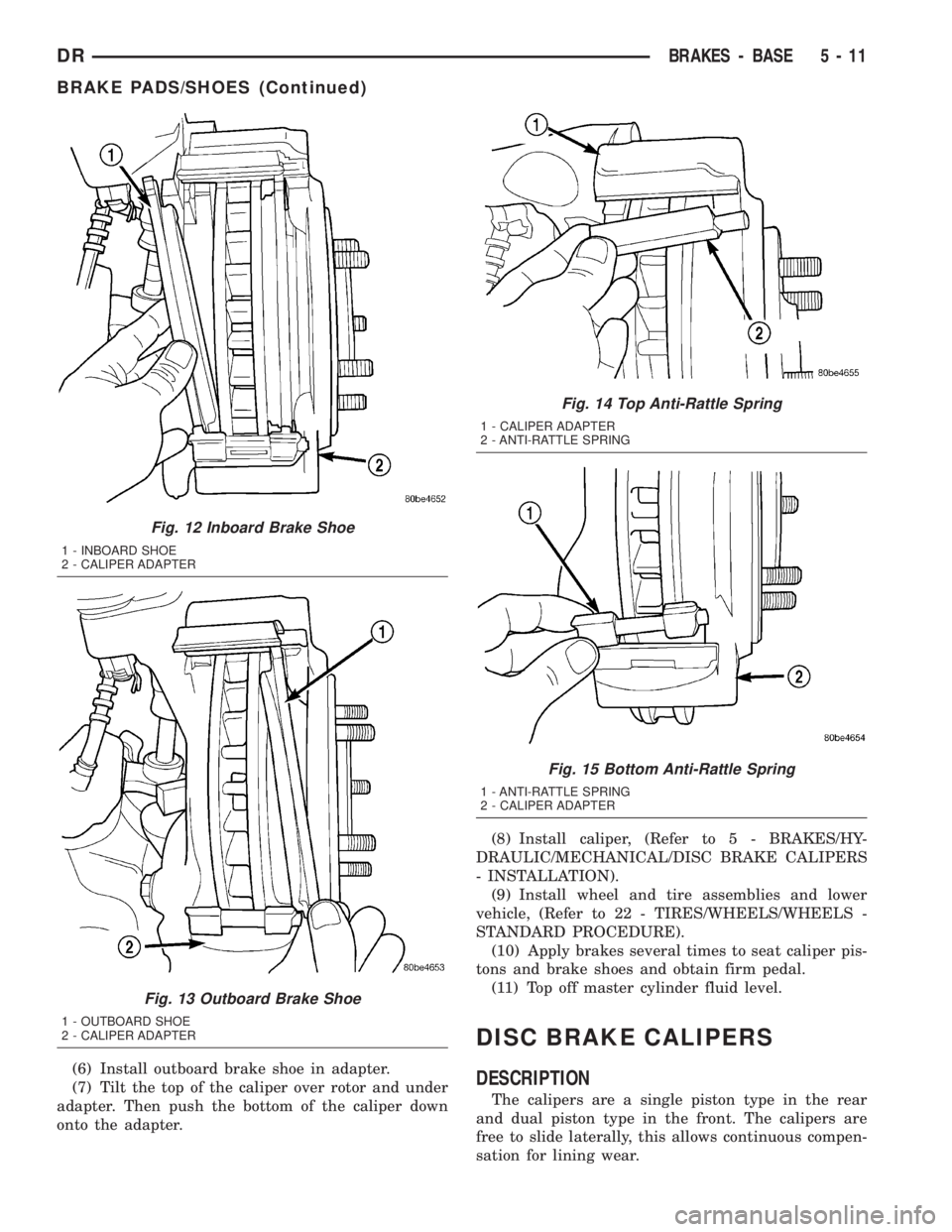
(6) Install outboard brake shoe in adapter.
(7) Tilt the top of the caliper over rotor and under
adapter. Then push the bottom of the caliper down
onto the adapter.(8) Install caliper, (Refer to 5 - BRAKES/HY-
DRAULIC/MECHANICAL/DISC BRAKE CALIPERS
- INSTALLATION).
(9) Install wheel and tire assemblies and lower
vehicle, (Refer to 22 - TIRES/WHEELS/WHEELS -
STANDARD PROCEDURE).
(10) Apply brakes several times to seat caliper pis-
tons and brake shoes and obtain firm pedal.
(11) Top off master cylinder fluid level.
DISC BRAKE CALIPERS
DESCRIPTION
The calipers are a single piston type in the rear
and dual piston type in the front. The calipers are
free to slide laterally, this allows continuous compen-
sation for lining wear.
Fig. 12 Inboard Brake Shoe
1 - INBOARD SHOE
2 - CALIPER ADAPTER
Fig. 13 Outboard Brake Shoe
1 - OUTBOARD SHOE
2 - CALIPER ADAPTER
Fig. 14 Top Anti-Rattle Spring
1 - CALIPER ADAPTER
2 - ANTI-RATTLE SPRING
Fig. 15 Bottom Anti-Rattle Spring
1 - ANTI-RATTLE SPRING
2 - CALIPER ADAPTER
DRBRAKES - BASE 5 - 11
BRAKE PADS/SHOES (Continued)
Page 245 of 2895

(6) Adjust brake shoes to drum with brake gauge
(Refer to 5 - BRAKES/PARKING BRAKE/SHOES -
ADJUSTMENTS).
(7) Install the rotor (Refer to 5 - BRAKES/HY-
DRAULIC/MECHANICAL/ROTORS - INSTALLA-
TION).
(8) Install the caliper adapter (Refer to 5 -
BRAKES/HYDRAULIC/MECHANICAL/DISC
BRAKE CALIPER ADAPTER - INSTALLATION).
(9) Install the caliper (Refer to 5 - BRAKES/HY-
DRAULIC/MECHANICAL/DISC BRAKE CALIPERS
- INSTALLATION).
(10) Install wheel and tire assembly.
FLUID
DIAGNOSIS AND TESTING - BRAKE FLUID
CONTAMINATION
Indications of fluid contamination are swollen or
deteriorated rubber parts.
Swollen rubber parts indicate the presence of
petroleum in the brake fluid.
To test for contamination, put a small amount of
drained brake fluid in clear glass jar. If fluid sepa-
rates into layers, there is mineral oil or other fluid
contamination of the brake fluid.
If brake fluid is contaminated, drain and thor-
oughly flush system. Replace master cylinder, propor-
tioning valve, caliper seals, wheel cylinder seals,
Antilock Brakes hydraulic unit and all hydraulic
fluid hoses.
STANDARD PROCEDURE - BRAKE FLUID
LEVEL
Always clean the master cylinder reservoir and
caps before checking fluid level. If not cleaned, dirt
could enter the fluid.
The fluid fill level is indicated on the side of the
master cylinder reservoir (Fig. 33).
The correct fluid level is to the MAX indicator on
the side of the reservoir. If necessary, add fluid to the
proper level.
SPECIFICATIONS
BRAKE FLUID
The brake fluid used in this vehicle must conform
to DOT 3 specifications and SAE J1703 standards.
No other type of brake fluid is recommended or
approved for usage in the vehicle brake system. Use
only Mopar brake fluid or an equivalent from a
tightly sealed container.
CAUTION: Never use reclaimed brake fluid or fluid
from an container which has been left open. An
open container of brake fluid will absorb moisture
from the air and contaminate the fluid.
CAUTION: Never use any type of a petroleum-based
fluid in the brake hydraulic system. Use of such
type fluids will result in seal damage of the vehicle
brake hydraulic system causing a failure of the
vehicle brake system. Petroleum based fluids would
be items such as engine oil, transmission fluid,
power steering fluid, etc.
Fig. 32 CALIPER ADAPTER MOUNT - REAR
1 - CALIPER ADAPTER MOUNT
2 - AXLE TUBE
3 - MOUNTING STUDS
Fig. 33 FLUID LEVEL
1 - FLUID RESERVOIR
2 - MAX LEVEL MARK
5 - 18 BRAKES - BASEDR
DISC BRAKE CALIPER ADAPTER MOUNT (Continued)
Page 427 of 2895

GENERATOR
DESCRIPTION
The generator is belt-driven by the engine using a
serpentine type drive belt. It is serviced only as a
complete assembly. If the generator fails for any rea-
son, the entire assembly must be replaced.
OPERATION
As the energized rotor begins to rotate within the
generator, the spinning magnetic field induces a cur-
rent into the windings of the stator coil. Once the
generator begins producing sufficient current, it also
provides the current needed to energize the rotor.
The stator winding connections deliver the induced
alternating current to 3 positive and 3 negative
diodes for rectification. From the diodes, rectified
direct current is delivered to the vehicle electrical
system through the generator battery terminal.
Although the generators appear the same exter-
nally, different generators with different output rat-
ings are used on this vehicle. Be certain that the
replacement generator has the same output rating
and part number as the original unit. Refer to Gen-
erator Ratings in the Specifications section at the
back of this group for amperage ratings and part
numbers.
Noise emitting from the generator may be caused
by: worn, loose or defective bearings; a loose or defec-
tive drive pulley; incorrect, worn, damaged or misad-
justed fan drive belt; loose mounting bolts; a
misaligned drive pulley or a defective stator or diode.
REMOVAL
3.7L / 4.7L
WARNING: DISCONNECT NEGATIVE CABLE FROM
BATTERY BEFORE REMOVING BATTERY OUTPUT
WIRE (B+ WIRE) FROM GENERATOR. FAILURE TO
DO SO CAN RESULT IN INJURY OR DAMAGE TO
ELECTRICAL SYSTEM.
(1) Disconnect negative battery cable at battery.
(2) Remove generator drive belt. Refer to 7, Cool-
ing System for procedure.
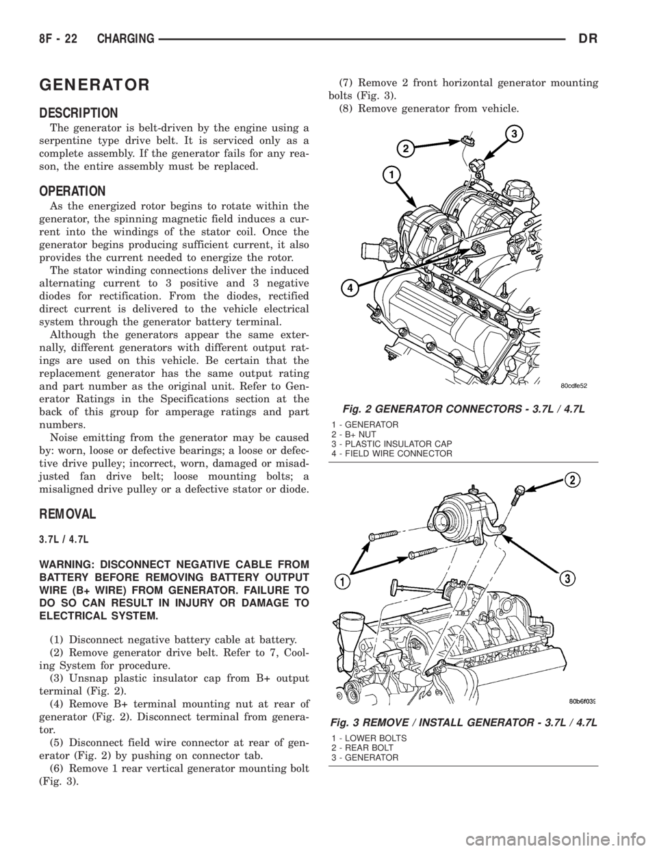
(3) Unsnap plastic insulator cap from B+ output
terminal (Fig. 2).
(4) Remove B+ terminal mounting nut at rear of
generator (Fig. 2). Disconnect terminal from genera-
tor.
(5) Disconnect field wire connector at rear of gen-
erator (Fig. 2) by pushing on connector tab.
(6) Remove 1 rear vertical generator mounting bolt
(Fig. 3).(7) Remove 2 front horizontal generator mounting
bolts (Fig. 3).
(8) Remove generator from vehicle.
Fig. 2 GENERATOR CONNECTORS - 3.7L / 4.7L
1 - GENERATOR
2-B+NUT
3 - PLASTIC INSULATOR CAP
4 - FIELD WIRE CONNECTOR
Fig. 3 REMOVE / INSTALL GENERATOR - 3.7L / 4.7L
1 - LOWER BOLTS
2 - REAR BOLT
3 - GENERATOR
8F - 22 CHARGINGDR
Page 484 of 2895

NOTE: Over or under tightening the sensor mount-
ing bolts will affect knock sensor performance, pos-
sibly causing improper spark control. Always use
the specified torque when installing the knock sen-
sors. The torque for the knock senor bolt is rela-
tively light for an 8mm bolt.
NOTE: Note foam strip on bolt threads. This foam is
used only to retain the bolts to sensors for plant
assembly. It is not used as a sealant. Do not apply
any adhesive, sealant or thread locking compound
to these bolts.
(3) Install and tighten mounting bolts. Refer to
torque specification.
(4) Install intake manifold. Refer to Engine sec-
tion.
(5) Connect knock sensor wiring harness to engine
harness at rear of intake manifold.
5.7L V-8
(1) Thoroughly clean knock sensor mounting hole.
(2) Install sensor into cylinder block.
NOTE: Over or under tightening the sensor mount-
ing bolts will affect knock sensor performance, pos-
sibly causing improper spark control. Always use
the specified torque when installing the knock sen-
sors. The torque for the knock senor bolt is rela-
tively light for an 8mm bolt.
NOTE: Note foam strip on bolt threads. This foam is
used only to retain the bolts to sensors for plant
assembly. It is not used as a sealant. Do not apply
any adhesive, sealant or thread locking compound
to these bolts.
(3) Install and tighten mounting bolt. Refer to
torque specification.
(4) Install electrical connector to sensor.
SPARK PLUG
DESCRIPTION
Resistor type spark plugs are used on all engines.
Sixteen spark plugs (2 per cylinder) are used with
5.7L V-8 engines.
DIAGNOSIS AND TESTING - SPARK PLUG
CONDITIONS
To prevent possible pre-ignition and/or mechanical
engine damage, the correct type/heat range/number
spark plug must be used.
Always use the recommended torque when tighten-
ing spark plugs. Incorrect torque can distort the
spark plug and change plug gap. It can also pull the
plug threads and do possible damage to both the
spark plug and the cylinder head.
Remove the spark plugs and examine them for
burned electrodes and fouled, cracked or broken por-
celain insulators. Keep plugs arranged in the order
in which they were removed from the engine. A sin-
gle plug displaying an abnormal condition indicates
that a problem exists in the corresponding cylinder.
Replace spark plugs at the intervals recommended in
the Lubrication and Maintenance section.
Spark plugs that have low mileage may be cleaned
and reused if not otherwise defective, carbon or oil
fouled.
CAUTION: Never use a motorized wire wheel brush
to clean the spark plugs. Metallic deposits will
remain on the spark plug insulator and will cause
plug misfire.
Spark plug resistance values range from 6,000 to
20,000 ohms (when checked with at least a 1000 volt
spark plug tester).Do not use an ohmmeter to
check the resistance values of the spark plugs.
Inaccurate readings will result.
NORMAL OPERATING
The few deposits present on the spark plug will
probably be light tan or slightly gray in color. This is
evident with most grades of commercial gasoline
(Fig. 42). There will not be evidence of electrode
burning. Gap growth will not average more than
approximately 0.025 mm (.001 in) per 3200 km (2000
miles) of operation. Spark plugs that have normal
wear can usually be cleaned, have the electrodes
filed, have the gap set and then be installed.
Some fuel refiners in several areas of the United
States have introduced a manganese additive (MMT)
for unleaded fuel. During combustion, fuel with MMT
causes the entire tip of the spark plug to be coated
with a rust colored deposit. This rust color can be
misdiagnosed as being caused by coolant in the com-
bustion chamber. Spark plug performance may be
affected by MMT deposits.
DRIGNITION CONTROL 8I - 27
KNOCK SENSOR (Continued)