2003 DODGE RAM dimensions
[x] Cancel search: dimensionsPage 1248 of 2895
DIAGNOSIS & TESTING - RELAY CIRCUIT TEST
(1) The relay common feed terminal cavity (30) of
the integrated power module is connected to battery
voltage and should be hot at all times. Check for bat-
tery voltage at the fused B(+) circuit cavity in the
integrated power module receptacle for the relay. If
OK, go to Step 2. If not OK, repair the fused B(+) cir-
cuit to the integrated power module fuse as required.
(2) The relay normally closed terminal (87A) is
connected to terminal 30 in the de-energized position,
but is not used for this application. Go to Step 3.
(3) The relay normally open terminal (87) is con-
nected to the common feed terminal (30) in the ener-
gized position. This terminal supplies battery voltage
to the fused B(+) fuse in the integrated power module
that feeds the accessory when the relay is energized
by the ignition switch. There should be continuity
between the integrated power module cavity for relay
terminal 87 and the fused B(+) fuse in the integrated
power module at all times. If OK, go to Step 4. If not
OK, repair the open fused B(+) circuit to the inte-
grated power module fuse as required.
(4) The coil ground terminal (85) is connected to
the electromagnet in the relay. It receives battery
feed to energize the relay when the ignition switch is
in the Accessory or Run positions. Turn the ignition
switch to the On position. Check for battery voltage
at the fused ignition switch output (acc/run) circuit
cavity for relay terminal 85 in the integrated power
module receptacle for the relay. If OK, go to Step 5. If
not OK, repair the open fused ignition switch output
(acc/run) circuit to the ignition switch as required.
(5) The coil battery terminal (86) is connected to
the electromagnet in the relay. The integrated power
module cavity for this terminal should have continu-
ity to ground at all times. If not OK, repair the open
ground circuit to ground as required.
REMOVAL
(1) Disconnect and isolate the negative battery
cable.
(2) Remove the relay by grasping it firmly and
pulling it straight out from its receptacle. A slight
back and fourth rocking motion may help the
removal process.
INSTALLATION
(1) Position the relay to the proper receptacle.
(2) Align the relay terminals with the terminal
cavities in the receptacle.
(3) Push firmly and evenly on the top of the relay
until the terminals are fully seated in the terminal
cavities in the receptacle.
(4) Connect the negative battery cable.
MICRO RELAY
DESCRIPTION
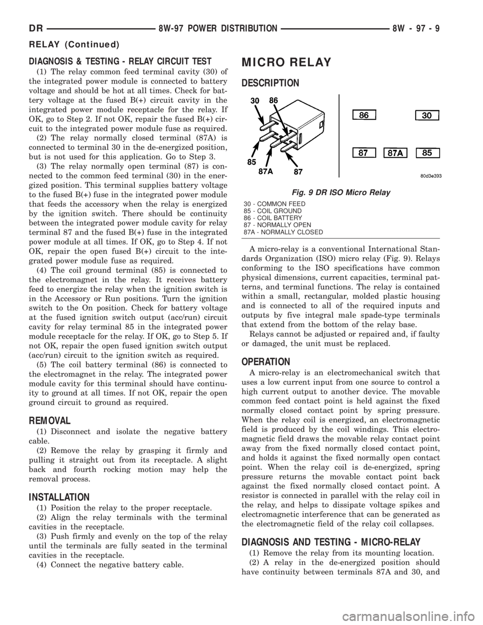
A micro-relay is a conventional International Stan-
dards Organization (ISO) micro relay (Fig. 9). Relays
conforming to the ISO specifications have common
physical dimensions, current capacities, terminal pat-
terns, and terminal functions. The relay is contained
within a small, rectangular, molded plastic housing
and is connected to all of the required inputs and
outputs by five integral male spade-type terminals
that extend from the bottom of the relay base.
Relays cannot be adjusted or repaired and, if faulty
or damaged, the unit must be replaced.
OPERATION
A micro-relay is an electromechanical switch that
uses a low current input from one source to control a
high current output to another device. The movable
common feed contact point is held against the fixed
normally closed contact point by spring pressure.
When the relay coil is energized, an electromagnetic
field is produced by the coil windings. This electro-
magnetic field draws the movable relay contact point
away from the fixed normally closed contact point,
and holds it against the fixed normally open contact
point. When the relay coil is de-energized, spring
pressure returns the movable contact point back
against the fixed normally closed contact point. A
resistor is connected in parallel with the relay coil in
the relay, and helps to dissipate voltage spikes and
electromagnetic interference that can be generated as
the electromagnetic field of the relay coil collapses.
DIAGNOSIS AND TESTING - MICRO-RELAY
(1) Remove the relay from its mounting location.
(2) A relay in the de-energized position should
have continuity between terminals 87A and 30, and
Fig. 9 DR ISO Micro Relay
30 - COMMON FEED
85 - COIL GROUND
86 - COIL BATTERY
87 - NORMALLY OPEN
87A - NORMALLY CLOSED
DR8W-97 POWER DISTRIBUTION 8W - 97 - 9
RELAY (Continued)
Page 1561 of 2895
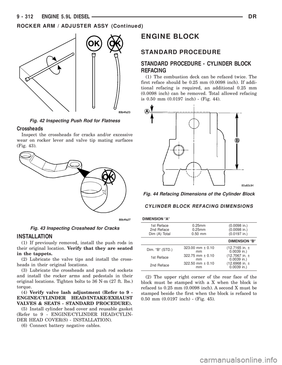
Crossheads
Inspect the crossheads for cracks and/or excessive
wear on rocker lever and valve tip mating surfaces
(Fig. 43).
INSTALLATION
(1) If previously removed, install the push rods in
their original location.Verify that they are seated
in the tappets.
(2) Lubricate the valve tips and install the cross-
heads in their original locations.
(3) Lubricate the crossheads and push rod sockets
and install the rocker arms and pedestals in their
original locations. Tighten bolts to 36 N´m (27 ft. lbs.)
torque.
(4)Verify valve lash adjustment (Refer to 9 -
ENGINE/CYLINDER HEAD/INTAKE/EXHAUST
VALVES & SEATS - STANDARD PROCEDURE).
(5) Install cylinder head cover and reusable gasket
(Refer to 9 - ENGINE/CYLINDER HEAD/CYLIN-
DER HEAD COVER(S) - INSTALLATION).
(6) Connect battery negative cables.
ENGINE BLOCK
STANDARD PROCEDURE
STANDARD PROCEDURE - CYLINDER BLOCK
REFACING
(1) The combustion deck can be refaced twice. The
first reface should be 0.25 mm (0.0098 inch). If addi-
tional refacing is required, an additional 0.25 mm
(0.0098 inch) can be removed. Total allowed refacing
is 0.50 mm (0.0197 inch) - (Fig. 44).
(2) The upper right corner of the rear face of the
block must be stamped with a X when the block is
refaced to 0.25 mm (0.0098 inch). A second X must be
stamped beside the first when the block is refaced to
0.50 mm (0.0197 inch) - (Fig. 45).
Fig. 42 Inspecting Push Rod for Flatness
Fig. 43 Inspecting Crosshead for Cracks
Fig. 44 Refacing Dimensions of the Cylinder Block
CYLINDER BLOCK REFACING DIMENSIONS
DIMENSION(A(
1st Reface 0.25mm (0.0098 in.)
2nd Reface 0.25mm (0.0098 in.)
Dim (A) Total 0.50 mm (0.0197 in.)
DIMENSION(B(
Dim.9B9(STD.)323.00 mm 0.10
mm(12.7165 in.
0.0039 in.)
1st Reface322.75 mm 0.10
mm(12.7067 in.
0.0039 in.)
2nd Reface322.50 mm 0.10
mm(12.6968 in.
0.0039 in.)
9 - 312 ENGINE 5.9L DIESELDR
ROCKER ARM / ADJUSTER ASSY (Continued)
Page 1562 of 2895
(3) Consult the parts catalog for the proper head
gaskets which must be used with refaced blocks to
ensure proper piston-to-valve clearance.
STANDARD PROCEDURE - CYLINDER BORE -
DE-GLAZE
(1) New piston rings may not seat in glazed cylin-
der bores.
(2) De-glazing gives the bore the correct surface
finish required to seat the rings. The size of the bore
is not changed by proper de-glazing.
(3) Cover the lube and tappet holes in the top of
the block with waterproof tape.
(4) It crankshaft is installed, wrap connecting rod
journals with clean cloth. Cover cloth with water-
proof tape.
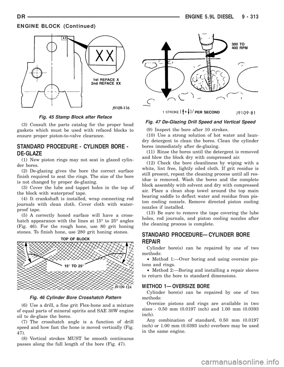
(5) A correctly honed surface will have a cross-
hatch appearance with the lines at 15É to 25É angles
(Fig. 46). For the rough hone, use 80 grit honing
stones. To finish hone, use 280 grit honing stones.
(6) Use a drill, a fine grit Flex-hone and a mixture
of equal parts of mineral spirits and SAE 30W engine
oil to de-glaze the bores.
(7) The crosshatch angle is a function of drill
speed and how fast the hone is moved vertically (Fig.
47).
(8) Vertical strokes MUST be smooth continuous
passes along the full length of the bore (Fig. 47).(9) Inspect the bore after 10 strokes.
(10) Use a strong solution of hot water and laun-
dry detergent to clean the bores. Clean the cylinder
bores immediately after de-glazing.
(11) Rinse the bores until the detergent is removed
and blow the block dry with compressed air.
(12) Check the bore cleanliness by wiping with a
white, lint free, lightly oiled cloth. If grit residue is
still present, repeat the cleaning process until all res-
idue is removed. Wash the bores and the complete
block assembly with solvent and dry with compressed
air. Place a clean shop towel around the top main
bearing saddle to deflect water and residue from pis-
ton cooling nozzels. Remove directed piston cooling
nozzles if installed.
(13) Be sure to remove the tape covering the lube
holes, rod journals, and piston cooling nozzles after
the cleaning process is complete.
STANDARD PROCEDUREÐCYLINDER BORE
REPAIR
Cylinder bore(s) can be repaired by one of two
methods:
²Method 1:ÐOver boring and using oversize pis-
tons and rings.
²Method 2:ÐBoring and installing a repair sleeve
to return the bore to standard dimensions.
METHOD 1ÐOVERSIZE BORE
Cylinder bore(s) can be repaired by one of two
methods:
Oversize pistons and rings are available in two
sizes - 0.50 mm (0.0197 inch) and 1.00 mm (0.0393
inch).
Any combination of standard, 0.50 mm (0.0197
inch) or 1.00 mm (0.0393 inch) overbore may be used
in the same engine.
Fig. 45 Stamp Block after Reface
Fig. 46 Cylinder Bore Crosshatch Pattern
Fig. 47 De-Glazing Drill Speed and Vertical Speed
DRENGINE 5.9L DIESEL 9 - 313
ENGINE BLOCK (Continued)
Page 1563 of 2895
If more than 1.00 mm (0.0393 inch) overbore is
needed, a repair sleeve can be installed (refer to
Method 2ÐRepair Sleeve).
Cylinder block bores may be bored twice before use
of a repair sleeve is required. The first bore is 0.50
mm (0.0197 inch) oversize. The second bore is 1.00
mm (0.0393 inch) oversize.
After boring to size, use a honing stone to chamfer
the edge of the bore.
CYLINDER BORE DIMENSION CHART
DESCRIPTION MEASUREMENT
BORING DIAMETER
DIMENSION1st. REBORE - 102.469
mm (4.0342 in.)
2nd. REBORE - 102.969
mm (4.0539 in.)
HONING DIAMETER
DIMENSIONSSTANDARD - 102.020
0.020 mm (4.0165
0.0008 in.)
1st. REBORE - 102.520
0.020 mm (4.0362
0.0008 in.)
2nd. REBORE - 103.020
0.020 mm 4.0559
0.0008 in.)
CHAMFER
DIMENSIONSApprox. 1.25 mm (0.049
in.) by 15É
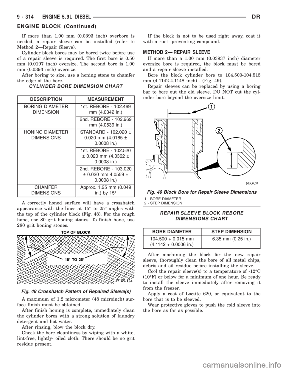
A correctly honed surface will have a crosshatch
appearance with the lines at 15É to 25É angles with
the top of the cylinder block (Fig. 48). For the rough
hone, use 80 grit honing stones. To finish hone, use
280 grit honing stones.
A maximum of 1.2 micrometer (48 microinch) sur-
face finish must be obtained.
After finish honing is complete, immediately clean
the cylinder bores with a strong solution of laundry
detergent and hot water.
After rinsing, blow the block dry.
Check the bore cleanliness by wiping with a white,
lint-free, lightly- oiled cloth. There should be no grit
residue present.If the block is not to be used right away, coat it
with a rust- preventing compound.
METHOD 2ÐREPAIR SLEEVE
If more than a 1.00 mm (0.03937 inch) diameter
oversize bore is required, the block must be bored
and a repair sleeve installed.
Bore the block cylinder bore to 104.500-104.515
mm (4.1142-4.1148 inch) - (Fig. 49).
Repair sleeves can be replaced by using a boring
bar to bore out the old sleeve. DO NOT cut the cyl-
inder bore beyond the oversize limit.
REPAIR SLEEVE BLOCK REBORE
DIMENSIONS CHART
BORE DIAMETER STEP DIMENSION
104.500 + 0.015 mm
(4.1142 + 0.0006 in.)6.35 mm (0.25 in.)
After machining the block for the new repair
sleeve, thoroughly clean the bore of all metal chips,
debris and oil residue before installing the sleeve.
Cool the repair sleeve(s) to a temperature of -12ÉC
(10ÉF) or below for a minimum of one hour. Be ready
to install the sleeve immediately after removing it
from the freezer.
Apply a coat of Loctite 620, or equivalent to the
bore that is to be sleeved.
Wear protective gloves to push the cold sleeve into
the bore as far as possible.
Fig. 48 Crosshatch Pattern of Repaired Sleeve(s)
Fig. 49 Block Bore for Repair Sleeve Dimensions
1 - BORE DIAMETER
2 - STEP DIMENSION
9 - 314 ENGINE 5.9L DIESELDR
ENGINE BLOCK (Continued)
Page 1564 of 2895
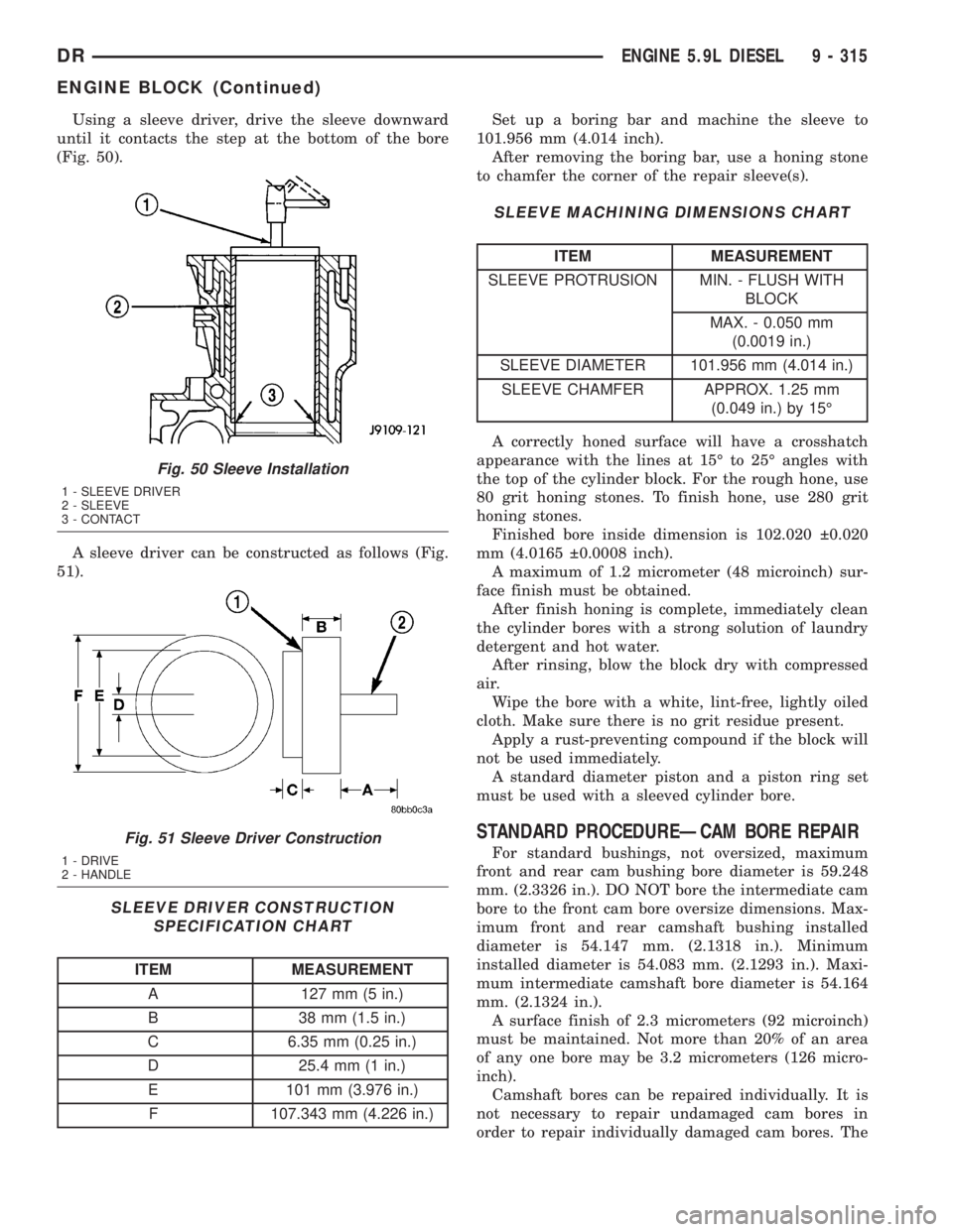
Using a sleeve driver, drive the sleeve downward
until it contacts the step at the bottom of the bore
(Fig. 50).
A sleeve driver can be constructed as follows (Fig.
51).
SLEEVE DRIVER CONSTRUCTION
SPECIFICATION CHART
ITEM MEASUREMENT
A 127 mm (5 in.)
B 38 mm (1.5 in.)
C 6.35 mm (0.25 in.)
D 25.4 mm (1 in.)
E 101 mm (3.976 in.)
F 107.343 mm (4.226 in.)Set up a boring bar and machine the sleeve to
101.956 mm (4.014 inch).
After removing the boring bar, use a honing stone
to chamfer the corner of the repair sleeve(s).
SLEEVE MACHINING DIMENSIONS CHART
ITEM MEASUREMENT
SLEEVE PROTRUSION MIN. - FLUSH WITH
BLOCK
MAX. - 0.050 mm
(0.0019 in.)
SLEEVE DIAMETER 101.956 mm (4.014 in.)
SLEEVE CHAMFER APPROX. 1.25 mm
(0.049 in.) by 15É
A correctly honed surface will have a crosshatch
appearance with the lines at 15É to 25É angles with
the top of the cylinder block. For the rough hone, use
80 grit honing stones. To finish hone, use 280 grit
honing stones.
Finished bore inside dimension is 102.020 0.020
mm (4.0165 0.0008 inch).
A maximum of 1.2 micrometer (48 microinch) sur-
face finish must be obtained.
After finish honing is complete, immediately clean
the cylinder bores with a strong solution of laundry
detergent and hot water.
After rinsing, blow the block dry with compressed
air.
Wipe the bore with a white, lint-free, lightly oiled
cloth. Make sure there is no grit residue present.
Apply a rust-preventing compound if the block will
not be used immediately.
A standard diameter piston and a piston ring set
must be used with a sleeved cylinder bore.
STANDARD PROCEDUREÐCAM BORE REPAIR
For standard bushings, not oversized, maximum
front and rear cam bushing bore diameter is 59.248
mm. (2.3326 in.). DO NOT bore the intermediate cam
bore to the front cam bore oversize dimensions. Max-
imum front and rear camshaft bushing installed
diameter is 54.147 mm. (2.1318 in.). Minimum
installed diameter is 54.083 mm. (2.1293 in.). Maxi-
mum intermediate camshaft bore diameter is 54.164
mm. (2.1324 in.).
A surface finish of 2.3 micrometers (92 microinch)
must be maintained. Not more than 20% of an area
of any one bore may be 3.2 micrometers (126 micro-
inch).
Camshaft bores can be repaired individually. It is
not necessary to repair undamaged cam bores in
order to repair individually damaged cam bores. The
Fig. 50 Sleeve Installation
1 - SLEEVE DRIVER
2 - SLEEVE
3 - CONTACT
Fig. 51 Sleeve Driver Construction
1 - DRIVE
2 - HANDLE
DRENGINE 5.9L DIESEL 9 - 315
ENGINE BLOCK (Continued)
Page 1567 of 2895
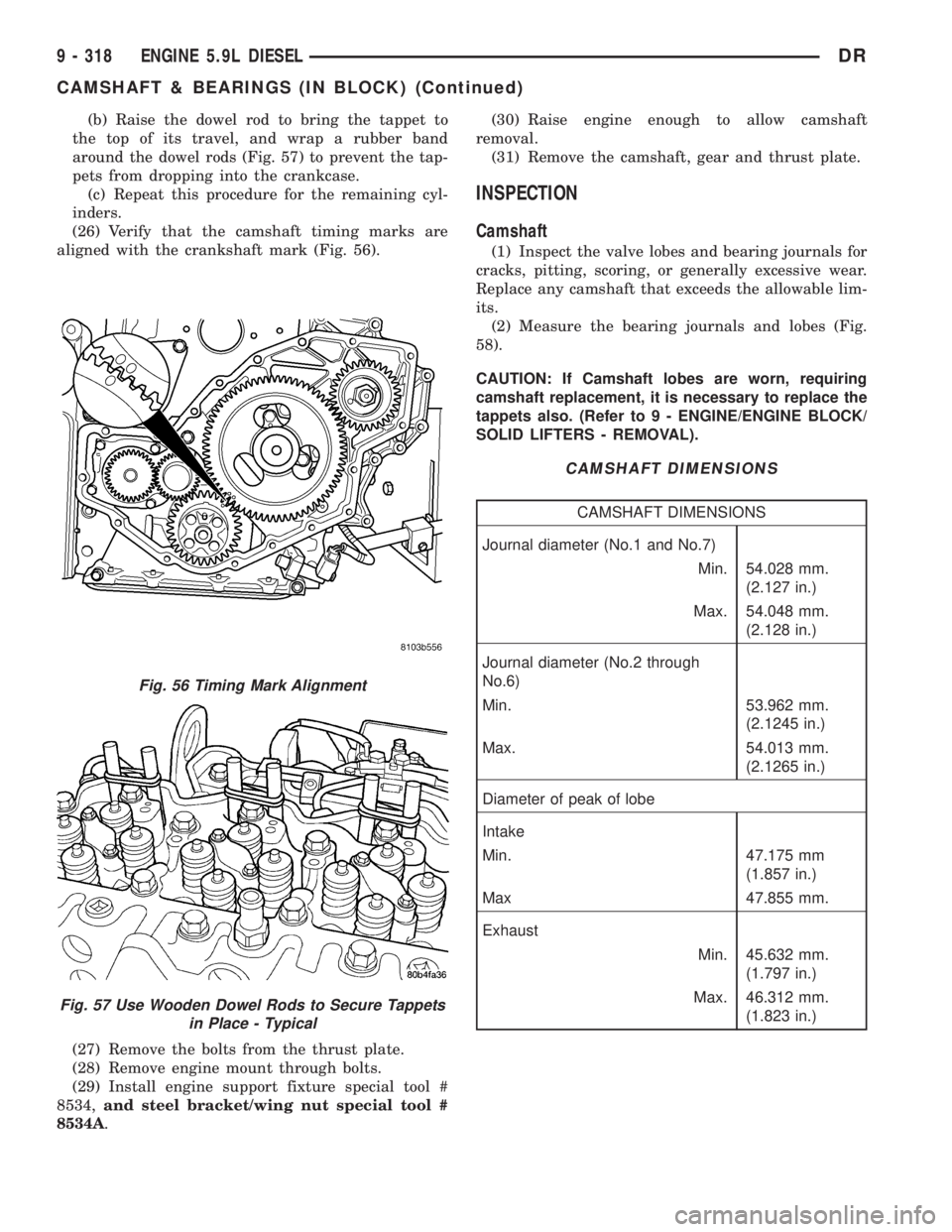
(b) Raise the dowel rod to bring the tappet to
the top of its travel, and wrap a rubber band
around the dowel rods (Fig. 57) to prevent the tap-
pets from dropping into the crankcase.
(c) Repeat this procedure for the remaining cyl-
inders.
(26) Verify that the camshaft timing marks are
aligned with the crankshaft mark (Fig. 56).
(27) Remove the bolts from the thrust plate.
(28) Remove engine mount through bolts.
(29) Install engine support fixture special tool #
8534,and steel bracket/wing nut special tool #
8534A.(30) Raise engine enough to allow camshaft
removal.
(31) Remove the camshaft, gear and thrust plate.
INSPECTION
Camshaft
(1) Inspect the valve lobes and bearing journals for
cracks, pitting, scoring, or generally excessive wear.
Replace any camshaft that exceeds the allowable lim-
its.
(2) Measure the bearing journals and lobes (Fig.
58).
CAUTION: If Camshaft lobes are worn, requiring
camshaft replacement, it is necessary to replace the
tappets also. (Refer to 9 - ENGINE/ENGINE BLOCK/
SOLID LIFTERS - REMOVAL).
CAMSHAFT DIMENSIONS
CAMSHAFT DIMENSIONS
Journal diameter (No.1 and No.7)
Min. 54.028 mm.
(2.127 in.)
Max. 54.048 mm.
(2.128 in.)
Journal diameter (No.2 through
No.6)
Min. 53.962 mm.
(2.1245 in.)
Max. 54.013 mm.
(2.1265 in.)
Diameter of peak of lobe
Intake
Min. 47.175 mm
(1.857 in.)
Max 47.855 mm.
Exhaust
Min. 45.632 mm.
(1.797 in.)
Max. 46.312 mm.
(1.823 in.)
Fig. 56 Timing Mark Alignment
Fig. 57 Use Wooden Dowel Rods to Secure Tappets
in Place - Typical
9 - 318 ENGINE 5.9L DIESELDR
CAMSHAFT & BEARINGS (IN BLOCK) (Continued)
Page 1672 of 2895
FRAMES & BUMPERS
TABLE OF CONTENTS
page page
BUMPERS
SPECIFICATIONS - TORQUE...............1
FRONT AIR DAM
REMOVAL.............................2
INSTALLATION..........................2
FRONT BUMPER
REMOVAL.............................2
INSTALLATION..........................2
FRONT FASCIA
REMOVAL.............................3
INSTALLATION..........................3
REAR BUMPER
REMOVAL.............................4
INSTALLATION..........................4
FRAME
STANDARD PROCEDURE
STANDARD PROCEDURE - LIGHT DUTY
FRONT FRAME RAIL TIP REPLACEMENT....4
STANDARD PROCEDURE - HYDROFORM
FENDER RAIL REPAIR.................12
STANDARD PROCEDURE - REAR FRAME
H-SECTION REPLACEMENT.............15SPECIFICATIONS
SPECIFICATIONS - FRAME DIMENSIONS . . . 17
SPECIFICATIONS - TORQUE............23
FRONT CROSSMEMBER
REMOVAL.............................23
INSTALLATION.........................23
FRONT SKID PLATE
REMOVAL.............................24
INSTALLATION.........................24
TRANSMISSION CROSSMEMBER
REMOVAL.............................24
INSTALLATION.........................25
TRAILER HITCH
REMOVAL.............................25
INSTALLATION.........................25
TRANSFER CASE SKID PLATE
REMOVAL.............................26
INSTALLATION.........................26
FRONT TOW HOOK ASSEMBLY
REMOVAL.............................26
INSTALLATION.........................26
BUMPERS
SPECIFICATIONS - TORQUE
TORQUE SPECIFICATIONS
DESCRIPTION N´m Ft. Lbs. In. Lbs.
Front bumper center bracket nuts 95 70 Ð
Front bumper stud plate nuts 95 70 Ð
License plate hitch reinforcement bolts 54 40 Ð
Rear bumper support bracket stud plate nuts 54 40 Ð
Rear bumper support bracket to hitch bolts 54 40 Ð
Rear bumper to hitch bolts 54 40 Ð
DRFRAMES & BUMPERS 13 - 1
Page 1677 of 2895
(11) Assemble the service sleeve. Refer to SER-
VICE SLEEVE ASSEMBLY at the end of this proce-
dure.
NOTE: Any burned surface coatings will need to be
removed from the sleeve prior to installation and
application of corrosion preventative coatings.
(12) Smooth and square the cut edges of the origi-
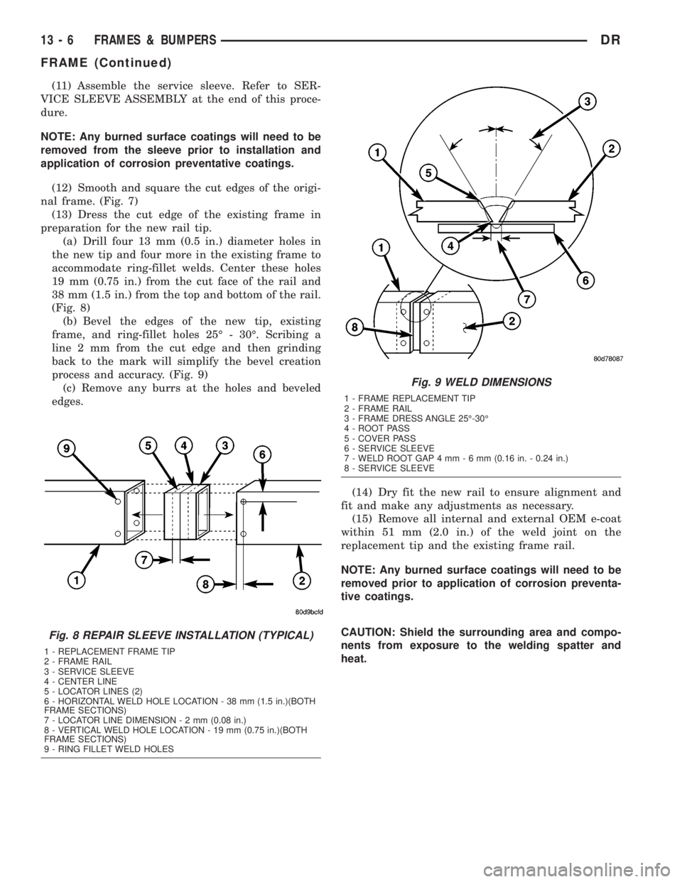
nal frame. (Fig. 7)
(13) Dress the cut edge of the existing frame in
preparation for the new rail tip.
(a) Drill four 13 mm (0.5 in.) diameter holes in
the new tip and four more in the existing frame to
accommodate ring-fillet welds. Center these holes
19 mm (0.75 in.) from the cut face of the rail and
38 mm (1.5 in.) from the top and bottom of the rail.
(Fig. 8)
(b) Bevel the edges of the new tip, existing
frame, and ring-fillet holes 25É - 30É. Scribing a
line 2 mm from the cut edge and then grinding
back to the mark will simplify the bevel creation
process and accuracy. (Fig. 9)
(c) Remove any burrs at the holes and beveled
edges.
(14) Dry fit the new rail to ensure alignment and
fit and make any adjustments as necessary.
(15) Remove all internal and external OEM e-coat
within 51 mm (2.0 in.) of the weld joint on the
replacement tip and the existing frame rail.
NOTE: Any burned surface coatings will need to be
removed prior to application of corrosion preventa-
tive coatings.
CAUTION: Shield the surrounding area and compo-
nents from exposure to the welding spatter and
heat.
Fig. 8 REPAIR SLEEVE INSTALLATION (TYPICAL)
1 - REPLACEMENT FRAME TIP
2 - FRAME RAIL
3 - SERVICE SLEEVE
4 - CENTER LINE
5 - LOCATOR LINES (2)
6 - HORIZONTAL WELD HOLE LOCATION - 38 mm (1.5 in.)(BOTH
FRAME SECTIONS)
7 - LOCATOR LINE DIMENSION-2mm(0.08 in.)
8 - VERTICAL WELD HOLE LOCATION - 19 mm (0.75 in.)(BOTH
FRAME SECTIONS)
9 - RING FILLET WELD HOLES
Fig. 9 WELD DIMENSIONS
1 - FRAME REPLACEMENT TIP
2 - FRAME RAIL
3 - FRAME DRESS ANGLE 25É-30É
4 - ROOT PASS
5 - COVER PASS
6 - SERVICE SLEEVE
7 - WELD ROOT GAP 4 mm-6mm(0.16 in. - 0.24 in.)
8 - SERVICE SLEEVE
13 - 6 FRAMES & BUMPERSDR
FRAME (Continued)