2003 DODGE RAM dimensions
[x] Cancel search: dimensionsPage 1680 of 2895
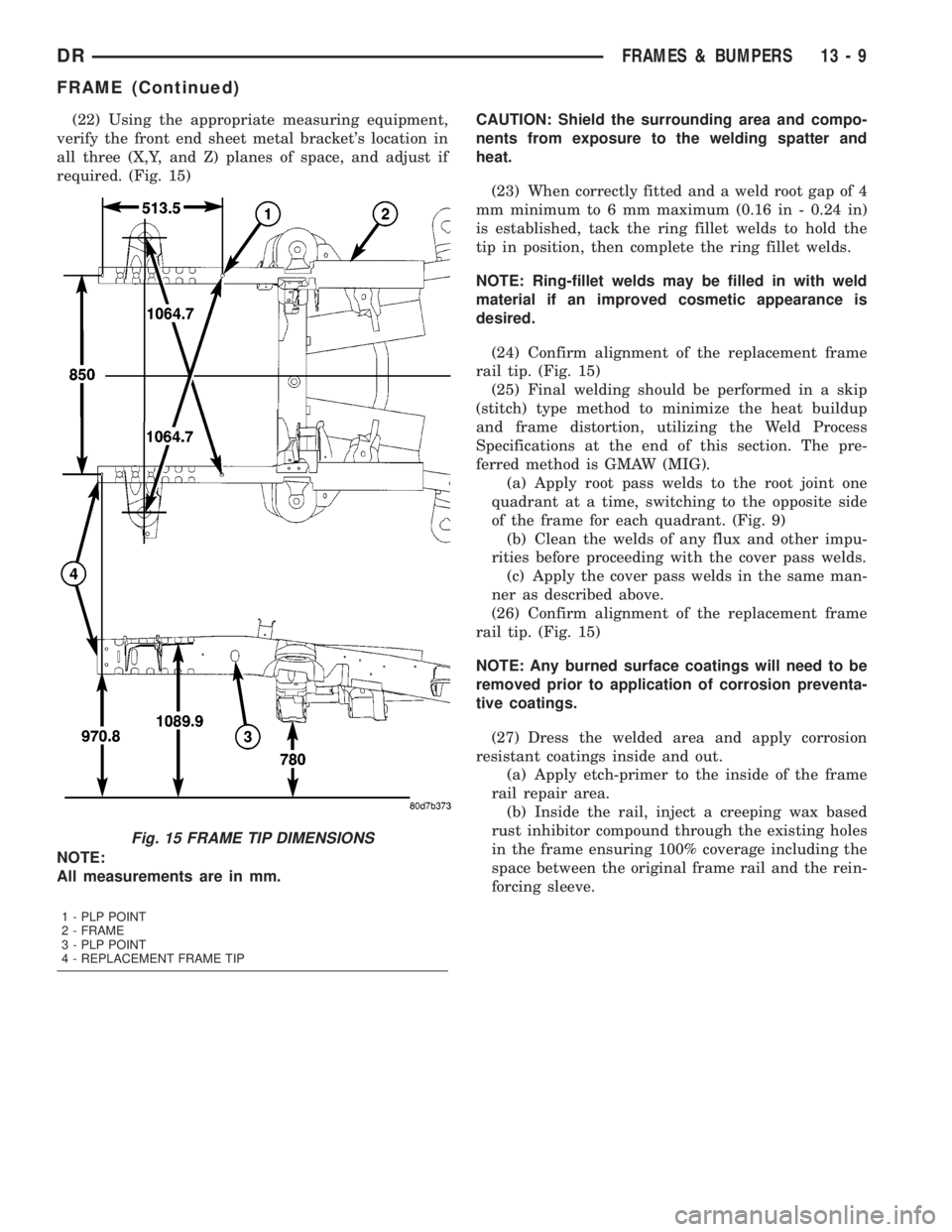
(22) Using the appropriate measuring equipment,
verify the front end sheet metal bracket's location in
all three (X,Y, and Z) planes of space, and adjust if
required. (Fig. 15)CAUTION: Shield the surrounding area and compo-
nents from exposure to the welding spatter and
heat.
(23) When correctly fitted and a weld root gap of 4
mm minimum to 6 mm maximum (0.16 in - 0.24 in)
is established, tack the ring fillet welds to hold the
tip in position, then complete the ring fillet welds.
NOTE: Ring-fillet welds may be filled in with weld
material if an improved cosmetic appearance is
desired.
(24) Confirm alignment of the replacement frame
rail tip. (Fig. 15)
(25) Final welding should be performed in a skip
(stitch) type method to minimize the heat buildup
and frame distortion, utilizing the Weld Process
Specifications at the end of this section. The pre-
ferred method is GMAW (MIG).
(a) Apply root pass welds to the root joint one
quadrant at a time, switching to the opposite side
of the frame for each quadrant. (Fig. 9)
(b) Clean the welds of any flux and other impu-
rities before proceeding with the cover pass welds.
(c) Apply the cover pass welds in the same man-
ner as described above.
(26) Confirm alignment of the replacement frame
rail tip. (Fig. 15)
NOTE: Any burned surface coatings will need to be
removed prior to application of corrosion preventa-
tive coatings.
(27) Dress the welded area and apply corrosion
resistant coatings inside and out.
(a) Apply etch-primer to the inside of the frame
rail repair area.
(b) Inside the rail, inject a creeping wax based
rust inhibitor compound through the existing holes
in the frame ensuring 100% coverage including the
space between the original frame rail and the rein-
forcing sleeve.
Fig. 15 FRAME TIP DIMENSIONS
NOTE:
All measurements are in mm.
1 - PLP POINT
2 - FRAME
3 - PLP POINT
4 - REPLACEMENT FRAME TIP
DRFRAMES & BUMPERS 13 - 9
FRAME (Continued)
Page 1687 of 2895
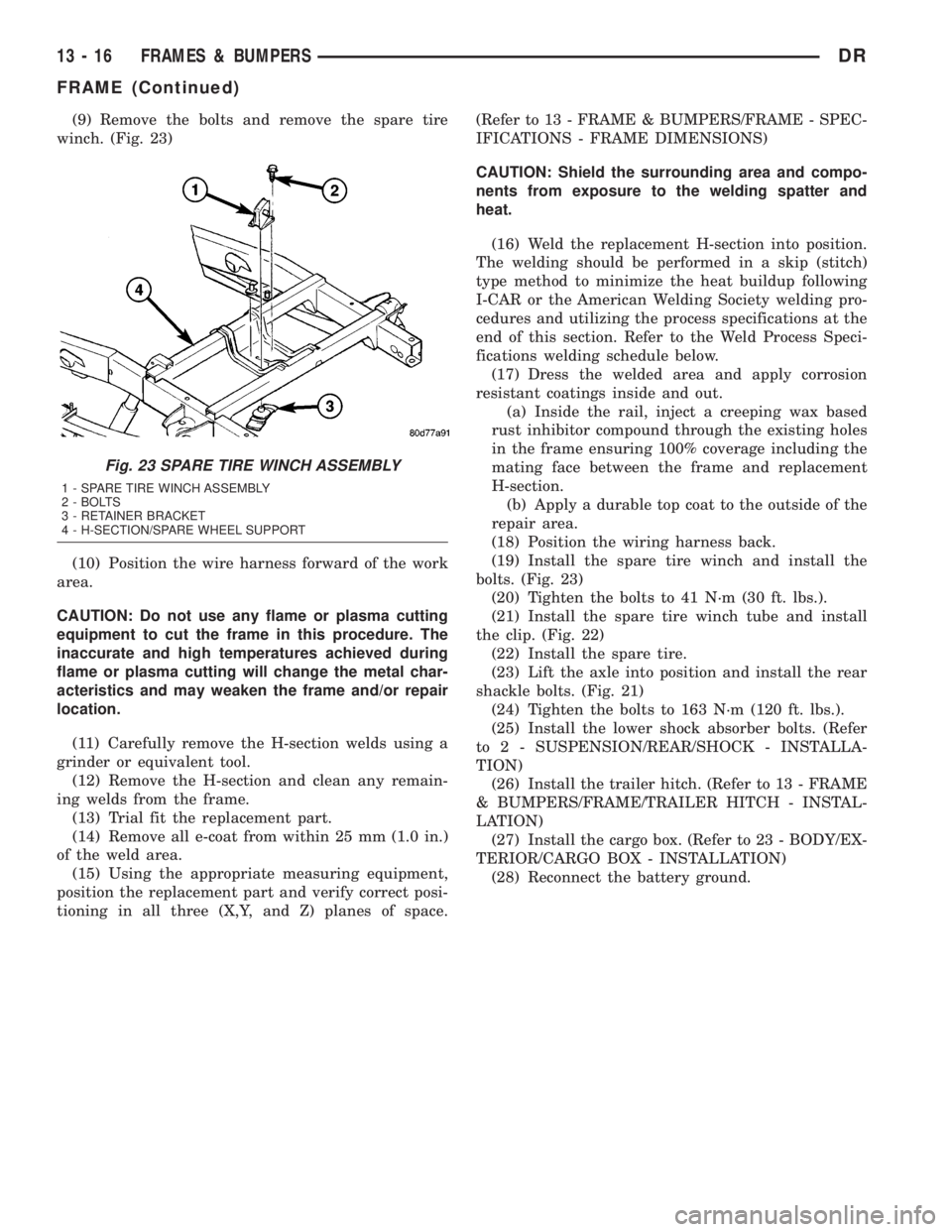
(9) Remove the bolts and remove the spare tire
winch. (Fig. 23)
(10) Position the wire harness forward of the work
area.
CAUTION: Do not use any flame or plasma cutting
equipment to cut the frame in this procedure. The
inaccurate and high temperatures achieved during
flame or plasma cutting will change the metal char-
acteristics and may weaken the frame and/or repair
location.
(11) Carefully remove the H-section welds using a
grinder or equivalent tool.
(12) Remove the H-section and clean any remain-
ing welds from the frame.
(13) Trial fit the replacement part.
(14) Remove all e-coat from within 25 mm (1.0 in.)
of the weld area.
(15) Using the appropriate measuring equipment,
position the replacement part and verify correct posi-
tioning in all three (X,Y, and Z) planes of space.(Refer to 13 - FRAME & BUMPERS/FRAME - SPEC-
IFICATIONS - FRAME DIMENSIONS)
CAUTION: Shield the surrounding area and compo-
nents from exposure to the welding spatter and
heat.
(16) Weld the replacement H-section into position.
The welding should be performed in a skip (stitch)
type method to minimize the heat buildup following
I-CAR or the American Welding Society welding pro-
cedures and utilizing the process specifications at the
end of this section. Refer to the Weld Process Speci-
fications welding schedule below.
(17) Dress the welded area and apply corrosion
resistant coatings inside and out.
(a) Inside the rail, inject a creeping wax based
rust inhibitor compound through the existing holes
in the frame ensuring 100% coverage including the
mating face between the frame and replacement
H-section.
(b) Apply a durable top coat to the outside of the
repair area.
(18) Position the wiring harness back.
(19) Install the spare tire winch and install the
bolts. (Fig. 23)
(20) Tighten the bolts to 41 N´m (30 ft. lbs.).
(21) Install the spare tire winch tube and install
the clip. (Fig. 22)
(22) Install the spare tire.
(23) Lift the axle into position and install the rear
shackle bolts. (Fig. 21)
(24) Tighten the bolts to 163 N´m (120 ft. lbs.).
(25) Install the lower shock absorber bolts. (Refer
to 2 - SUSPENSION/REAR/SHOCK - INSTALLA-
TION)
(26) Install the trailer hitch. (Refer to 13 - FRAME
& BUMPERS/FRAME/TRAILER HITCH - INSTAL-
LATION)
(27) Install the cargo box. (Refer to 23 - BODY/EX-
TERIOR/CARGO BOX - INSTALLATION)
(28) Reconnect the battery ground.
Fig. 23 SPARE TIRE WINCH ASSEMBLY
1 - SPARE TIRE WINCH ASSEMBLY
2 - BOLTS
3 - RETAINER BRACKET
4 - H-SECTION/SPARE WHEEL SUPPORT
13 - 16 FRAMES & BUMPERSDR
FRAME (Continued)
Page 1688 of 2895
CAUTION:
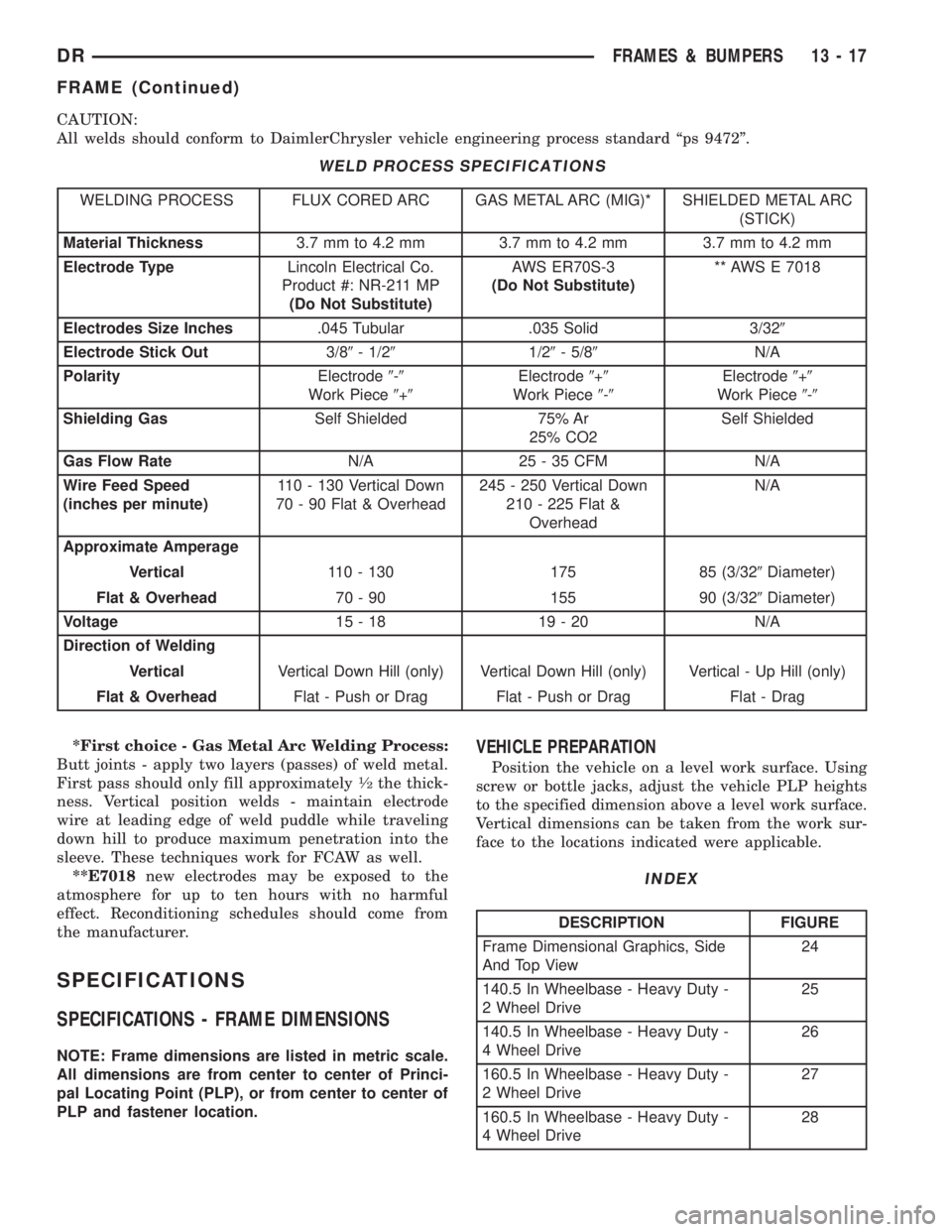
All welds should conform to DaimlerChrysler vehicle engineering process standard ªps 9472º.
WELD PROCESS SPECIFICATIONS
WELDING PROCESS FLUX CORED ARC GAS METAL ARC (MIG)* SHIELDED METAL ARC
(STICK)
Material Thickness3.7 mm to 4.2 mm 3.7 mm to 4.2 mm 3.7 mm to 4.2 mm
Electrode TypeLincoln Electrical Co.
Product #: NR-211 MP
(Do Not Substitute)AWS ER70S-3
(Do Not Substitute)** AWS E 7018
Electrodes Size Inches.045 Tubular .035 Solid 3/329
Electrode Stick Out3/89- 1/291/29- 5/89N/A
PolarityElectrode9-9
Work Piece9+9Electrode9+9
Work Piece9-9Electrode9+9
Work Piece9-9
Shielding GasSelf Shielded 75% Ar
25% CO2Self Shielded
Gas Flow RateN/A 25 - 35 CFM N/A
Wire Feed Speed
(inches per minute)110 - 130 Vertical Down
70 - 90 Flat & Overhead245 - 250 Vertical Down
210 - 225 Flat &
OverheadN/A
Approximate Amperage
Vertical110 - 130 175 85 (3/329Diameter)
Flat & Overhead70 - 90 155 90 (3/329Diameter)
Voltage15-18 19-20 N/A
Direction of Welding
VerticalVertical Down Hill (only) Vertical Down Hill (only) Vertical - Up Hill (only)
Flat & OverheadFlat - Push or Drag Flat - Push or Drag Flat - Drag
*First choice - Gas Metal Arc Welding Process:
Butt joints - apply two layers (passes) of weld metal.
First pass should only fill approximately
1¤2the thick-
ness. Vertical position welds - maintain electrode
wire at leading edge of weld puddle while traveling
down hill to produce maximum penetration into the
sleeve. These techniques work for FCAW as well.
**E7018new electrodes may be exposed to the
atmosphere for up to ten hours with no harmful
effect. Reconditioning schedules should come from
the manufacturer.
SPECIFICATIONS
SPECIFICATIONS - FRAME DIMENSIONS
NOTE: Frame dimensions are listed in metric scale.
All dimensions are from center to center of Princi-
pal Locating Point (PLP), or from center to center of
PLP and fastener location.
VEHICLE PREPARATION
Position the vehicle on a level work surface. Using
screw or bottle jacks, adjust the vehicle PLP heights
to the specified dimension above a level work surface.
Vertical dimensions can be taken from the work sur-
face to the locations indicated were applicable.
INDEX
DESCRIPTION FIGURE
Frame Dimensional Graphics, Side
And Top View24
140.5 In Wheelbase - Heavy Duty -
2 Wheel Drive25
140.5 In Wheelbase - Heavy Duty -
4 Wheel Drive26
160.5 In Wheelbase - Heavy Duty -
2 Wheel Drive27
160.5 In Wheelbase - Heavy Duty -
4 Wheel Drive28
DRFRAMES & BUMPERS 13 - 17
FRAME (Continued)
Page 1689 of 2895
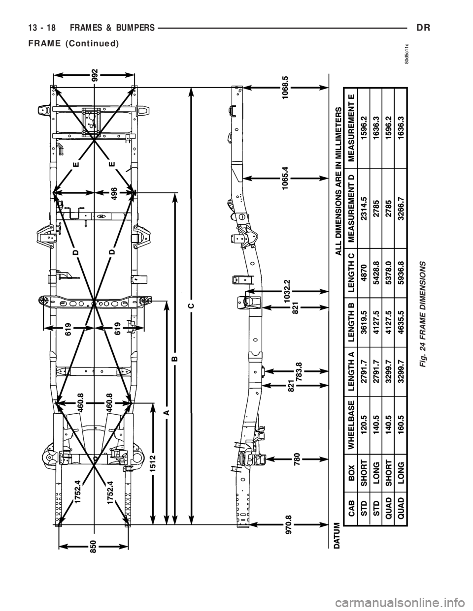
Fig. 24 FRAME DIMENSIONS
13 - 18 FRAMES & BUMPERSDR
FRAME (Continued)
Page 2026 of 2895
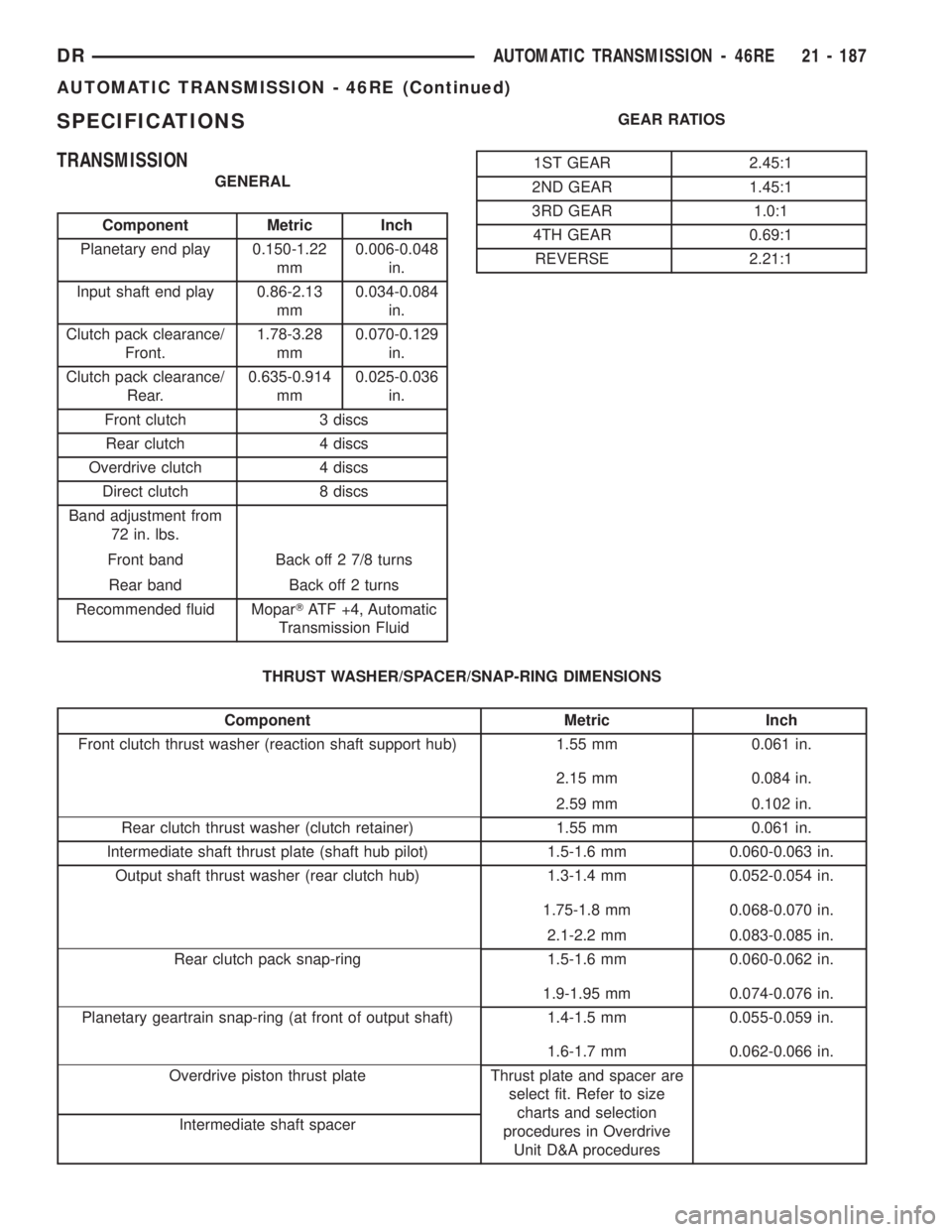
SPECIFICATIONS
TRANSMISSION
GENERAL
Component Metric Inch
Planetary end play 0.150-1.22
mm0.006-0.048
in.
Input shaft end play 0.86-2.13
mm0.034-0.084
in.
Clutch pack clearance/
Front.1.78-3.28
mm0.070-0.129
in.
Clutch pack clearance/
Rear.0.635-0.914
mm0.025-0.036
in.
Front clutch 3 discs
Rear clutch 4 discs
Overdrive clutch 4 discs
Direct clutch 8 discs
Band adjustment from
72 in. lbs.
Front band Back off 2 7/8 turns
Rear band Back off 2 turns
Recommended fluid MoparTATF +4, Automatic
Transmission FluidGEAR RATIOS
1ST GEAR 2.45:1
2ND GEAR 1.45:1
3RD GEAR 1.0:1
4TH GEAR 0.69:1
REVERSE 2.21:1
THRUST WASHER/SPACER/SNAP-RING DIMENSIONS
Component Metric Inch
Front clutch thrust washer (reaction shaft support hub) 1.55 mm 0.061 in.
2.15 mm 0.084 in.
2.59 mm 0.102 in.
Rear clutch thrust washer (clutch retainer) 1.55 mm 0.061 in.
Intermediate shaft thrust plate (shaft hub pilot) 1.5-1.6 mm 0.060-0.063 in.
Output shaft thrust washer (rear clutch hub) 1.3-1.4 mm 0.052-0.054 in.
1.75-1.8 mm 0.068-0.070 in.
2.1-2.2 mm 0.083-0.085 in.
Rear clutch pack snap-ring 1.5-1.6 mm 0.060-0.062 in.
1.9-1.95 mm 0.074-0.076 in.
Planetary geartrain snap-ring (at front of output shaft) 1.4-1.5 mm 0.055-0.059 in.
1.6-1.7 mm 0.062-0.066 in.
Overdrive piston thrust plate Thrust plate and spacer are
select fit. Refer to size
charts and selection
procedures in Overdrive
Unit D&A procedures Intermediate shaft spacer
DRAUTOMATIC TRANSMISSION - 46RE 21 - 187
AUTOMATIC TRANSMISSION - 46RE (Continued)
Page 2207 of 2895
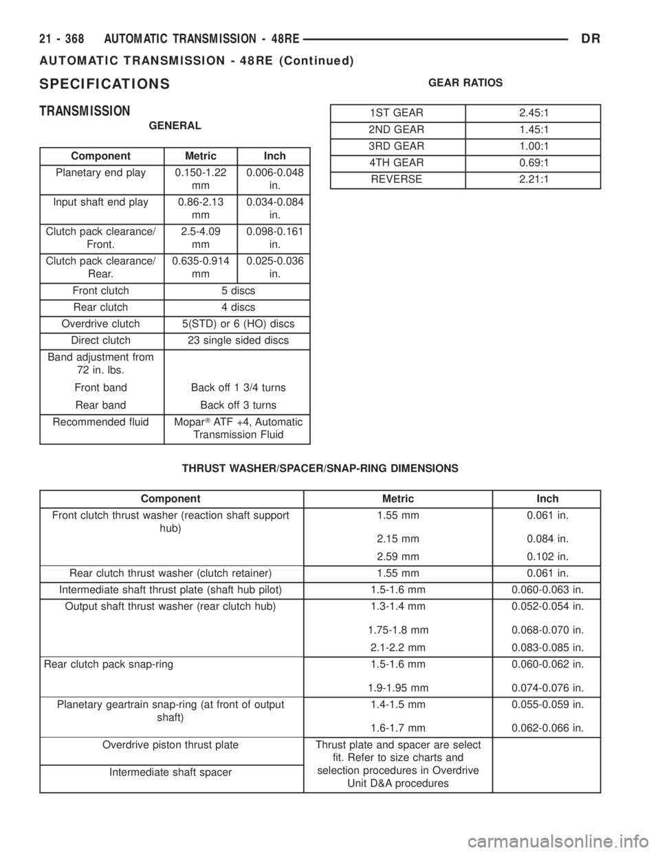
SPECIFICATIONS
TRANSMISSION
GENERAL
Component Metric Inch
Planetary end play 0.150-1.22
mm0.006-0.048
in.
Input shaft end play 0.86-2.13
mm0.034-0.084
in.
Clutch pack clearance/
Front.2.5-4.09
mm0.098-0.161
in.
Clutch pack clearance/
Rear.0.635-0.914
mm0.025-0.036
in.
Front clutch 5 discs
Rear clutch 4 discs
Overdrive clutch 5(STD) or 6 (HO) discs
Direct clutch 23 single sided discs
Band adjustment from
72 in. lbs.
Front band Back off 1 3/4 turns
Rear band Back off 3 turns
Recommended fluid MoparTATF +4, Automatic
Transmission FluidGEAR RATIOS
1ST GEAR 2.45:1
2ND GEAR 1.45:1
3RD GEAR 1.00:1
4TH GEAR 0.69:1
REVERSE 2.21:1
THRUST WASHER/SPACER/SNAP-RING DIMENSIONS
Component Metric Inch
Front clutch thrust washer (reaction shaft support
hub)1.55 mm 0.061 in.
2.15 mm 0.084 in.
2.59 mm 0.102 in.
Rear clutch thrust washer (clutch retainer) 1.55 mm 0.061 in.
Intermediate shaft thrust plate (shaft hub pilot) 1.5-1.6 mm 0.060-0.063 in.
Output shaft thrust washer (rear clutch hub) 1.3-1.4 mm 0.052-0.054 in.
1.75-1.8 mm 0.068-0.070 in.
2.1-2.2 mm 0.083-0.085 in.
Rear clutch pack snap-ring 1.5-1.6 mm 0.060-0.062 in.
1.9-1.95 mm 0.074-0.076 in.
Planetary geartrain snap-ring (at front of output
shaft)1.4-1.5 mm 0.055-0.059 in.
1.6-1.7 mm 0.062-0.066 in.
Overdrive piston thrust plate Thrust plate and spacer are select
fit. Refer to size charts and
selection procedures in Overdrive
Unit D&A procedures Intermediate shaft spacer
21 - 368 AUTOMATIC TRANSMISSION - 48REDR
AUTOMATIC TRANSMISSION - 48RE (Continued)
Page 2670 of 2895

BODY STRUCTURE
TABLE OF CONTENTS
page page
GAP AND FLUSH
SPECIFICATIONS.......................95
OPENING DIMENSIONS
SPECIFICATIONS - BODY OPENING
DIMENSIONS.........................99
SEALER LOCATIONS
SPECIFICATIONS......................103STRUCTURAL ADHESIVE LOCATIONS
SPECIFICATIONS......................113
WELD LOCATIONS
SPECIFICATIONS......................122
GAP AND FLUSH
SPECIFICATIONS
GAP & FLUSH DIMENSIONS INDEX
DESCRIPTION FIGURE
STANDARD CAB 1
QUAD CAB 2
PICKUP BOX 3
DRBODY STRUCTURE 23 - 95
Page 2674 of 2895
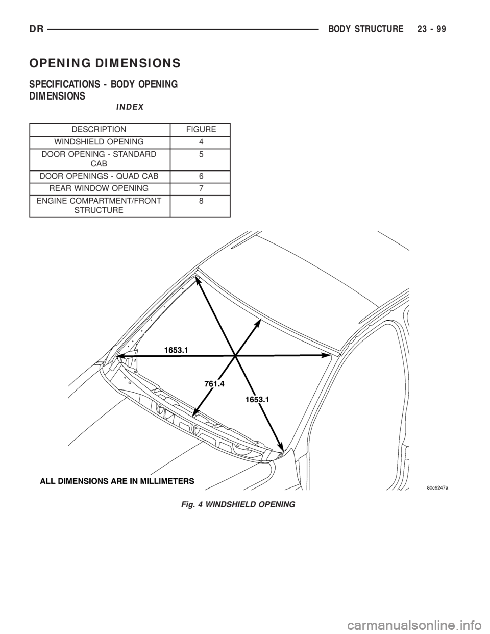
OPENING DIMENSIONS
SPECIFICATIONS - BODY OPENING
DIMENSIONS
INDEX
DESCRIPTION FIGURE
WINDSHIELD OPENING 4
DOOR OPENING - STANDARD
CAB5
DOOR OPENINGS - QUAD CAB 6
REAR WINDOW OPENING 7
ENGINE COMPARTMENT/FRONT
STRUCTURE8
Fig. 4 WINDSHIELD OPENING
DRBODY STRUCTURE 23 - 99