2003 DODGE RAM steering wheel
[x] Cancel search: steering wheelPage 1812 of 2895
GEAR - LINK/COIL
TABLE OF CONTENTS
page page
GEAR - LINK/COIL
DESCRIPTION.........................19
OPERATION...........................19
REMOVAL.............................19
INSTALLATION.........................20
ADJUSTMENTS
ADJUSTMENT........................20
SPECIFICATIONS
POWER STEERING GEAR..............21
TORQUE CHART......................22
SPECIAL TOOLS
POWER STEERING GEAR..............22
PITMAN SHAFT SEAL
REMOVAL
REMOVAL - GAS ENGINE...............23REMOVAL - DIESEL...................24
INSTALLATION
INSTALLATION - GAS ENGINE...........24
INSTALLATION - DIESEL................25
STEERING GEAR INPUT SHAFT SEAL
REMOVAL.............................25
INSTALLATION.........................28
PITMAN SHAFT
REMOVAL
REMOVAL - GAS......................29
REMOVAL - DIESEL...................30
INSTALLATION
INSTALLATION - GAS..................30
INSTALLATION - DIESEL................30
GEAR - LINK/COIL
DESCRIPTION
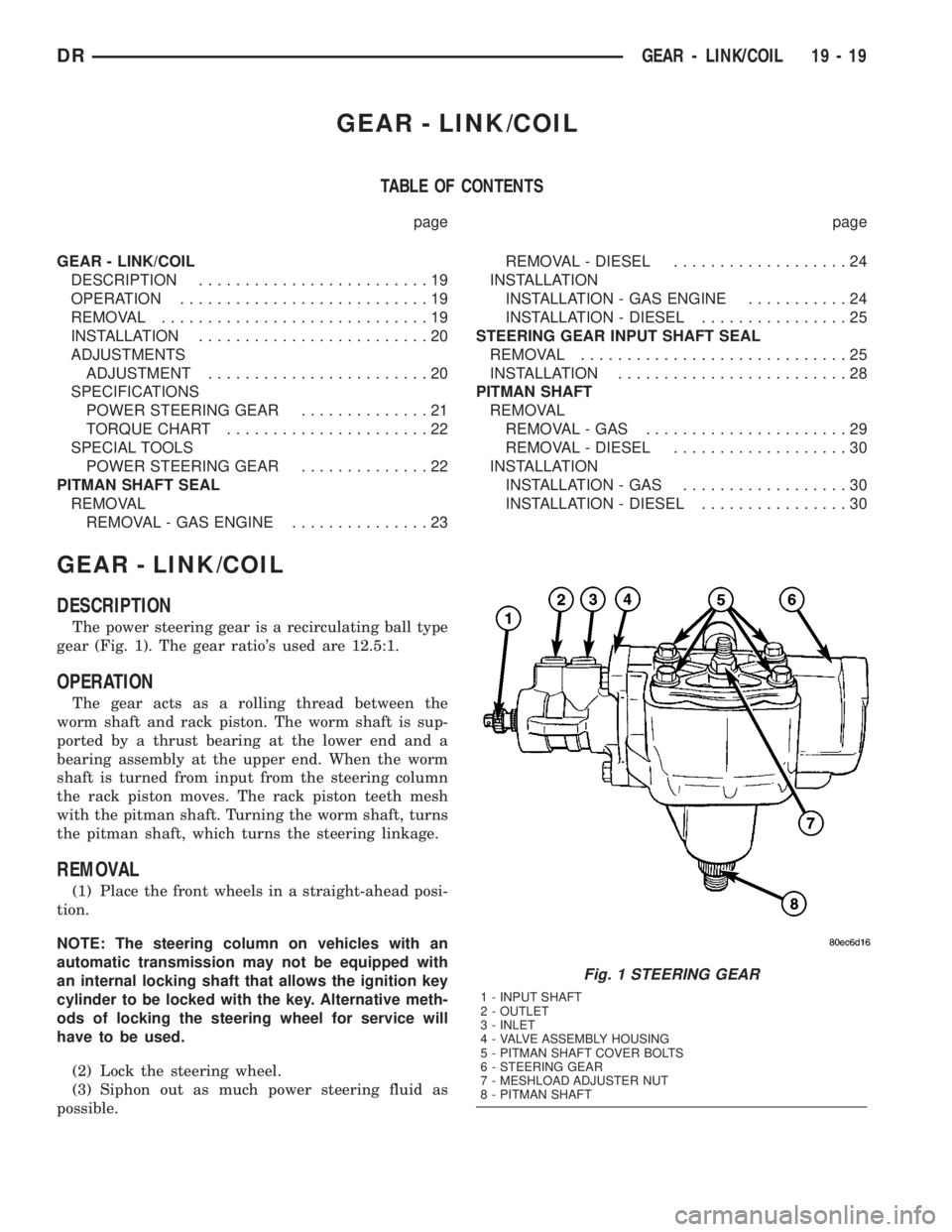
The power steering gear is a recirculating ball type
gear (Fig. 1). The gear ratio's used are 12.5:1.
OPERATION
The gear acts as a rolling thread between the
worm shaft and rack piston. The worm shaft is sup-
ported by a thrust bearing at the lower end and a
bearing assembly at the upper end. When the worm
shaft is turned from input from the steering column
the rack piston moves. The rack piston teeth mesh
with the pitman shaft. Turning the worm shaft, turns
the pitman shaft, which turns the steering linkage.
REMOVAL
(1) Place the front wheels in a straight-ahead posi-
tion.
NOTE: The steering column on vehicles with an
automatic transmission may not be equipped with
an internal locking shaft that allows the ignition key
cylinder to be locked with the key. Alternative meth-
ods of locking the steering wheel for service will
have to be used.
(2) Lock the steering wheel.
(3) Siphon out as much power steering fluid as
possible.
Fig. 1 STEERING GEAR
1 - INPUT SHAFT
2 - OUTLET
3 - INLET
4 - VALVE ASSEMBLY HOUSING
5 - PITMAN SHAFT COVER BOLTS
6 - STEERING GEAR
7 - MESHLOAD ADJUSTER NUT
8 - PITMAN SHAFT
DRGEAR - LINK/COIL 19 - 19
Page 1813 of 2895
(4) Disconnect and cap the fluid hoses from steer-
ing gear (Refer to 19 - STEERING/PUMP/HOSES -
REMOVAL).
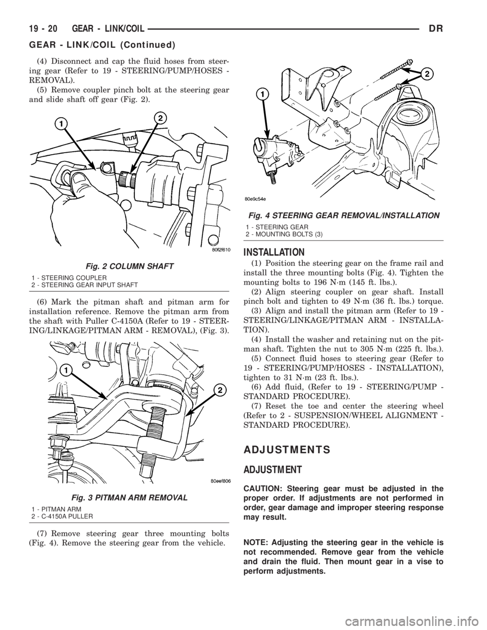
(5) Remove coupler pinch bolt at the steering gear
and slide shaft off gear (Fig. 2).
(6) Mark the pitman shaft and pitman arm for
installation reference. Remove the pitman arm from
the shaft with Puller C-4150A (Refer to 19 - STEER-
ING/LINKAGE/PITMAN ARM - REMOVAL), (Fig. 3).
(7) Remove steering gear three mounting bolts
(Fig. 4). Remove the steering gear from the vehicle.
INSTALLATION
(1) Position the steering gear on the frame rail and
install the three mounting bolts (Fig. 4). Tighten the
mounting bolts to 196 N´m (145 ft. lbs.).
(2) Align steering coupler on gear shaft. Install
pinch bolt and tighten to 49 N´m (36 ft. lbs.) torque.
(3) Align and install the pitman arm (Refer to 19 -
STEERING/LINKAGE/PITMAN ARM - INSTALLA-
TION).
(4) Install the washer and retaining nut on the pit-
man shaft. Tighten the nut to 305 N´m (225 ft. lbs.).
(5) Connect fluid hoses to steering gear (Refer to
19 - STEERING/PUMP/HOSES - INSTALLATION),
tighten to 31 N´m (23 ft. lbs.).
(6) Add fluid, (Refer to 19 - STEERING/PUMP -
STANDARD PROCEDURE).
(7) Reset the toe and center the steering wheel
(Refer to 2 - SUSPENSION/WHEEL ALIGNMENT -
STANDARD PROCEDURE).
ADJUSTMENTS
ADJUSTMENT
CAUTION: Steering gear must be adjusted in the
proper order. If adjustments are not performed in
order, gear damage and improper steering response
may result.
NOTE: Adjusting the steering gear in the vehicle is
not recommended. Remove gear from the vehicle
and drain the fluid. Then mount gear in a vise to
perform adjustments.
Fig. 2 COLUMN SHAFT
1 - STEERING COUPLER
2 - STEERING GEAR INPUT SHAFT
Fig. 3 PITMAN ARM REMOVAL
1 - PITMAN ARM
2 - C-4150A PULLER
Fig. 4 STEERING GEAR REMOVAL/INSTALLATION
1 - STEERING GEAR
2 - MOUNTING BOLTS (3)
19 - 20 GEAR - LINK/COILDR
GEAR - LINK/COIL (Continued)
Page 1816 of 2895
PITMAN SHAFT SEAL
REMOVAL
REMOVAL - GAS ENGINE
(1) Seperate the pitman arm from the gear box
(Refer to 19 - STEERING/LINKAGE/PITMAN ARM -
REMOVAL).
(2) Clean exposed end of pitman shaft and housing
with a wire brush.
(3) Rotate the steering wheel from stop to stop and
count the number of turns.
(4) Center the steering wheel by rotating it from
the stop back 1 1/2 turns to achieve center position.
(5) Remove the pitman shaft cover bolts.
NOTE: The pitman shaft will not clear the housing if
it is not centered.
(6) Remove the pitman shaft from the gear.
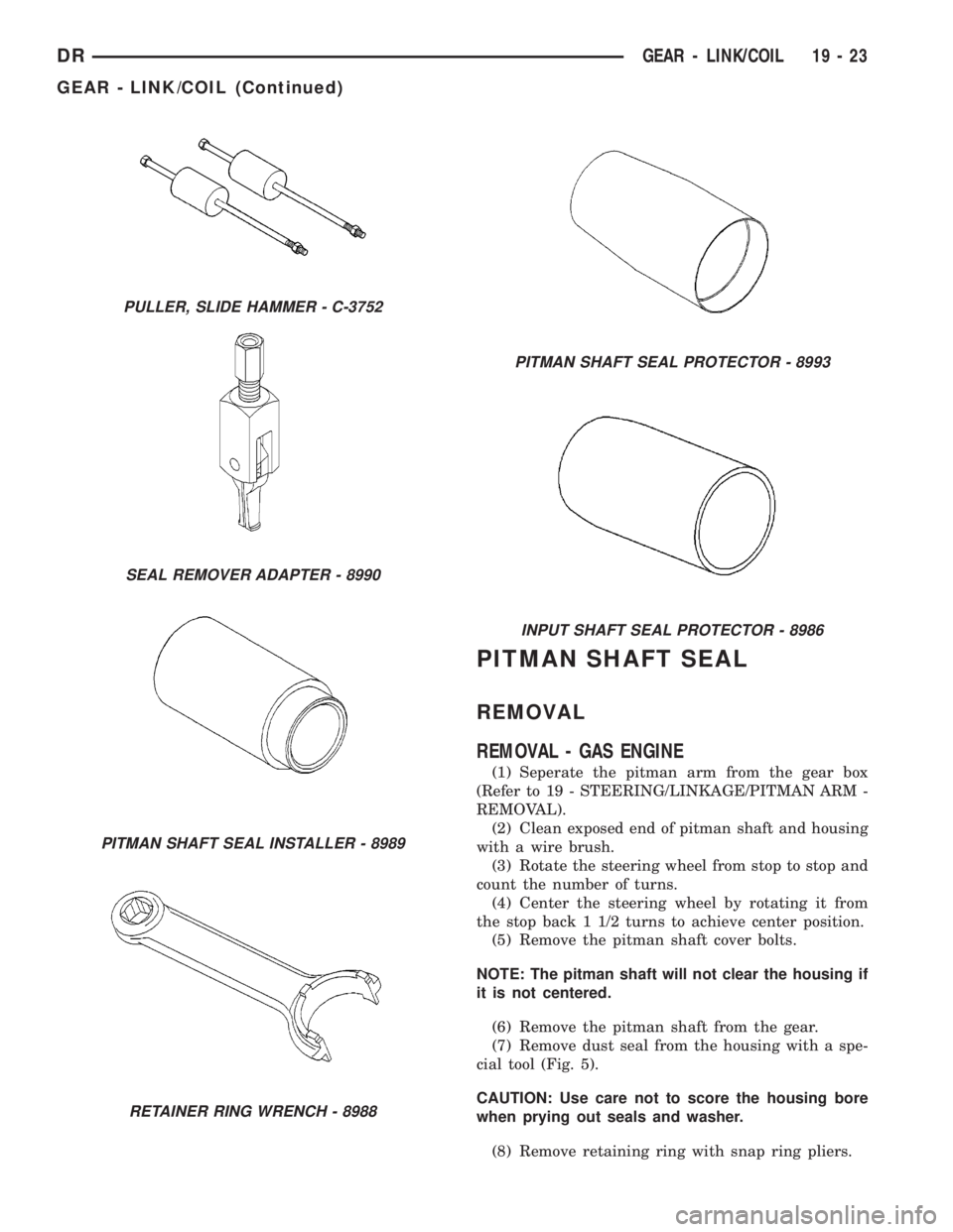
(7) Remove dust seal from the housing with a spe-
cial tool (Fig. 5).
CAUTION: Use care not to score the housing bore
when prying out seals and washer.
(8) Remove retaining ring with snap ring pliers.
PULLER, SLIDE HAMMER - C-3752
SEAL REMOVER ADAPTER - 8990
PITMAN SHAFT SEAL INSTALLER - 8989
RETAINER RING WRENCH - 8988
PITMAN SHAFT SEAL PROTECTOR - 8993
INPUT SHAFT SEAL PROTECTOR - 8986
DRGEAR - LINK/COIL 19 - 23
GEAR - LINK/COIL (Continued)
Page 1818 of 2895
(5) Coat the dust seal withhigh temp grease.
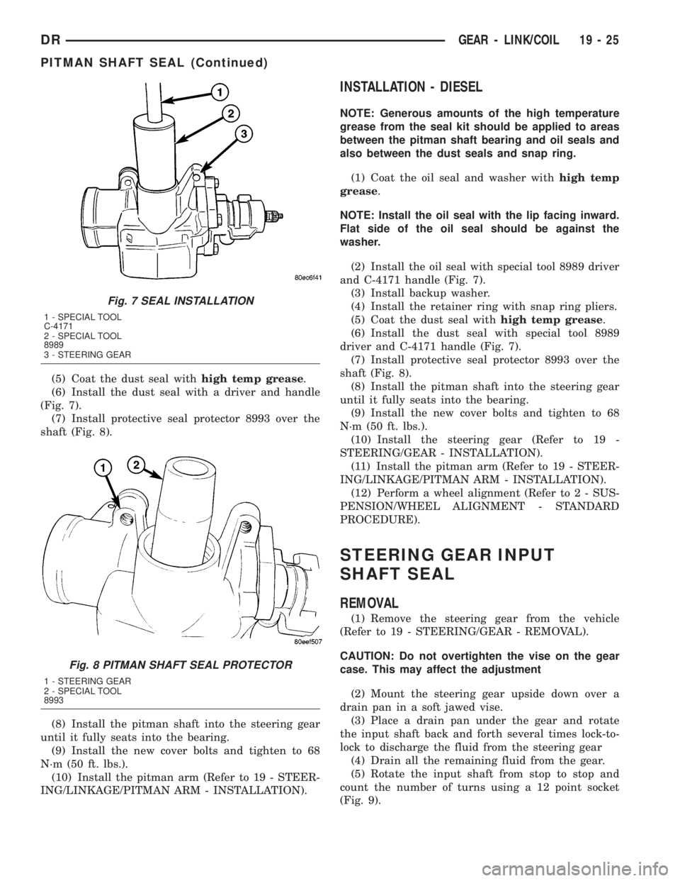
(6) Install the dust seal with a driver and handle
(Fig. 7).
(7) Install protective seal protector 8993 over the
shaft (Fig. 8).
(8) Install the pitman shaft into the steering gear
until it fully seats into the bearing.
(9) Install the new cover bolts and tighten to 68
N´m (50 ft. lbs.).
(10) Install the pitman arm (Refer to 19 - STEER-
ING/LINKAGE/PITMAN ARM - INSTALLATION).
INSTALLATION - DIESEL
NOTE: Generous amounts of the high temperature
grease from the seal kit should be applied to areas
between the pitman shaft bearing and oil seals and
also between the dust seals and snap ring.
(1) Coat the oil seal and washer withhigh temp
grease.
NOTE: Install the oil seal with the lip facing inward.
Flat side of the oil seal should be against the
washer.
(2) Install the oil seal with special tool 8989 driver
and C-4171 handle (Fig. 7).
(3) Install backup washer.
(4) Install the retainer ring with snap ring pliers.
(5) Coat the dust seal withhigh temp grease.
(6) Install the dust seal with special tool 8989
driver and C-4171 handle (Fig. 7).
(7) Install protective seal protector 8993 over the
shaft (Fig. 8).
(8) Install the pitman shaft into the steering gear
until it fully seats into the bearing.
(9) Install the new cover bolts and tighten to 68
N´m (50 ft. lbs.).
(10) Install the steering gear (Refer to 19 -
STEERING/GEAR - INSTALLATION).
(11) Install the pitman arm (Refer to 19 - STEER-
ING/LINKAGE/PITMAN ARM - INSTALLATION).
(12) Perform a wheel alignment (Refer to 2 - SUS-
PENSION/WHEEL ALIGNMENT - STANDARD
PROCEDURE).
STEERING GEAR INPUT
SHAFT SEAL
REMOVAL
(1) Remove the steering gear from the vehicle
(Refer to 19 - STEERING/GEAR - REMOVAL).
CAUTION: Do not overtighten the vise on the gear
case. This may affect the adjustment
(2) Mount the steering gear upside down over a
drain pan in a soft jawed vise.
(3) Place a drain pan under the gear and rotate
the input shaft back and forth several times lock-to-
lock to discharge the fluid from the steering gear
(4) Drain all the remaining fluid from the gear.
(5) Rotate the input shaft from stop to stop and
count the number of turns using a 12 point socket
(Fig. 9).
Fig. 7 SEAL INSTALLATION
1 - SPECIAL TOOL
C-4171
2 - SPECIAL TOOL
8989
3 - STEERING GEAR
Fig. 8 PITMAN SHAFT SEAL PROTECTOR
1 - STEERING GEAR
2 - SPECIAL TOOL
8993
DRGEAR - LINK/COIL 19 - 25
PITMAN SHAFT SEAL (Continued)
Page 1822 of 2895
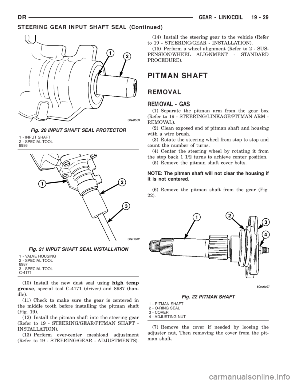
(10) Install the new dust seal usinghigh temp
grease, special tool C-4171 (driver) and 8987 (han-
dle).
(11) Check to make sure the gear is centered in
the middle tooth before installing the pitman shaft
(Fig. 19).
(12) Install the pitman shaft into the steering gear
(Refer to 19 - STEERING/GEAR/PITMAN SHAFT -
INSTALLATION).
(13) Perform over-center meshload adjustment
(Refer to 19 - STEERING/GEAR - ADJUSTMENTS).(14) Install the steering gear to the vehicle (Refer
to 19 - STEERING/GEAR - INSTALLATION).
(15) Perform a wheel alignment (Refer to 2 - SUS-
PENSION/WHEEL ALIGNMENT - STANDARD
PROCEDURE).
PITMAN SHAFT
REMOVAL
REMOVAL - GAS
(1) Separate the pitman arm from the gear box
(Refer to 19 - STEERING/LINKAGE/PITMAN ARM -
REMOVAL).
(2) Clean exposed end of pitman shaft and housing
with a wire brush.
(3) Rotate the steering wheel from stop to stop and
count the number of turns.
(4) Center the steering wheel by rotating it from
the stop back 1 1/2 turns to achieve center position.
(5) Remove the pitman shaft cover bolts.
NOTE: The pitman shaft will not clear the housing if
it is not centered.
(6) Remove the pitman shaft from the gear (Fig.
22).
(7) Remove the cover if needed by loosing the
adjuster nut, Then removing the cover from the pit-
man shaft.
Fig. 20 INPUT SHAFT SEAL PROTECTOR
1 - INPUT SHAFT
2 - SPECIAL TOOL
8986
Fig. 21 INPUT SHAFT SEAL INSTALLATION
1 - VALVE HOUSING
2 - SPECIAL TOOL
8987
3 - SPECIAL TOOL
C-4171
Fig. 22 PITMAN SHAFT
1 - PITMAN SHAFT
2 - O-RING SEAL
3 - COVER
4 - ADJUSTING NUT
DRGEAR - LINK/COIL 19 - 29
STEERING GEAR INPUT SHAFT SEAL (Continued)
Page 1823 of 2895
REMOVAL - DIESEL
(1) Separate the pitman arm from the gear box
(Refer to 19 - STEERING/LINKAGE/PITMAN ARM -
REMOVAL).
(2) Remove the steering gear box (Refer to 19 -
STEERING/GEAR - REMOVAL).
(3) Install the steering gear in a soft jawed bench
vise.
(4) Clean exposed end of pitman shaft and housing
with a wire brush.
(5) Rotate the stub shaft with a 12 point socket
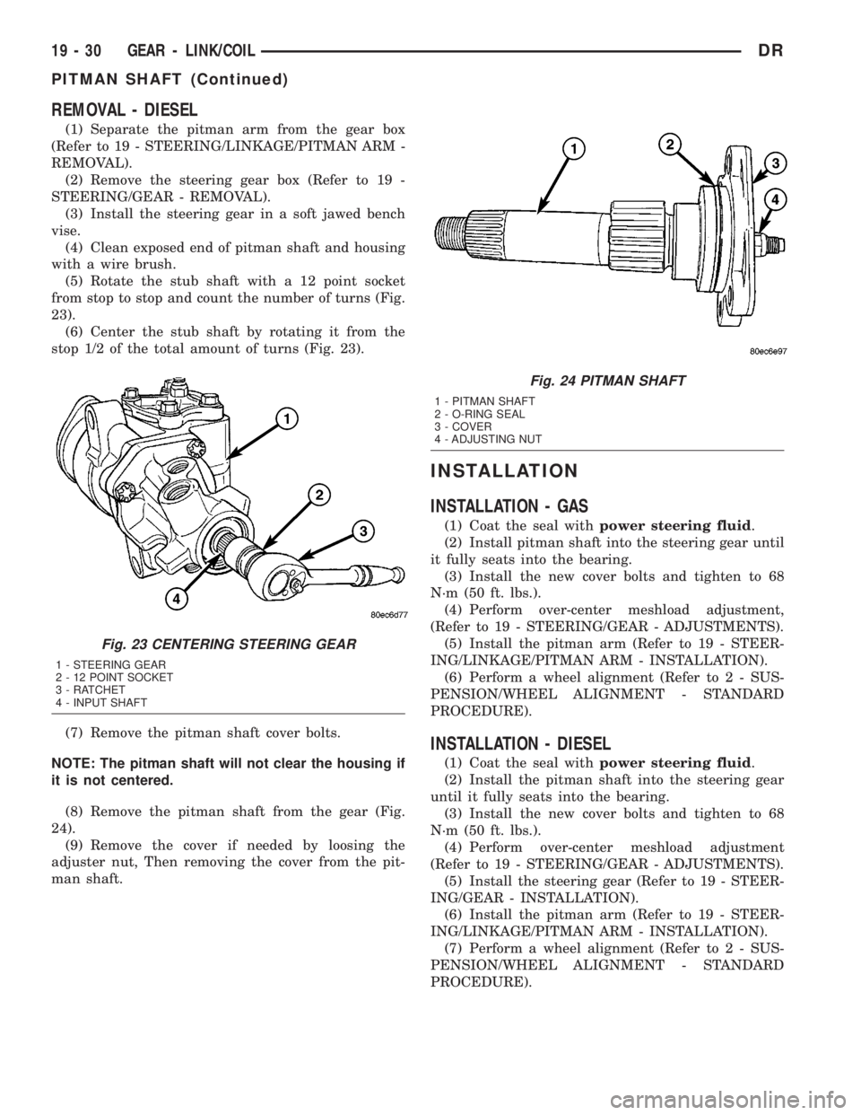
from stop to stop and count the number of turns (Fig.
23).
(6) Center the stub shaft by rotating it from the
stop 1/2 of the total amount of turns (Fig. 23).
(7) Remove the pitman shaft cover bolts.
NOTE: The pitman shaft will not clear the housing if
it is not centered.
(8) Remove the pitman shaft from the gear (Fig.
24).
(9) Remove the cover if needed by loosing the
adjuster nut, Then removing the cover from the pit-
man shaft.
INSTALLATION
INSTALLATION - GAS
(1) Coat the seal withpower steering fluid.
(2) Install pitman shaft into the steering gear until
it fully seats into the bearing.
(3) Install the new cover bolts and tighten to 68
N´m (50 ft. lbs.).
(4) Perform over-center meshload adjustment,
(Refer to 19 - STEERING/GEAR - ADJUSTMENTS).
(5) Install the pitman arm (Refer to 19 - STEER-
ING/LINKAGE/PITMAN ARM - INSTALLATION).
(6) Perform a wheel alignment (Refer to 2 - SUS-
PENSION/WHEEL ALIGNMENT - STANDARD
PROCEDURE).
INSTALLATION - DIESEL
(1) Coat the seal withpower steering fluid.
(2) Install the pitman shaft into the steering gear
until it fully seats into the bearing.
(3) Install the new cover bolts and tighten to 68
N´m (50 ft. lbs.).
(4) Perform over-center meshload adjustment
(Refer to 19 - STEERING/GEAR - ADJUSTMENTS).
(5) Install the steering gear (Refer to 19 - STEER-
ING/GEAR - INSTALLATION).
(6) Install the pitman arm (Refer to 19 - STEER-
ING/LINKAGE/PITMAN ARM - INSTALLATION).
(7) Perform a wheel alignment (Refer to 2 - SUS-
PENSION/WHEEL ALIGNMENT - STANDARD
PROCEDURE).
Fig. 23 CENTERING STEERING GEAR
1 - STEERING GEAR
2 - 12 POINT SOCKET
3 - RATCHET
4 - INPUT SHAFT
Fig. 24 PITMAN SHAFT
1 - PITMAN SHAFT
2 - O-RING SEAL
3 - COVER
4 - ADJUSTING NUT
19 - 30 GEAR - LINK/COILDR
PITMAN SHAFT (Continued)
Page 1824 of 2895
LINKAGE - INDEPENDENT FRONT SUSPENSION
TABLE OF CONTENTS
page page
LINKAGE - INDEPENDENT FRONT
SUSPENSION
DIAGNOSIS AND TESTING - OUTER TIE ROD
END ................................31TIE ROD END
REMOVAL - OUTER TIE ROD END..........31
INSTALLATION - OUTER TIE ROD END......32
LINKAGE - INDEPENDENT
FRONT SUSPENSION
DIAGNOSIS AND TESTING - OUTER TIE ROD
END
NOTE: If the outer tie rod end is equipped with a
lubrication fitting, grease the joint then road test
the vehicle before performing test.
(1) Raise the front of the vehicle. Place safety floor
stands under both lower control arms as far outboard
as possible. Lower the vehicle to allow the stands to
support some or all of the vehicle weight.
(2) Remove the front tires.
(3) Mount a dial indicator solidly to the vehicle
steering knuckle and then zero the dial indicator.
(4) Position indicator plunger on the topside of the
outer tie rod end.
NOTE: The dial indicator plunger must be perpen-
dicular to the machined surface of the outer tie rod
end.
(5) Position a pry bar in order to pry downwards
on the outer tie rod end.
(6) If the travel exceeds 0.5 mm (0.020 in.), replace
the outer tie rod end (Refer to 19 - STEERING/
LINKAGE/TIE ROD END - REMOVAL).
(7) If the outer tie rod end is within specs reinstall
the front tires (Refer to 22 - TIRES/WHEELS/
WHEELS - STANDARD PROCEDURE).
TIE ROD END
REMOVAL - OUTER TIE ROD END
NOTE: Do not twist the boot anytime during
removal or installation.
(1) Loosen the jam nut.
(2) Remove the outer tie rod end nut from the ball
stud.
(3) Separate the tie rod ball stud from the knuckle
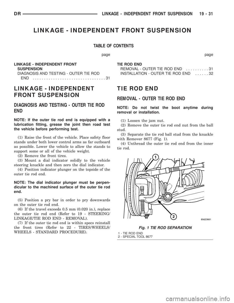
with Remover 8677 (Fig. 1).
(4) Unthread the outer tie rod end from the inner
tie rod.
Fig. 1 TIE ROD SEPARATION
1 - TIE ROD END
2 - SPECIAL TOOL 8677
DRLINKAGE - INDEPENDENT FRONT SUSPENSION 19 - 31
Page 1825 of 2895
INSTALLATION - OUTER TIE ROD END
NOTE: Do not twist the boot at anytime during
removal or installation.
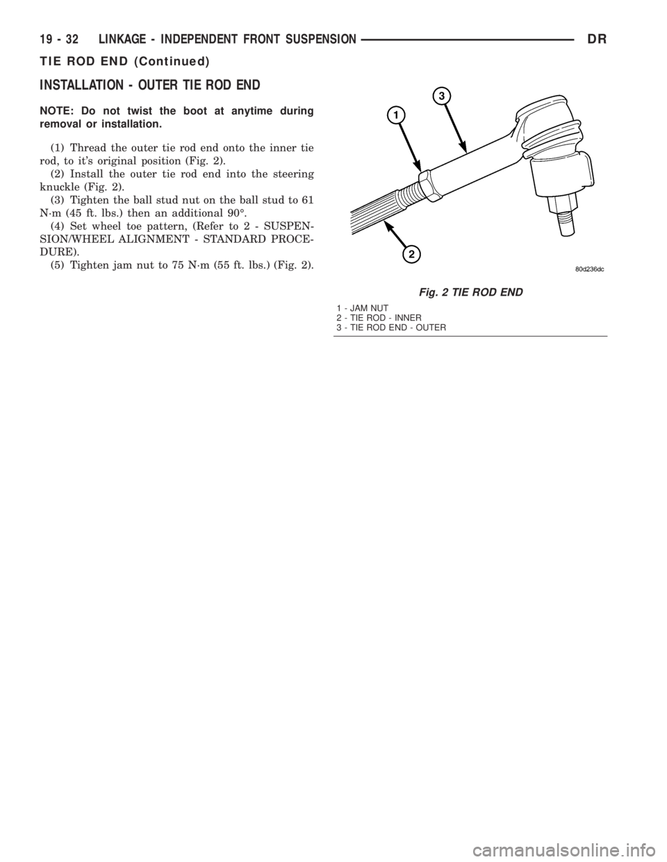
(1) Thread the outer tie rod end onto the inner tie
rod, to it's original position (Fig. 2).
(2) Install the outer tie rod end into the steering
knuckle (Fig. 2).
(3) Tighten the ball stud nut on the ball stud to 61
N´m (45 ft. lbs.) then an additional 90É.
(4) Set wheel toe pattern, (Refer to 2 - SUSPEN-
SION/WHEEL ALIGNMENT - STANDARD PROCE-
DURE).
(5) Tighten jam nut to 75 N´m (55 ft. lbs.) (Fig. 2).
Fig. 2 TIE ROD END
1 - JAM NUT
2 - TIE ROD - INNER
3 - TIE ROD END - OUTER
19 - 32 LINKAGE - INDEPENDENT FRONT SUSPENSIONDR
TIE ROD END (Continued)