2003 DODGE RAM steering wheel
[x] Cancel search: steering wheelPage 1828 of 2895
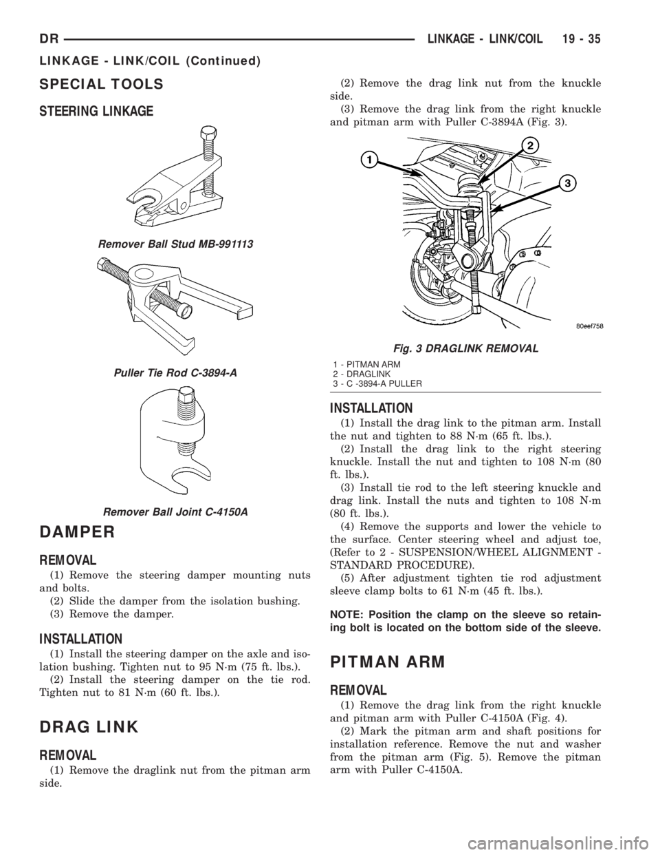
SPECIAL TOOLS
STEERING LINKAGE
DAMPER
REMOVAL
(1) Remove the steering damper mounting nuts
and bolts.
(2) Slide the damper from the isolation bushing.
(3) Remove the damper.
INSTALLATION
(1) Install the steering damper on the axle and iso-
lation bushing. Tighten nut to 95 N´m (75 ft. lbs.).
(2) Install the steering damper on the tie rod.
Tighten nut to 81 N´m (60 ft. lbs.).
DRAG LINK
REMOVAL
(1) Remove the draglink nut from the pitman arm
side.(2) Remove the drag link nut from the knuckle
side.
(3) Remove the drag link from the right knuckle
and pitman arm with Puller C-3894A (Fig. 3).
INSTALLATION
(1) Install the drag link to the pitman arm. Install
the nut and tighten to 88 N´m (65 ft. lbs.).
(2) Install the drag link to the right steering
knuckle. Install the nut and tighten to 108 N´m (80
ft. lbs.).
(3) Install tie rod to the left steering knuckle and
drag link. Install the nuts and tighten to 108 N´m
(80 ft. lbs.).
(4) Remove the supports and lower the vehicle to
the surface. Center steering wheel and adjust toe,
(Refer to 2 - SUSPENSION/WHEEL ALIGNMENT -
STANDARD PROCEDURE).
(5) After adjustment tighten tie rod adjustment
sleeve clamp bolts to 61 N´m (45 ft. lbs.).
NOTE: Position the clamp on the sleeve so retain-
ing bolt is located on the bottom side of the sleeve.
PITMAN ARM
REMOVAL
(1) Remove the drag link from the right knuckle
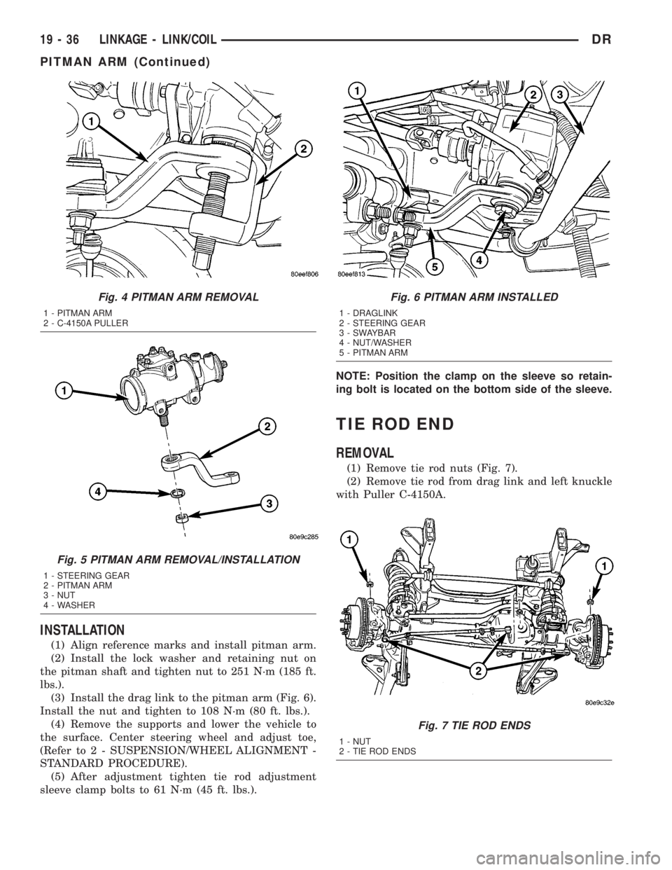
and pitman arm with Puller C-4150A (Fig. 4).
(2) Mark the pitman arm and shaft positions for
installation reference. Remove the nut and washer
from the pitman arm (Fig. 5). Remove the pitman
arm with Puller C-4150A.
Remover Ball Stud MB-991113
Puller Tie Rod C-3894-A
Remover Ball Joint C-4150A
Fig. 3 DRAGLINK REMOVAL
1 - PITMAN ARM
2 - DRAGLINK
3 - C -3894-A PULLER
DRLINKAGE - LINK/COIL 19 - 35
LINKAGE - LINK/COIL (Continued)
Page 1829 of 2895
INSTALLATION
(1) Align reference marks and install pitman arm.
(2) Install the lock washer and retaining nut on
the pitman shaft and tighten nut to 251 N´m (185 ft.
lbs.).
(3) Install the drag link to the pitman arm (Fig. 6).
Install the nut and tighten to 108 N´m (80 ft. lbs.).
(4) Remove the supports and lower the vehicle to
the surface. Center steering wheel and adjust toe,
(Refer to 2 - SUSPENSION/WHEEL ALIGNMENT -
STANDARD PROCEDURE).
(5) After adjustment tighten tie rod adjustment
sleeve clamp bolts to 61 N´m (45 ft. lbs.).NOTE: Position the clamp on the sleeve so retain-
ing bolt is located on the bottom side of the sleeve.
TIE ROD END
REMOVAL
(1) Remove tie rod nuts (Fig. 7).
(2) Remove tie rod from drag link and left knuckle
with Puller C-4150A.
Fig. 4 PITMAN ARM REMOVAL
1 - PITMAN ARM
2 - C-4150A PULLER
Fig. 5 PITMAN ARM REMOVAL/INSTALLATION
1 - STEERING GEAR
2 - PITMAN ARM
3 - NUT
4 - WASHER
Fig. 6 PITMAN ARM INSTALLED
1 - DRAGLINK
2 - STEERING GEAR
3 - SWAYBAR
4 - NUT/WASHER
5 - PITMAN ARM
Fig. 7 TIE ROD ENDS
1 - NUT
2 - TIE ROD ENDS
19 - 36 LINKAGE - LINK/COILDR
PITMAN ARM (Continued)
Page 1830 of 2895
INSTALLATION
(1) Install tie rod to the left steering knuckle and
drag link. Install the nuts and tighten to 108 N´m
(80 ft. lbs.).
(2) Remove the supports and lower the vehicle to
the surface. Center steering wheel and adjust toe,
(Refer to 2 - SUSPENSION/WHEEL ALIGNMENT -
STANDARD PROCEDURE).
(3) After adjustment tighten tie rod adjustment
sleeve clamp bolts to 61 N´m (45 ft. lbs.).
NOTE: Position the clamp on the sleeve so retain-
ing bolt is located on the bottom side of the sleeve.
TRACK BAR
REMOVAL
(1) Raise and support the axle.
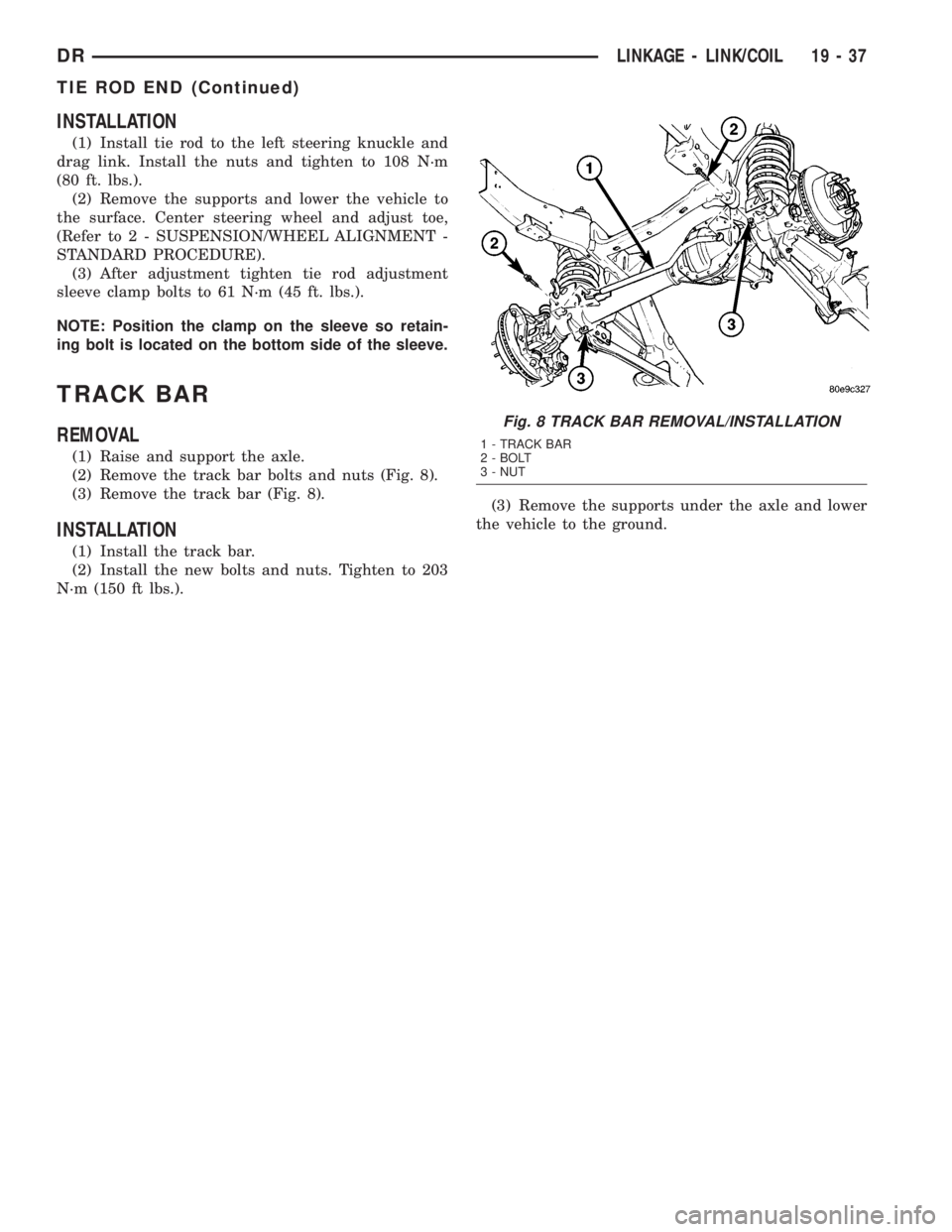
(2) Remove the track bar bolts and nuts (Fig. 8).
(3) Remove the track bar (Fig. 8).
INSTALLATION
(1) Install the track bar.
(2) Install the new bolts and nuts. Tighten to 203
N´m (150 ft lbs.).(3) Remove the supports under the axle and lower
the vehicle to the ground.
Fig. 8 TRACK BAR REMOVAL/INSTALLATION
1 - TRACK BAR
2 - BOLT
3 - NUT
DRLINKAGE - LINK/COIL 19 - 37
TIE ROD END (Continued)
Page 1832 of 2895
DIAGNOSIS AND TESTING - PUMP LEAKAGE
The pump is serviced as an assembly and should
not be disassembled. The plastic pump reservoir and
the reservoir o-rings can be replaced.
Check for leaks in the following areas:
²Pump shaft seal behind the pulley
²Pump to reservoir O-ring
²Reservoir cap
²Pressure and return lines
²Flow control valve fitting
STANDARD PROCEDURE
STANDARD PROCEDURE - POWER STEERING
PUMP - INITIAL OPERATION
WARNING: THE FLUID LEVEL SHOULD BE
CHECKED WITH ENGINE OFF TO PREVENT INJURY
FROM MOVING COMPONENTS.
CAUTION: MOPARTATF+4 is to be used in the
power steering system. No other power steering or
automatic transmission fluid is to be used in the
system. Damage may result to the power steering
pump and system if any other fluid is used, and do
not overfill.
Wipe filler cap clean, then check the fluid level.
The dipstick should indicateCOLDwhen the fluid is
at normal temperature.(1) Turn steering wheel all the way to the left
(2) Fill the pump fluid reservoir to the proper level
and let the fluid settle for at least two (2) minutes.
(3) Raise the front wheels off the ground.
(4) Slowly turn the steering wheel lock-to-lock 20
times with the engine off while checking the fluid
level.
NOTE: For vehicles with long return lines or oil
coolers turn wheel 40 times.
(5) Start the engine. With the engine idling main-
tain the fluid level.
(6) Lower the front wheels and let the engine idle
for two minutes.
(7) Turn the steering wheel in both direction and
verify power assist and quiet operation of the pump.
If the fluid is extremely foamy or milky looking,
allow the vehicle to stand a few minutes and repeat
the procedure.
CAUTION: Do not run a vehicle with foamy fluid for
an extended period. This may cause pump damage.
STANDARD PROCEDURE - FLUSHING POWER
STEERING SYSTEM
Flushing is required when the power steering/hy-
draulic booster system fluid has become contami-
nated. Contaminated fluid in the steering/booster
system can cause seal deterioration and affect steer-
ing gear/booster spool valve operation.
(1) Raise the front end of the vehicle off the
ground until the wheels are free to turn.
(2) Remove the return line from the pump.
NOTE: If vehicle is equipped with a hydraulic
booster remove both return lines from the pump.
(3) Plug the return line port/ports at the pump.
(4) Position the return line/lines into a large con-
tainer to catch the fluid.
(5) While an assistant is filling the pump reservoir
start the engine.
(6) With the engine running at idle turn the wheel
back and forth.
NOTE: Do not contact or hold the wheel against the
steering stops.
(7) Run a quart of fluid through the system then
stop the engine and install the return line/lines.
(8) Fill the system with fluid and perform Steering
Pump Initial Operation, (Refer to 19 - STEERING/
PUMP - STANDARD PROCEDURE).
(9) Start the engine and run it for fifteen minutes
then stop the engine.
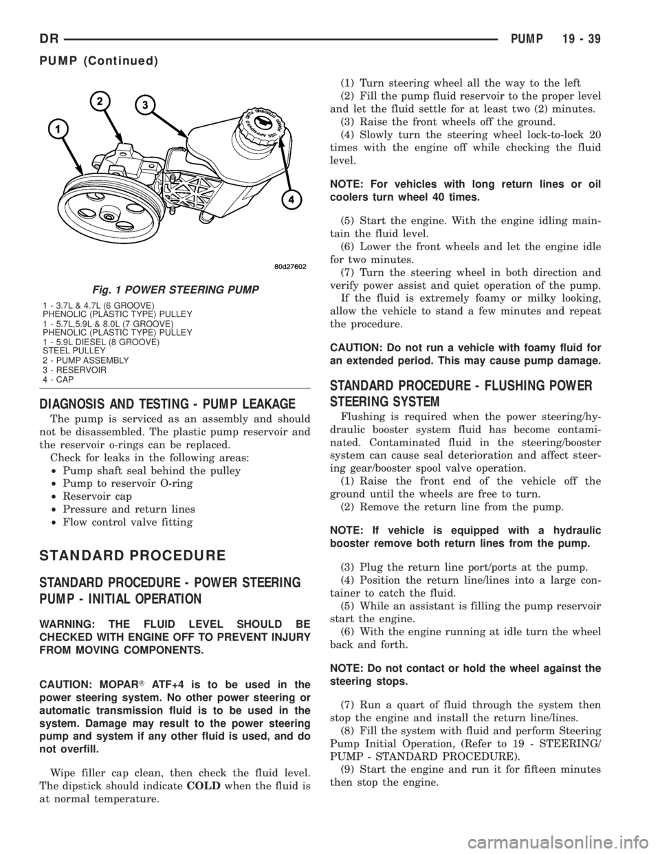
Fig. 1 POWER STEERING PUMP
1 - 3.7L & 4.7L (6 GROOVE)
PHENOLIC (PLASTIC TYPE) PULLEY
1 - 5.7L,5.9L & 8.0L (7 GROOVE)
PHENOLIC (PLASTIC TYPE) PULLEY
1 - 5.9L DIESEL (8 GROOVE)
STEEL PULLEY
2 - PUMP ASSEMBLY
3 - RESERVOIR
4 - CAP
DRPUMP 19 - 39
PUMP (Continued)
Page 2561 of 2895
METHOD 2 (RELOCATE TIRE ON WHEEL)
NOTE: Rotating the tire on wheel is particularly
effective when there is runout in both tire and
wheel.
(1) Remove tire from wheel and mount wheel on
service dynamic balance machine.
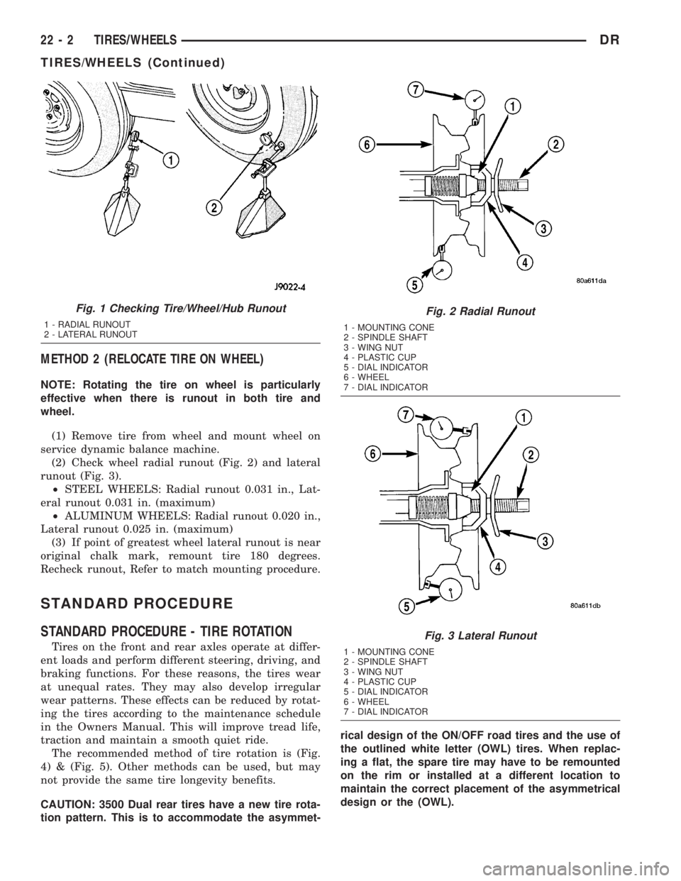
(2) Check wheel radial runout (Fig. 2) and lateral
runout (Fig. 3).
²STEEL WHEELS: Radial runout 0.031 in., Lat-
eral runout 0.031 in. (maximum)
²ALUMINUM WHEELS: Radial runout 0.020 in.,
Lateral runout 0.025 in. (maximum)
(3) If point of greatest wheel lateral runout is near
original chalk mark, remount tire 180 degrees.
Recheck runout, Refer to match mounting procedure.
STANDARD PROCEDURE
STANDARD PROCEDURE - TIRE ROTATION
Tires on the front and rear axles operate at differ-
ent loads and perform different steering, driving, and
braking functions. For these reasons, the tires wear
at unequal rates. They may also develop irregular
wear patterns. These effects can be reduced by rotat-
ing the tires according to the maintenance schedule
in the Owners Manual. This will improve tread life,
traction and maintain a smooth quiet ride.
The recommended method of tire rotation is (Fig.
4) & (Fig. 5). Other methods can be used, but may
not provide the same tire longevity benefits.
CAUTION: 3500 Dual rear tires have a new tire rota-
tion pattern. This is to accommodate the asymmet-rical design of the ON/OFF road tires and the use of
the outlined white letter (OWL) tires. When replac-
ing a flat, the spare tire may have to be remounted
on the rim or installed at a different location to
maintain the correct placement of the asymmetrical
design or the (OWL).
Fig. 1 Checking Tire/Wheel/Hub Runout
1 - RADIAL RUNOUT
2 - LATERAL RUNOUT
Fig. 2 Radial Runout
1 - MOUNTING CONE
2 - SPINDLE SHAFT
3 - WING NUT
4 - PLASTIC CUP
5 - DIAL INDICATOR
6 - WHEEL
7 - DIAL INDICATOR
Fig. 3 Lateral Runout
1 - MOUNTING CONE
2 - SPINDLE SHAFT
3 - WING NUT
4 - PLASTIC CUP
5 - DIAL INDICATOR
6 - WHEEL
7 - DIAL INDICATOR
22 - 2 TIRES/WHEELSDR
TIRES/WHEELS (Continued)
Page 2565 of 2895
TIRE CHAINS
Tire snow chains may be used oncertainmodels.
Refer to the Owner's Manual for more information.
DESCRIPTION - RADIAL ± PLY TIRES
Radial-ply tires improve handling, tread life and
ride quality, and decrease rolling resistance.
Radial-ply tires must always be used in sets of
four. Under no circumstances should they be used on
the front only. They may be mixed with temporary
spare tires when necessary. A maximum speed of 50
MPH is recommended while a temporary spare is in
use.
Radial-ply tires have the same load-carrying capac-
ity as other types of tires of the same size. They also
use the same recommended inflation pressures.
The use of oversized tires, either in the front or
rear of the vehicle, can cause vehicle drive train fail-
ure. This could also cause inaccurate wheel speed
signals when the vehicle is equipped with Anti-Lock
Brakes.
The use of tires from different manufactures on the
same vehicle is NOT recommended. The proper tire
pressure should be maintained on all four tires.
DESCRIPTION - TIRE PRESSURE FOR HIGH
SPEEDS
Where speed limits allow the vehicle to be driven at
high speeds, correct tire inflation pressure is very
important. For speeds up to and including 120 km/h (75
mph), tires must be inflated to the pressures shown on
the tire placard. For continuous speeds in excess of 120
km/h (75 mph), tires must be inflated to the maximum
pressure specified on the tire sidewall.
Vehicles loaded to the maximum capacity should not
be driven at continuous speeds above 75 mph (120
km/h).
For emergency vehicles that are driven at speeds
over 90 mph (144 km/h), special high speed tires
must be used. Consult tire manufacturer for correct
inflation pressure recommendations.
DESCRIPTION - REPLACEMENT TIRES
The original equipment tires provide a proper bal-
ance of many characteristics such as:
²Ride
²Noise
²Handling
²Durability
²Tread life
²Traction
²Rolling resistance
²Speed capability
It is recommended that tires equivalent to the orig-
inal equipment tires be used when replacement is
needed.
Failure to use equivalent replacement tires may
adversely affect the safety and handling of the vehicle.
The use of oversize tires may cause interference
with vehicle components. Under extremes of suspen-
sion and steering travel, interference with vehicle
components may cause tire damage.
WARNING: FAILURE TO EQUIP THE VEHICLE WITH
TIRES HAVING ADEQUATE SPEED CAPABILITY
CAN RESULT IN SUDDEN TIRE FAILURE.
DESCRIPTION - TIRE INFLATION PRESSURES
Under inflation will cause rapid shoulder wear, tire
flexing, and possible tire failure (Fig. 12).
Over inflation will cause rapid center wear and
loss of the tire's ability to cushion shocks (Fig. 13).
Improper inflation can cause:
²Uneven wear patterns
²Reduced tread life
²Reduced fuel economy
²Unsatisfactory ride
²Vehicle drift
For proper tire pressure specification refer to the Tire
Inflation Pressure Chart provided with the vehicles
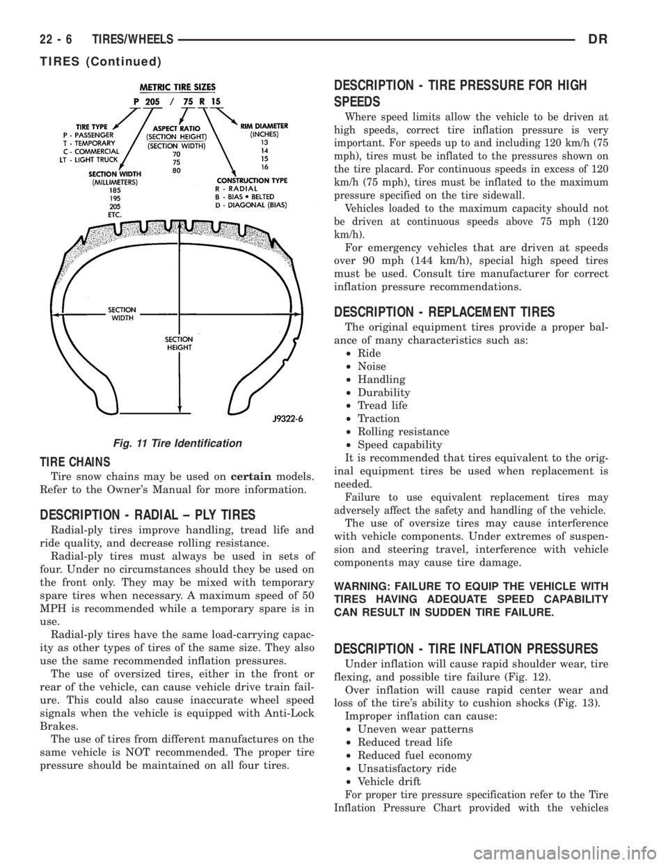
Fig. 11 Tire Identification
22 - 6 TIRES/WHEELSDR
TIRES (Continued)
Page 2580 of 2895
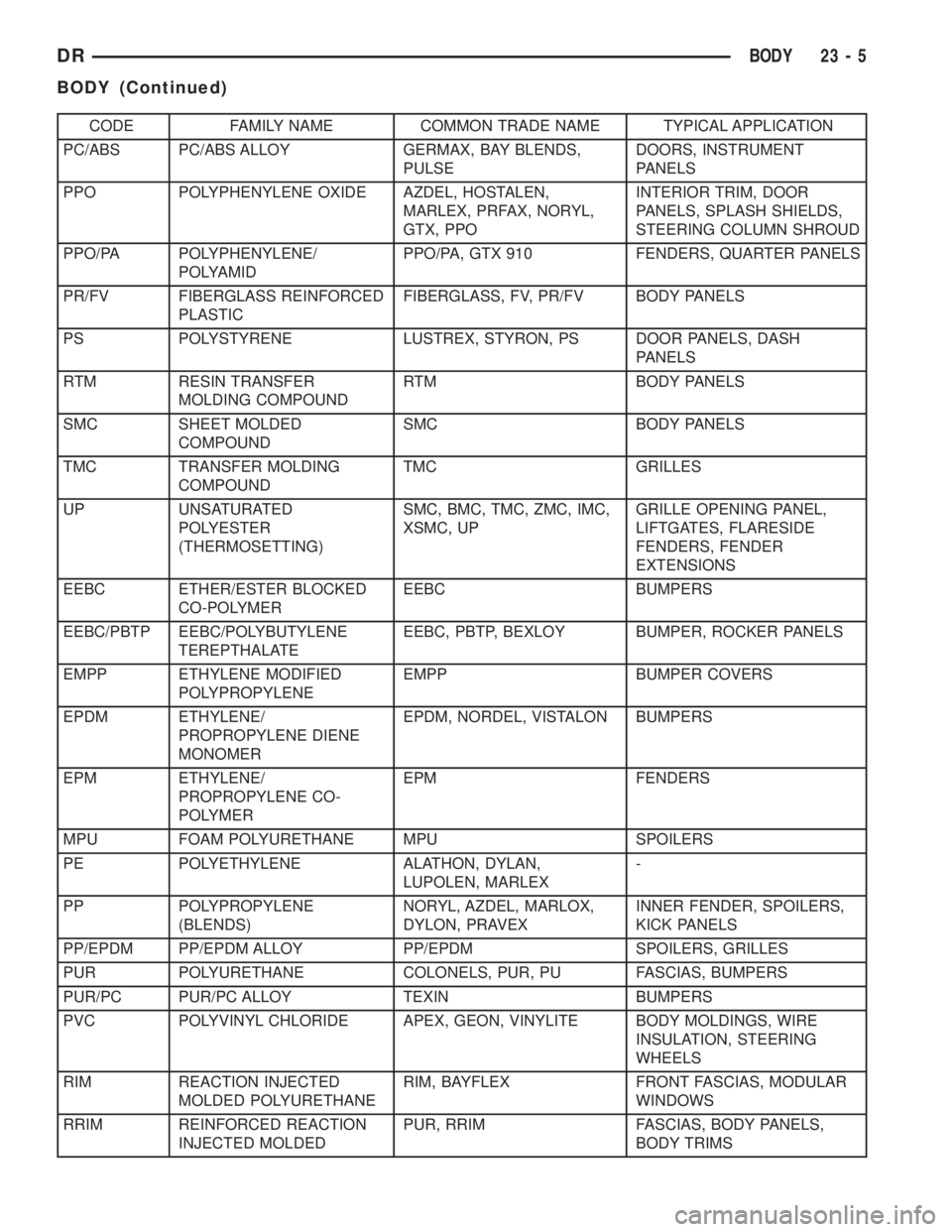
CODE FAMILY NAME COMMON TRADE NAME TYPICAL APPLICATION
PC/ABS PC/ABS ALLOY GERMAX, BAY BLENDS,
PULSEDOORS, INSTRUMENT
PANELS
PPO POLYPHENYLENE OXIDE AZDEL, HOSTALEN,
MARLEX, PRFAX, NORYL,
GTX, PPOINTERIOR TRIM, DOOR
PANELS, SPLASH SHIELDS,
STEERING COLUMN SHROUD
PPO/PA POLYPHENYLENE/
POLYAMIDPPO/PA, GTX 910 FENDERS, QUARTER PANELS
PR/FV FIBERGLASS REINFORCED
PLASTICFIBERGLASS, FV, PR/FV BODY PANELS
PS POLYSTYRENE LUSTREX, STYRON, PS DOOR PANELS, DASH
PANELS
RTM RESIN TRANSFER
MOLDING COMPOUNDRTM BODY PANELS
SMC SHEET MOLDED
COMPOUNDSMC BODY PANELS
TMC TRANSFER MOLDING
COMPOUNDTMC GRILLES
UP UNSATURATED
POLYESTER
(THERMOSETTING)SMC, BMC, TMC, ZMC, IMC,
XSMC, UPGRILLE OPENING PANEL,
LIFTGATES, FLARESIDE
FENDERS, FENDER
EXTENSIONS
EEBC ETHER/ESTER BLOCKED
CO-POLYMEREEBC BUMPERS
EEBC/PBTP EEBC/POLYBUTYLENE
TEREPTHALATEEEBC, PBTP, BEXLOY BUMPER, ROCKER PANELS
EMPP ETHYLENE MODIFIED
POLYPROPYLENEEMPP BUMPER COVERS
EPDM ETHYLENE/
PROPROPYLENE DIENE
MONOMEREPDM, NORDEL, VISTALON BUMPERS
EPM ETHYLENE/
PROPROPYLENE CO-
POLYMEREPM FENDERS
MPU FOAM POLYURETHANE MPU SPOILERS
PE POLYETHYLENE ALATHON, DYLAN,
LUPOLEN, MARLEX-
PP POLYPROPYLENE
(BLENDS)NORYL, AZDEL, MARLOX,
DYLON, PRAVEXINNER FENDER, SPOILERS,
KICK PANELS
PP/EPDM PP/EPDM ALLOY PP/EPDM SPOILERS, GRILLES
PUR POLYURETHANE COLONELS, PUR, PU FASCIAS, BUMPERS
PUR/PC PUR/PC ALLOY TEXIN BUMPERS
PVC POLYVINYL CHLORIDE APEX, GEON, VINYLITE BODY MOLDINGS, WIRE
INSULATION, STEERING
WHEELS
RIM REACTION INJECTED
MOLDED POLYURETHANERIM, BAYFLEX FRONT FASCIAS, MODULAR
WINDOWS
RRIM REINFORCED REACTION
INJECTED MOLDEDPUR, RRIM FASCIAS, BODY PANELS,
BODY TRIMS
DRBODY 23 - 5
BODY (Continued)
Page 2625 of 2895
INSTRUMENT PANEL
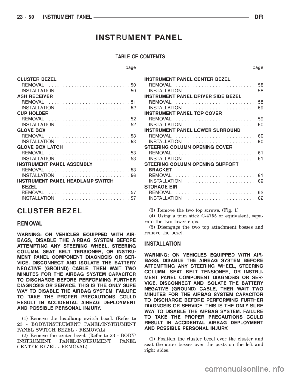
TABLE OF CONTENTS
page page
CLUSTER BEZEL
REMOVAL.............................50
INSTALLATION.........................50
ASH RECEIVER
REMOVAL.............................51
INSTALLATION.........................52
CUP HOLDER
REMOVAL.............................52
INSTALLATION.........................52
GLOVE BOX
REMOVAL.............................53
INSTALLATION.........................53
GLOVE BOX LATCH
REMOVAL.............................53
INSTALLATION.........................53
INSTRUMENT PANEL ASSEMBLY
REMOVAL.............................53
INSTALLATION.........................56
INSTRUMENT PANEL HEADLAMP SWITCH
BEZEL
REMOVAL.............................57
INSTALLATION.........................57INSTRUMENT PANEL CENTER BEZEL
REMOVAL.............................58
INSTALLATION.........................58
INSTRUMENT PANEL DRIVER SIDE BEZEL
REMOVAL.............................58
INSTALLATION.........................59
INSTRUMENT PANEL TOP COVER
REMOVAL.............................59
INSTALLATION.........................60
INSTRUMENT PANEL LOWER SURROUND
REMOVAL.............................60
INSTALLATION.........................60
STEERING COLUMN OPENING COVER
REMOVAL.............................61
INSTALLATION.........................61
STEERING COLUMN OPENING SUPPORT
BRACKET
REMOVAL.............................61
INSTALLATION.........................62
STORAGE BIN
REMOVAL.............................62
INSTALLATION.........................62
CLUSTER BEZEL
REMOVAL
WARNING: ON VEHICLES EQUIPPED WITH AIR-
BAGS, DISABLE THE AIRBAG SYSTEM BEFORE
ATTEMPTING ANY STEERING WHEEL, STEERING
COLUMN, SEAT BELT TENSIONER, OR INSTRU-
MENT PANEL COMPONENT DIAGNOSIS OR SER-
VICE. DISCONNECT AND ISOLATE THE BATTERY
NEGATIVE (GROUND) CABLE, THEN WAIT TWO
MINUTES FOR THE AIRBAG SYSTEM CAPACITOR
TO DISCHARGE BEFORE PERFORMING FURTHER
DIAGNOSIS OR SERVICE. THIS IS THE ONLY SURE
WAY TO DISABLE THE AIRBAG SYSTEM. FAILURE
TO TAKE THE PROPER PRECAUTIONS COULD
RESULT IN ACCIDENTAL AIRBAG DEPLOYMENT
AND POSSIBLE PERSONAL INJURY.
(1) Remove the headlamp switch bezel. (Refer to
23 - BODY/INSTRUMENT PANEL/INSTRUMENT
PANEL SWITCH BEZEL - REMOVAL)
(2) Remove the center bezel. (Refer to 23 - BODY/
INSTRUMENT PANEL/INSTRUMENT PANEL
CENTER BEZEL - REMOVAL)(3) Remove the two top screws. (Fig. 1)
(4) Using a trim stick C-4755 or equivalent, sepa-
rate the two lower clips.
(5) Disengage the two top attachment bosses and
remove the bezel.
INSTALLATION
WARNING: ON VEHICLES EQUIPPED WITH AIR-
BAGS, DISABLE THE AIRBAG SYSTEM BEFORE
ATTEMPTING ANY STEERING WHEEL, STEERING
COLUMN, SEAT BELT TENSIONER, OR INSTRU-
MENT PANEL COMPONENT DIAGNOSIS OR SER-
VICE. DISCONNECT AND ISOLATE THE BATTERY
NEGATIVE (GROUND) CABLE, THEN WAIT TWO
MINUTES FOR THE AIRBAG SYSTEM CAPACITOR
TO DISCHARGE BEFORE PERFORMING FURTHER
DIAGNOSIS OR SERVICE. THIS IS THE ONLY SURE
WAY TO DISABLE THE AIRBAG SYSTEM. FAILURE
TO TAKE THE PROPER PRECAUTIONS COULD
RESULT IN ACCIDENTAL AIRBAG DEPLOYMENT
AND POSSIBLE PERSONAL INJURY.
(1) Position the cluster bezel over the cluster and
seat the outer bosses over the posts on the left and
right sides.
23 - 50 INSTRUMENT PANELDR