2003 DODGE RAM steering wheel
[x] Cancel search: steering wheelPage 656 of 2895

REMOVAL
REMOVAL
WARNING: ON VEHICLES EQUIPPED WITH AIR-
BAGS, DISABLE THE SUPPLEMENTAL RESTRAINT
SYSTEM BEFORE ATTEMPTING ANY STEERING
WHEEL, STEERING COLUMN, DRIVER AIRBAG,
PASSENGER AIRBAG, SEAT BELT TENSIONER,
SIDE CURTAIN AIRBAG, OR INSTRUMENT PANEL
COMPONENT DIAGNOSIS OR SERVICE. DISCON-
NECT AND ISOLATE THE BATTERY NEGATIVE
(GROUND) CABLE, THEN WAIT TWO MINUTES FOR
THE SYSTEM CAPACITOR TO DISCHARGE BEFORE
PERFORMING FURTHER DIAGNOSIS OR SERVICE.
THIS IS THE ONLY SURE WAY TO DISABLE THE
SUPPLEMENTAL RESTRAINT SYSTEM. FAILURE TO
TAKE THE PROPER PRECAUTIONS COULD
RESULT IN ACCIDENTAL AIRBAG DEPLOYMENT
AND POSSIBLE PERSONAL INJURY.
WARNING: THE SIDE IMPACT AIRBAG CONTROL
MODULE CONTAINS THE IMPACT SENSOR, WHICH
ENABLES THE SYSTEM TO DEPLOY THE SIDE
CURTAIN AIRBAGS. NEVER STRIKE OR DROP THE
SIDE IMPACT AIRBAG CONTROL MODULE, AS IT
CAN DAMAGE THE IMPACT SENSOR OR AFFECT
ITS CALIBRATION. IF A SIDE IMPACT AIRBAG CON-
TROL MODULE IS ACCIDENTALLY DROPPED DUR-
ING SERVICE, THE MODULE MUST BE SCRAPPED
AND REPLACED WITH A NEW UNIT. FAILURE TO
OBSERVE THIS WARNING COULD RESULT IN ACCI-
DENTAL, INCOMPLETE, OR IMPROPER SIDE CUR-
TAIN AIRBAG DEPLOYMENT AND POSSIBLE
OCCUPANT INJURIES.
(1) Adjust the front seat to its most forward posi-
tion for easiest access to the lower B-pillar trim.
(2) Disconnect and isolate the battery negative
cable. Wait two minutes for the system capacitor to
discharge before further service.
(3) Remove the front outboard seat belt and retrac-
tor from the inside of the B-pillar. (Refer to 8 -
ELECTRICAL/RESTRAINTS/FRONT OUTBOARD
SEAT BELT & RETRACTOR - REMOVAL - STAN-
DARD CAB).
(4) Remove the four screws that secure the Side
Impact Airbag Control Module (SIACM) mounting
bracket to the inside of the B-pillar (Fig. 51).
(5) Reach through the retractor mounting hole in
the inner B-pillar to access and disengage the two
plastic push-in fasteners that secure the SIACM to
the inside of the B-pillar.(6) Pull the SIACM and mounting bracket out
through the retractor mounting hole far enough to
access and disconnect the body wire harness connec-
tor for the SIACM from the module connector recep-
tacle.
(7) Remove the SIACM and its mounting bracket
from the B-pillar as a unit.
REMOVAL
WARNING: ON VEHICLES EQUIPPED WITH AIR-
BAGS, DISABLE THE SUPPLEMENTAL RESTRAINT
SYSTEM BEFORE ATTEMPTING ANY STEERING
WHEEL, STEERING COLUMN, DRIVER AIRBAG,
PASSENGER AIRBAG, SEAT BELT TENSIONER,
SIDE CURTAIN AIRBAG, OR INSTRUMENT PANEL
COMPONENT DIAGNOSIS OR SERVICE. DISCON-
NECT AND ISOLATE THE BATTERY NEGATIVE
(GROUND) CABLE, THEN WAIT TWO MINUTES FOR
THE SYSTEM CAPACITOR TO DISCHARGE BEFORE
PERFORMING FURTHER DIAGNOSIS OR SERVICE.
THIS IS THE ONLY SURE WAY TO DISABLE THE
SUPPLEMENTAL RESTRAINT SYSTEM. FAILURE TO
TAKE THE PROPER PRECAUTIONS COULD
RESULT IN ACCIDENTAL AIRBAG DEPLOYMENT
AND POSSIBLE PERSONAL INJURY.
Fig. 51 Side Impact Airbag Control Module
Remove/Install - Std Cab
1 - B-PILLAR
2 - SCREW (4)
3 - FASTENER (2)
4 - BRACKET
5 - SIACM
6 - WIRE HARNESS CONNECTOR
DRRESTRAINTS 8O - 55
SIDE IMPACT AIRBAG CONTROL MODULE (Continued)
Page 657 of 2895

WARNING: THE SIDE IMPACT AIRBAG CONTROL
MODULE CONTAINS THE IMPACT SENSOR, WHICH
ENABLES THE SYSTEM TO DEPLOY THE SIDE
CURTAIN AIRBAGS. NEVER STRIKE OR DROP THE
SIDE IMPACT AIRBAG CONTROL MODULE, AS IT
CAN DAMAGE THE IMPACT SENSOR OR AFFECT
ITS CALIBRATION. IF A SIDE IMPACT AIRBAG CON-
TROL MODULE IS ACCIDENTALLY DROPPED DUR-
ING SERVICE, THE MODULE MUST BE SCRAPPED
AND REPLACED WITH A NEW UNIT. FAILURE TO
OBSERVE THIS WARNING COULD RESULT IN ACCI-
DENTAL, INCOMPLETE, OR IMPROPER SIDE CUR-
TAIN AIRBAG DEPLOYMENT AND POSSIBLE
OCCUPANT INJURIES.
(1) Adjust the front seat to its most forward posi-
tion for easiest access to the lower B-pillar trim.
(2) Disconnect and isolate the battery negative
cable. Wait two minutes for the system capacitor to
discharge before further service.
(3) Remove the front outboard seat belt and retrac-
tor from the inside of the B-pillar. (Refer to 8 -
ELECTRICAL/RESTRAINTS/FRONT OUTBOARD
SEAT BELT & RETRACTOR - REMOVAL - QUAD
CAB).
(4) Remove the four screws that secure the Side
Impact Airbag Control Module (SIACM) mounting
bracket to the inside of the B-pillar (Fig. 52).(5) Reach through the retractor mounting hole in
the inner B-pillar to access the SIACM and lift it
upward far enough to disengage the hook on the
mounting bracket from the slot on the inner B-pillar.
(6) Pull the SIACM and mounting bracket out
through the retractor mounting hole far enough to
access and disconnect the body wire harness connec-
tor for the SIACM from the module connector recep-
tacle.
(7) Remove the SIACM and its mounting bracket
from the B-pillar as a unit.
INSTALLATION
INSTALLATION
WARNING: ON VEHICLES EQUIPPED WITH AIR-
BAGS, DISABLE THE SUPPLEMENTAL RESTRAINT
SYSTEM BEFORE ATTEMPTING ANY STEERING
WHEEL, STEERING COLUMN, DRIVER AIRBAG,
PASSENGER AIRBAG, SEAT BELT TENSIONER,
SIDE CURTAIN AIRBAG, OR INSTRUMENT PANEL
COMPONENT DIAGNOSIS OR SERVICE. DISCON-
NECT AND ISOLATE THE BATTERY NEGATIVE
(GROUND) CABLE, THEN WAIT TWO MINUTES FOR
THE SYSTEM CAPACITOR TO DISCHARGE BEFORE
PERFORMING FURTHER DIAGNOSIS OR SERVICE.
THIS IS THE ONLY SURE WAY TO DISABLE THE
SUPPLEMENTAL RESTRAINT SYSTEM. FAILURE TO
TAKE THE PROPER PRECAUTIONS COULD
RESULT IN ACCIDENTAL AIRBAG DEPLOYMENT
AND POSSIBLE PERSONAL INJURY.
WARNING: THE SIDE IMPACT AIRBAG CONTROL
MODULE CONTAINS THE IMPACT SENSOR, WHICH
ENABLES THE SYSTEM TO DEPLOY THE SIDE
CURTAIN AIRBAGS. NEVER STRIKE OR DROP THE
SIDE IMPACT AIRBAG CONTROL MODULE, AS IT
CAN DAMAGE THE IMPACT SENSOR OR AFFECT
ITS CALIBRATION. IF A SIDE IMPACT AIRBAG CON-
TROL MODULE IS ACCIDENTALLY DROPPED DUR-
ING SERVICE, THE MODULE MUST BE SCRAPPED
AND REPLACED WITH A NEW UNIT. FAILURE TO
OBSERVE THIS WARNING COULD RESULT IN ACCI-
DENTAL, INCOMPLETE, OR IMPROPER SIDE CUR-
TAIN AIRBAG DEPLOYMENT AND POSSIBLE
OCCUPANT INJURIES.
(1) Position the Side Impact Airbag Control Mod-
ule (SIACM) and its mounting bracket to the B-pillar
as a unit (Fig. 51).
(2) Reconnect the body wire harness connector for
the SIACM to the module connector receptacle.
(3) Reach through the retractor mounting hole in
the inner B-pillar to position and engage the two
Fig. 52 Side Impact Airbag Control Module
Remove/Install - Quad Cab
1 - B-PILLAR
2 - WIRE HARNESS CONNECTOR
3 - SCREW (4)
4 - HOOK
5 - BRACKET
6 - SIACM
7 - SLOT
8O - 56 RESTRAINTSDR
SIDE IMPACT AIRBAG CONTROL MODULE (Continued)
Page 658 of 2895

plastic push-in fasteners that secure the SIACM to
the inside of the B-pillar.
(4) Loosely install the four screws that secure the
SIACM mounting bracket to the base of the B-pillar.
(5) Tighten the four screws that secure the SIACM
mounting bracket to the B-pillar in the following
sequence: upper left, lower right, lower left, upper
right. Tighten the screws to 12 N´m (105 in. lbs.).
(6) Reinstall the front outboard seat belt and
retractor to the inside of the B-pillar. (Refer to 8 -
ELECTRICAL/RESTRAINTS/FRONT OUTBOARD
SEAT BELT & RETRACTOR - INSTALLATION -
STANDARD CAB).
(7) Do not reconnect the battery negative cable at
this time. The supplemental restraint system verifi-
cation test procedure should be performed following
service of any supplemental restraint system compo-
nent. (Refer to 8 - ELECTRICAL/RESTRAINTS -
STANDARD PROCEDURE - VERIFICATION TEST).
INSTALLATION
WARNING: ON VEHICLES EQUIPPED WITH AIR-
BAGS, DISABLE THE SUPPLEMENTAL RESTRAINT
SYSTEM BEFORE ATTEMPTING ANY STEERING
WHEEL, STEERING COLUMN, DRIVER AIRBAG,
PASSENGER AIRBAG, SEAT BELT TENSIONER,
SIDE CURTAIN AIRBAG, OR INSTRUMENT PANEL
COMPONENT DIAGNOSIS OR SERVICE. DISCON-
NECT AND ISOLATE THE BATTERY NEGATIVE
(GROUND) CABLE, THEN WAIT TWO MINUTES FOR
THE SYSTEM CAPACITOR TO DISCHARGE BEFORE
PERFORMING FURTHER DIAGNOSIS OR SERVICE.
THIS IS THE ONLY SURE WAY TO DISABLE THE
SUPPLEMENTAL RESTRAINT SYSTEM. FAILURE TO
TAKE THE PROPER PRECAUTIONS COULD
RESULT IN ACCIDENTAL AIRBAG DEPLOYMENT
AND POSSIBLE PERSONAL INJURY.
WARNING: THE SIDE IMPACT AIRBAG CONTROL
MODULE CONTAINS THE IMPACT SENSOR, WHICHENABLES THE SYSTEM TO DEPLOY THE SIDE
CURTAIN AIRBAGS. NEVER STRIKE OR DROP THE
SIDE IMPACT AIRBAG CONTROL MODULE, AS IT
CAN DAMAGE THE IMPACT SENSOR OR AFFECT
ITS CALIBRATION. IF A SIDE IMPACT AIRBAG CON-
TROL MODULE IS ACCIDENTALLY DROPPED DUR-
ING SERVICE, THE MODULE MUST BE SCRAPPED
AND REPLACED WITH A NEW UNIT. FAILURE TO
OBSERVE THIS WARNING COULD RESULT IN ACCI-
DENTAL, INCOMPLETE, OR IMPROPER SIDE CUR-
TAIN AIRBAG DEPLOYMENT AND POSSIBLE
OCCUPANT INJURIES.
(1) Position the Side Impact Airbag Control Mod-
ule (SIACM) and its mounting bracket to the B-pillar
as a unit (Fig. 52).
(2) Reconnect the body wire harness connector for
the SIACM to the module connector receptacle.
(3) Reach through the retractor mounting hole in
the inner B-pillar to position and engage the hook on
the SIACM mounting bracket in the slot of the inner
B-pillar.
(4) Loosely install the four screws that secure the
SIACM mounting bracket to the inner B-pillar.
(5) Tighten the four screws that secure the SIACM
mounting bracket to the B-pillar in the following
sequence: upper left, lower right, lower left, upper
right. Tighten the screws to 12 N´m (105 in. lbs.).
(6) Reinstall the front outboard seat belt and
retractor to the inside of the B-pillar. (Refer to 8 -
ELECTRICAL/RESTRAINTS/FRONT OUTBOARD
SEAT BELT & RETRACTOR - INSTALLATION -
QUAD CAB).
(7) Do not reconnect the battery negative cable at
this time. The supplemental restraint system verifi-
cation test procedure should be performed following
service of any supplemental restraint system compo-
nent. (Refer to 8 - ELECTRICAL/RESTRAINTS -
STANDARD PROCEDURE - VERIFICATION TEST).
DRRESTRAINTS 8O - 57
SIDE IMPACT AIRBAG CONTROL MODULE (Continued)
Page 660 of 2895
SPEED CONTROL
TABLE OF CONTENTS
page page
SPEED CONTROL
DESCRIPTION..........................1
OPERATION............................2
DIAGNOSIS AND TESTING
DIAGNOSIS AND TESTING - VACUUM
SUPPLY TEST.........................2
DIAGNOSIS AND TESTING - ROAD TEST....3
SPECIFICATIONS
TORQUE - SPEED CONTROL.............3
CABLE
DESCRIPTION..........................3
OPERATION............................3
REMOVAL.............................3
INSTALLATION..........................6
SERVO
DESCRIPTION..........................6OPERATION............................7
REMOVAL.............................7
INSTALLATION..........................7
SWITCH
DESCRIPTION..........................8
OPERATION............................8
REMOVAL.............................9
INSTALLATION..........................9
VACUUM RESERVOIR
DESCRIPTION..........................9
OPERATION............................9
DIAGNOSIS AND TESTING - VACUUM
RESERVOIR..........................9
REMOVAL.............................10
INSTALLATION.........................10
SPEED CONTROL
DESCRIPTION
All 3.7L/4.7L/5.9L/8.0LGas Engines and/or Diesel
With Automatic Trans.
The speed control system is operated by the use of
a cable and a vacuum controlled servo. Electronic
control of the speed control system is integrated into
the Powertrain Control Module (PCM). The controls
consist of two steering wheel mounted switches. The
switches are labeled: ON/OFF, RES/ACCEL, SET,
COAST, and CANCEL.
The system is designed to operate at speeds above
30 mph (50 km/h).
WARNING: THE USE OF SPEED CONTROL IS NOT
RECOMMENDED WHEN DRIVING CONDITIONS DO
NOT PERMIT MAINTAINING A CONSTANT SPEED,
SUCH AS IN HEAVY TRAFFIC OR ON ROADS THAT
ARE WINDING, ICY, SNOW COVERED, OR SLIP-
PERY.
5.7L Gas
The speed control system is fully electronically con-
trolled by the Powertrain Control Module (PCM).A
cable and a vacuum controlled servo are not
used. This is a servo-less system.The controls
consist of two steering wheel mounted switches. Theswitches are labeled: ON/OFF, RES/ACCEL, SET,
COAST, and CANCEL.
The system is designed to operate at speeds above
30 mph (50 km/h).
WARNING: THE USE OF SPEED CONTROL IS NOT
RECOMMENDED WHEN DRIVING CONDITIONS DO
NOT PERMIT MAINTAINING A CONSTANT SPEED,
SUCH AS IN HEAVY TRAFFIC OR ON ROADS THAT
ARE WINDING, ICY, SNOW COVERED, OR SLIP-
PERY.
5.9L Diesel With Manual Trans.
The speed control system is fully electronically con-
trolled by the Engine Control Module (ECM).A
cable and a vacuum controlled servo are not
used if the vehicle is equipped with a manual
transmission and a diesel engine. This is a ser-
vo-less system.The controls consist of two steering
wheel mounted switches. The switches are labeled:
ON/OFF, RES/ACCEL, SET, COAST, and CANCEL.
The system is designed to operate at speeds above
30 mph (50 km/h).
WARNING: THE USE OF SPEED CONTROL IS NOT
RECOMMENDED WHEN DRIVING CONDITIONS DO
NOT PERMIT MAINTAINING A CONSTANT SPEED,
SUCH AS IN HEAVY TRAFFIC OR ON ROADS THAT
ARE WINDING, ICY, SNOW COVERED, OR SLIP-
PERY.
DRSPEED CONTROL 8P - 1
Page 667 of 2895
(8) Connect servo cable to throttle body. Refer to
servo Cable Removal/Installation.
(9) Install left-front wheel-well liner.
(10) Connect negative battery cable to battery
(connect both cables if diesel).
(11) Before starting engine, operate accelerator
pedal to check for any binding.
SWITCH
DESCRIPTION
Two separate switch pods operate the speed control
system. The steering-wheel-mounted switches use
multiplexed circuits to provide inputs to the PCM (to
the ECM for diesel) for ON, OFF, RESUME, ACCEL-
ERATE, SET, DECEL and CANCEL modes. Refer to
the owner's manual for more information on speed
control switch functions and setting procedures.
The individual switches cannot be repaired. If one
switch fails, the entire switch module must be
replaced.
Depending on engine control computer (JTEC
having a 3± plug connector or NGC having a 4±
plug connector), 2 types of switches are used.
Both types of switches are internally and exter-
nally different. The switch used with the NGC
system has an attached pigtail lead. The switch
used with the JTEC system does not have an
attached pigtail lead.
OPERATION
When speed control is selected by depressing the
ON, OFF switch, the PCM (ECM for diesel) allows a
set speed to be stored in its RAM for speed control.
To store a set speed, depress the SET switch while
the vehicle is moving at a speed between approxi-
mately 35 and 85 mph. In order for the speed control
to engage, the brakes cannot be applied, nor can the
gear selector be indicating the transmission is in
Park or Neutral.
The speed control can be disengaged manually by:
²Stepping on the brake pedal
²Depressing the OFF switch
²Depressing the CANCEL switch.
The speed control can be disengaged also by any of
the following conditions:
²An indication of Park or Neutral
²The VSS signal increases at a rate of 10 mph
per second (indicates that the co-efficient of friction
between the road surface and tires is extremely low)
²Depressing the clutch pedal.
²Excessive engine rpm (indicates that the trans-
mission may be in a low gear)
²The VSS signal decreases at a rate of 10 mph
per second (indicates that the vehicle may have
decelerated at an extremely high rate)
²If the actual speed is not within 20 mph of the
set speed
The previous disengagement conditions are pro-
grammed for added safety.
Once the speed control has been disengaged,
depressing the ACCEL switch restores the vehicle to
the target speed that was stored in the PCM's RAM
(ECM for diesel).
NOTE: Depressing the OFF switch will erase the set
speed stored in the PCM's RAM.
If, while the speed control is engaged, the driver
wishes to increase vehicle speed, the PCM (ECM for
diesel) is programmed for an acceleration feature.
With the ACCEL switch held closed, the vehicle
accelerates slowly to the desired speed. The new tar-
get speed is stored in the PCM's RAM when the
ACCEL switch is released. The PCM also has a9tap-
up9feature in which vehicle speed increases at a rate
of approximately 2 mph for each momentary switch
activation of the ACCEL switch.
The PCM also provides a means to decelerate with-
out disengaging speed control. To decelerate from an
existing recorded target speed, depress and hold the
COAST switch until the desired speed is reached.
Then release the switch. The ON, OFF switch oper-
ates two components: the PCM's ON, OFF input, and
the battery voltage to the brake switch.
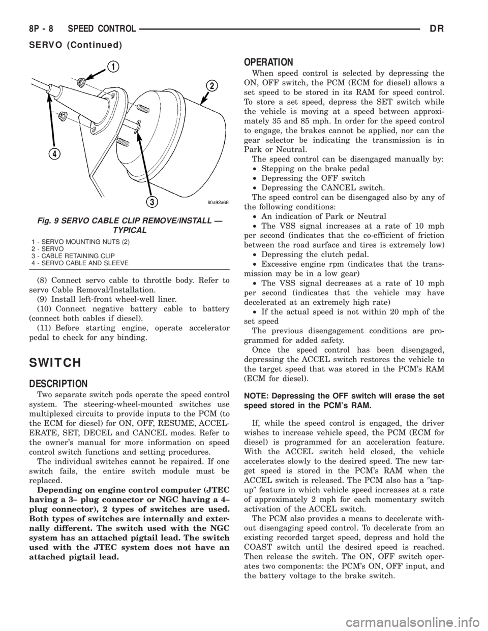
Fig. 9 SERVO CABLE CLIP REMOVE/INSTALL Ð
TYPICAL
1 - SERVO MOUNTING NUTS (2)
2 - SERVO
3 - CABLE RETAINING CLIP
4 - SERVO CABLE AND SLEEVE
8P - 8 SPEED CONTROLDR
SERVO (Continued)
Page 668 of 2895
REMOVAL
Depending on engine control computer (JTEC
having a 3±plug connector or 5.7L V-8 NGC hav-
ing a 4±plug connector), 2 types of switches are
used. Both types of switches are internally and
externally different. The switches used with the
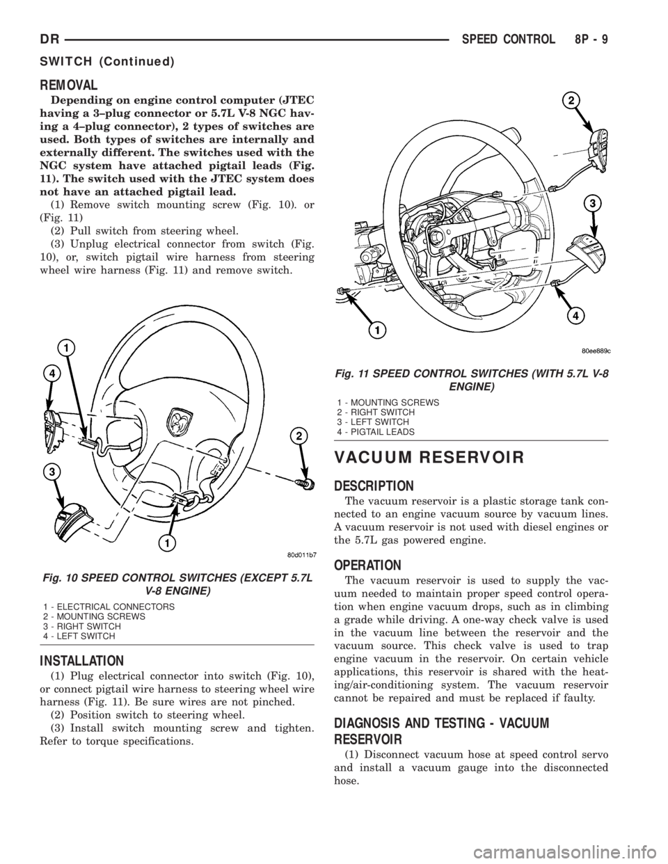
NGC system have attached pigtail leads (Fig.
11). The switch used with the JTEC system does
not have an attached pigtail lead.
(1) Remove switch mounting screw (Fig. 10). or
(Fig. 11)
(2) Pull switch from steering wheel.
(3) Unplug electrical connector from switch (Fig.
10), or, switch pigtail wire harness from steering
wheel wire harness (Fig. 11) and remove switch.
INSTALLATION
(1) Plug electrical connector into switch (Fig. 10),
or connect pigtail wire harness to steering wheel wire
harness (Fig. 11). Be sure wires are not pinched.
(2) Position switch to steering wheel.
(3) Install switch mounting screw and tighten.
Refer to torque specifications.
VACUUM RESERVOIR
DESCRIPTION
The vacuum reservoir is a plastic storage tank con-
nected to an engine vacuum source by vacuum lines.
A vacuum reservoir is not used with diesel engines or
the 5.7L gas powered engine.
OPERATION
The vacuum reservoir is used to supply the vac-
uum needed to maintain proper speed control opera-
tion when engine vacuum drops, such as in climbing
a grade while driving. A one-way check valve is used
in the vacuum line between the reservoir and the
vacuum source. This check valve is used to trap
engine vacuum in the reservoir. On certain vehicle
applications, this reservoir is shared with the heat-
ing/air-conditioning system. The vacuum reservoir
cannot be repaired and must be replaced if faulty.
DIAGNOSIS AND TESTING - VACUUM
RESERVOIR
(1) Disconnect vacuum hose at speed control servo
and install a vacuum gauge into the disconnected
hose.
Fig. 10 SPEED CONTROL SWITCHES (EXCEPT 5.7L
V-8 ENGINE)
1 - ELECTRICAL CONNECTORS
2 - MOUNTING SCREWS
3 - RIGHT SWITCH
4 - LEFT SWITCH
Fig. 11 SPEED CONTROL SWITCHES (WITH 5.7L V-8
ENGINE)
1 - MOUNTING SCREWS
2 - RIGHT SWITCH
3 - LEFT SWITCH
4 - PIGTAIL LEADS
DRSPEED CONTROL 8P - 9
SWITCH (Continued)
Page 672 of 2895
placed in its ªCustomer Learnº programming mode.
See Sentry Key Immobilizer System Transponder
Programming in this section for more information on
the ªCustomer Learnº programming mode.
For diagnosis or initialization of the SKIM and the
PCM, a DRBIIItscan tool and the proper Powertrain
Diagnostic Procedures manual are required. The
SKIM cannot be repaired and, if faulty or damaged,
the unit must be replaced.
DIAGNOSIS AND TESTING
VEHICLE THEFT SECURITY SYSTEM
WARNING: ON VEHICLES EQUIPPED WITH AIR-
BAGS, REFER TO RESTRAINT SYSTEMS BEFORE
ATTEMPTING ANY STEERING WHEEL, STEERING
COLUMN, OR INSTRUMENT PANEL COMPONENT
DIAGNOSIS OR SERVICE. FAILURE TO TAKE THE
PROPER PRECAUTIONS COULD RESULT IN ACCI-
DENTAL AIRBAG DEPLOYMENT AND POSSIBLE
PERSONAL INJURY.
NOTE: The most reliable, efficient, and accurate
means to diagnose the Vehicle Theft Security Sys-
tem (VTSS) and Sentry Key Immobilizer System
(SKIS) involves the use of a DRBlllTscan tool and
the proper Powertrain Diagnostic Procedures man-
ual.
The Vehicle Theft Security System (VTSS), Sentry
Key Immobilizer System (SKIS) and the Programma-
ble Communication Interface (PCI) bus network
should be diagnosed using a DRBIIItscan tool. The
DRBIIItwill allow confirmation that the PCI bus is
functional, that the Sentry Key Immobilizer Module
(SKIM) is placing the proper messages on the PCI
bus, and that the Powertrain Control Module (PCM)
and the Instrument Cluster are receiving the PCI
bus messages. Refer to the proper Powertrain or
Body Diagnostic Procedures manual.
Visually inspect the related wiring harness connec-
tors. Look for broken, bent, pushed out or corroded
terminals. If any of the conditions are present, repair
as necessary. Refer to Wiring Diagrams for complete
circuit descriptions and diagrams. Refer to (Refer to
8 - ELECTRICAL/ELECTRONIC CONTROL MOD-
ULES/SENTRY KEY IMMOBILIZER MODULE -
REMOVAL) for SKIM replacement.
STANDARD PROCEDURE
CONFIGURING A NEW MODULE / SWITCH
OPERATING MODES
To configure a new module or to switch operating
modes, a DRBIIItscan tool must be used.
(1) Hook up the DRBIIItscan tool to the Data
Link Connector (DLC).
(2) With the key in the ignition, turn the key to
the RUN position.
(3) After the DRBIIItscan tool initialization, per-
form the following:
(a) Select ªTheft Alarm.º
(b) Select ªVTSS.º
(c) Select ªMiscellaneous.º
(4) Once in the ªMiscellaneousº screen:
(a) If you wish to configure a new module, select
ªConfigure Module.º
(b) If you wish to put the module into customer
usage mode, select ªEnable VTSS.º
(c) If you wish to put the module into dealer lot
mode, select ªDealer Lot.º
SENTRY KEY IMMOBILIZER SYSTEM
INITIALIZATION
The Sentry Key Immobilizer System (SKIS) initial-
ization should be performed following a Sentry Key
Immobilizer Module (SKIM) replacement.
It can be summarized by the following:
(1) Obtain the vehicles unique PIN number
assigned to it's original SKIM from the vehicle
owner, the vehicle's invoice or from Chrysler's Cus-
tomer Center.
(2) With the DRBIIItscan tool, select ªTheft
Alarm,º ªSKIM,º Miscellaneous.º Select ªSKIM Mod-
ule Replacedº function and the DRBIIItwill prompt
you through the following steps.
(3) Enter secured access mode using the unique
four digit PIN number.
(4) Program the vehicle's VIN number into the
SKIM's memory.
(5) Program the country code into the SKIM's
memory (U.S.).
(6) Transfer the vehicle's unique Secret Key data
from the PCM. This process will require the SKIM to
be insecured access mode. The PIN number must
be entered into the DRBIIItbefore the SKIM will
entersecured access mode. Oncesecured access
modeis active, the SKIM will remain in that mode
for 60 seconds.
(7) Program all customer keys into the SKIM's
memory. This required that the SKIM be insecured
access modeThe SKIM will immediately exit
secured access modeafter each key is pro-
grammed.
DRVEHICLE THEFT SECURITY 8Q - 3
VEHICLE THEFT SECURITY (Continued)
Page 677 of 2895
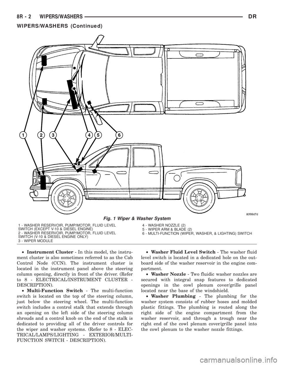
²Instrument Cluster- In this model, the instru-
ment cluster is also sometimes referred to as the Cab
Control Node (CCN). The instrument cluster is
located in the instrument panel above the steering
column opening, directly in front of the driver. (Refer
to 8 - ELECTRICAL/INSTRUMENT CLUSTER -
DESCRIPTION).
²Multi-Function Switch- The multi-function
switch is located on the top of the steering column,
just below the steering wheel. The multi-function
switch includes a control stalk that extends through
an opening on the left side of the steering column
shrouds and a control knob on the end of the stalk is
dedicated to providing all of the driver controls for
the wiper and washer systems. (Refer to 8 - ELEC-
TRICAL/LAMPS/LIGHTING - EXTERIOR/MULTI-
FUNCTION SWITCH - DESCRIPTION).²Washer Fluid Level Switch- The washer fluid
level switch is located in a dedicated hole on the out-
board side of the washer reservoir in the engine com-
partment.
²Washer Nozzle- Two fluidic washer nozzles are
secured with integral snap features to dedicated
openings in the cowl plenum cover/grille panel
located near the base of the windshield.
²Washer Plumbing- The plumbing for the
washer system consists of rubber hoses and molded
plastic fittings. The plumbing is routed along the
right side of the engine compartment from the
washer reservoir, and through a trough near the
right end of the cowl plenum cover/grille panel into
the cowl plenum to the washer nozzle fittings.
Fig. 1 Wiper & Washer System
1 - WASHER RESERVOIR, PUMP/MOTOR, FLUID LEVEL
SWITCH (EXCEPT V-10 & DIESEL ENGINE)
2 - WASHER RESERVOIR, PUMP/MOTOR, FLUID LEVEL
SWITCH (V-10 & DIESEL ENGINE ONLY)
3 - WIPER MODULE4 - WASHER NOZZLE (2)
5 - WIPER ARM & BLADE (2)
6 - MULTI-FUNCTION (WIPER, WASHER, & LIGHTING) SWITCH
8R - 2 WIPERS/WASHERSDR
WIPERS/WASHERS (Continued)