2003 DODGE RAM frame
[x] Cancel search: framePage 2653 of 2895
INSTALLATION
NOTE: Do not reuse the seat fasteners, always
replace with new ones.
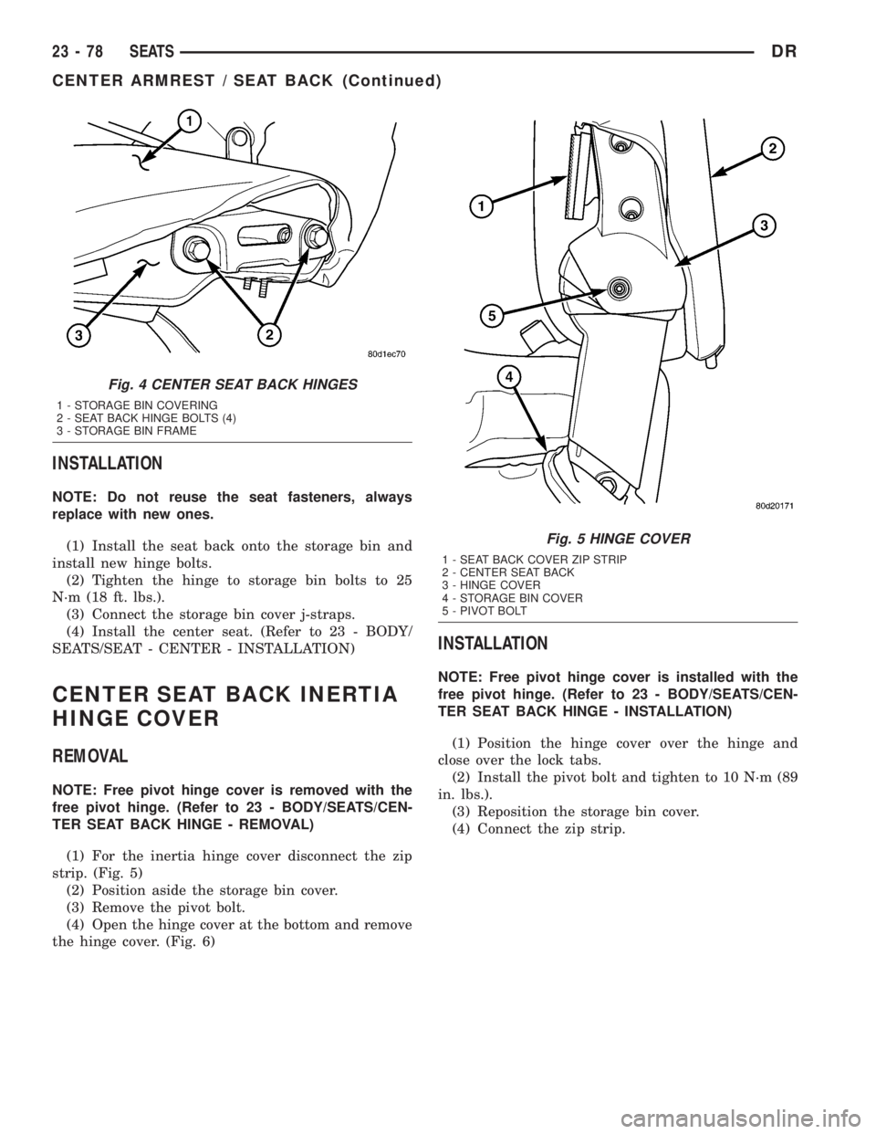
(1) Install the seat back onto the storage bin and
install new hinge bolts.
(2) Tighten the hinge to storage bin bolts to 25
N´m (18 ft. lbs.).
(3) Connect the storage bin cover j-straps.
(4) Install the center seat. (Refer to 23 - BODY/
SEATS/SEAT - CENTER - INSTALLATION)
CENTER SEAT BACK INERTIA
HINGE COVER
REMOVAL
NOTE: Free pivot hinge cover is removed with the
free pivot hinge. (Refer to 23 - BODY/SEATS/CEN-
TER SEAT BACK HINGE - REMOVAL)
(1) For the inertia hinge cover disconnect the zip
strip. (Fig. 5)
(2) Position aside the storage bin cover.
(3) Remove the pivot bolt.
(4) Open the hinge cover at the bottom and remove
the hinge cover. (Fig. 6)
INSTALLATION
NOTE: Free pivot hinge cover is installed with the
free pivot hinge. (Refer to 23 - BODY/SEATS/CEN-
TER SEAT BACK HINGE - INSTALLATION)
(1) Position the hinge cover over the hinge and
close over the lock tabs.
(2) Install the pivot bolt and tighten to 10 N´m (89
in. lbs.).
(3) Reposition the storage bin cover.
(4) Connect the zip strip.
Fig. 4 CENTER SEAT BACK HINGES
1 - STORAGE BIN COVERING
2 - SEAT BACK HINGE BOLTS (4)
3 - STORAGE BIN FRAME
Fig. 5 HINGE COVER
1 - SEAT BACK COVER ZIP STRIP
2 - CENTER SEAT BACK
3 - HINGE COVER
4 - STORAGE BIN COVER
5 - PIVOT BOLT
23 - 78 SEATSDR
CENTER ARMREST / SEAT BACK (Continued)
Page 2658 of 2895
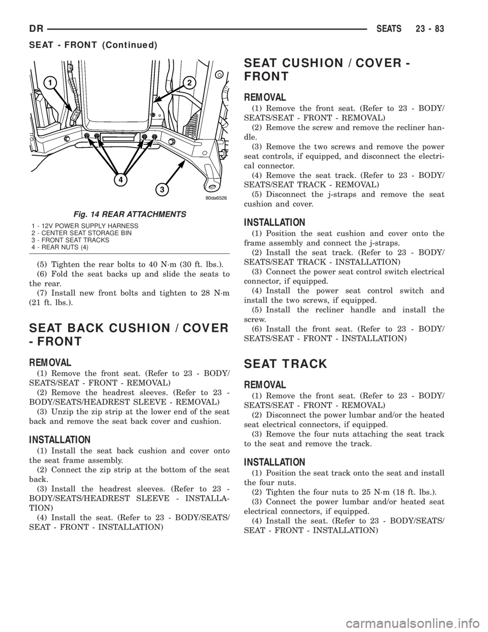
(5) Tighten the rear bolts to 40 N´m (30 ft. lbs.).
(6) Fold the seat backs up and slide the seats to
the rear.
(7) Install new front bolts and tighten to 28 N´m
(21 ft. lbs.).
SEAT BACK CUSHION / COVER
- FRONT
REMOVAL
(1) Remove the front seat. (Refer to 23 - BODY/
SEATS/SEAT - FRONT - REMOVAL)
(2) Remove the headrest sleeves. (Refer to 23 -
BODY/SEATS/HEADREST SLEEVE - REMOVAL)
(3) Unzip the zip strip at the lower end of the seat
back and remove the seat back cover and cushion.
INSTALLATION
(1) Install the seat back cushion and cover onto
the seat frame assembly.
(2) Connect the zip strip at the bottom of the seat
back.
(3) Install the headrest sleeves. (Refer to 23 -
BODY/SEATS/HEADREST SLEEVE - INSTALLA-
TION)
(4) Install the seat. (Refer to 23 - BODY/SEATS/
SEAT - FRONT - INSTALLATION)
SEAT CUSHION / COVER -
FRONT
REMOVAL
(1) Remove the front seat. (Refer to 23 - BODY/
SEATS/SEAT - FRONT - REMOVAL)
(2) Remove the screw and remove the recliner han-
dle.
(3) Remove the two screws and remove the power
seat controls, if equipped, and disconnect the electri-
cal connector.
(4) Remove the seat track. (Refer to 23 - BODY/
SEATS/SEAT TRACK - REMOVAL)
(5) Disconnect the j-straps and remove the seat
cushion and cover.
INSTALLATION
(1) Position the seat cushion and cover onto the
frame assembly and connect the j-straps.
(2) Install the seat track. (Refer to 23 - BODY/
SEATS/SEAT TRACK - INSTALLATION)
(3) Connect the power seat control switch electrical
connector, if equipped.
(4) Install the power seat control switch and
install the two screws, if equipped.
(5) Install the recliner handle and install the
screw.
(6) Install the front seat. (Refer to 23 - BODY/
SEATS/SEAT - FRONT - INSTALLATION)
SEAT TRACK
REMOVAL
(1) Remove the front seat. (Refer to 23 - BODY/
SEATS/SEAT - FRONT - REMOVAL)
(2) Disconnect the power lumbar and/or the heated
seat electrical connectors, if equipped.
(3) Remove the four nuts attaching the seat track
to the seat and remove the track.
INSTALLATION
(1) Position the seat track onto the seat and install
the four nuts.
(2) Tighten the four nuts to 25 N´m (18 ft. lbs.).
(3) Connect the power lumbar and/or heated seat
electrical connectors, if equipped.
(4) Install the seat. (Refer to 23 - BODY/SEATS/
SEAT - FRONT - INSTALLATION)
Fig. 14 REAR ATTACHMENTS
1 - 12V POWER SUPPLY HARNESS
2 - CENTER SEAT STORAGE BIN
3 - FRONT SEAT TRACKS
4 - REAR NUTS (4)
DRSEATS 23 - 83
SEAT - FRONT (Continued)
Page 2659 of 2895
SEAT - REAR
REMOVAL
(1) Remove the load floor. (Refer to 23 - BODY/IN-
TERIOR/LOAD FLOOR - REMOVAL)
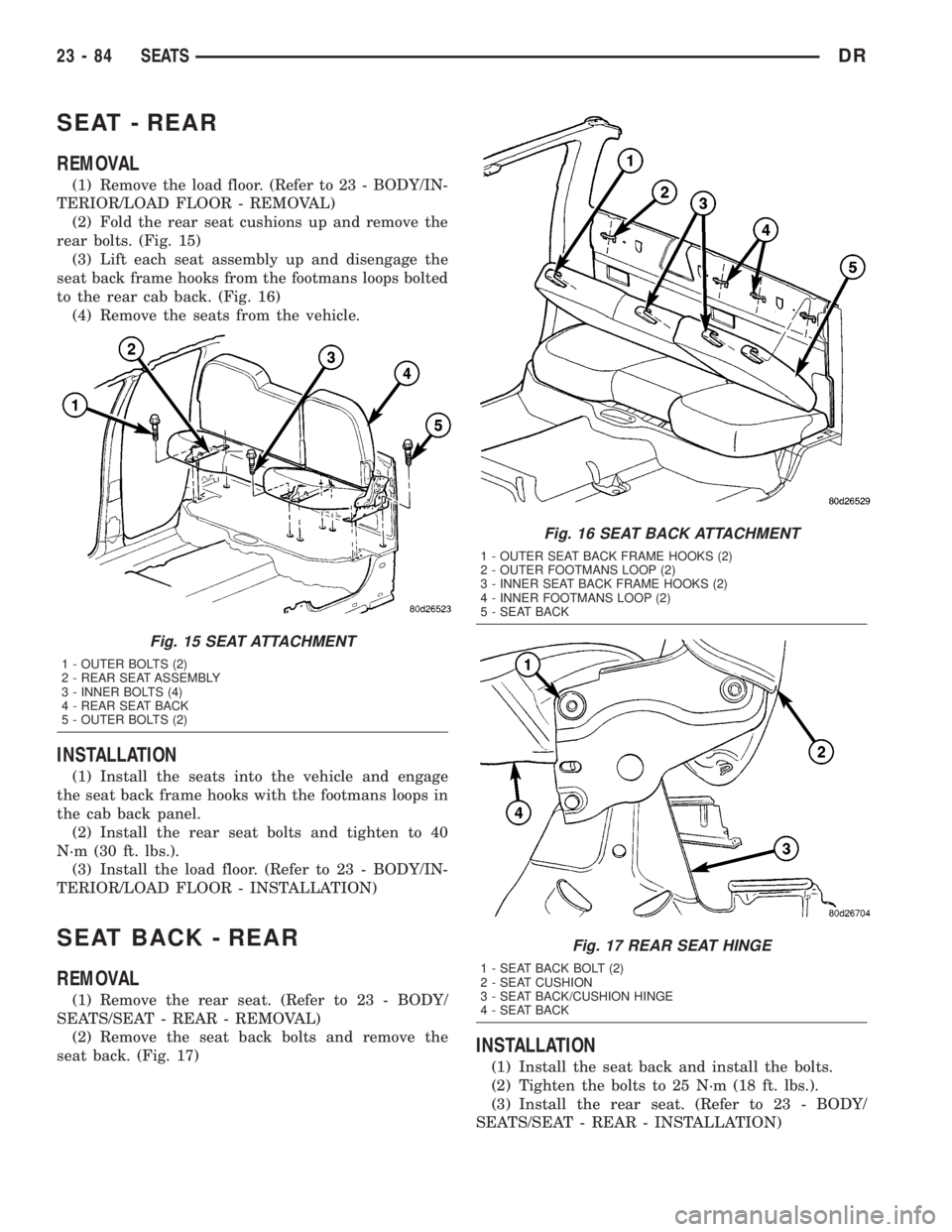
(2) Fold the rear seat cushions up and remove the
rear bolts. (Fig. 15)
(3) Lift each seat assembly up and disengage the
seat back frame hooks from the footmans loops bolted
to the rear cab back. (Fig. 16)
(4) Remove the seats from the vehicle.
INSTALLATION
(1) Install the seats into the vehicle and engage
the seat back frame hooks with the footmans loops in
the cab back panel.
(2) Install the rear seat bolts and tighten to 40
N´m (30 ft. lbs.).
(3) Install the load floor. (Refer to 23 - BODY/IN-
TERIOR/LOAD FLOOR - INSTALLATION)
SEAT BACK - REAR
REMOVAL
(1) Remove the rear seat. (Refer to 23 - BODY/
SEATS/SEAT - REAR - REMOVAL)
(2) Remove the seat back bolts and remove the
seat back. (Fig. 17)
INSTALLATION
(1) Install the seat back and install the bolts.
(2) Tighten the bolts to 25 N´m (18 ft. lbs.).
(3) Install the rear seat. (Refer to 23 - BODY/
SEATS/SEAT - REAR - INSTALLATION)
Fig. 15 SEAT ATTACHMENT
1 - OUTER BOLTS (2)
2 - REAR SEAT ASSEMBLY
3 - INNER BOLTS (4)
4 - REAR SEAT BACK
5 - OUTER BOLTS (2)
Fig. 16 SEAT BACK ATTACHMENT
1 - OUTER SEAT BACK FRAME HOOKS (2)
2 - OUTER FOOTMANS LOOP (2)
3 - INNER SEAT BACK FRAME HOOKS (2)
4 - INNER FOOTMANS LOOP (2)
5 - SEAT BACK
Fig. 17 REAR SEAT HINGE
1 - SEAT BACK BOLT (2)
2 - SEAT CUSHION
3 - SEAT BACK/CUSHION HINGE
4 - SEAT BACK
23 - 84 SEATSDR
Page 2660 of 2895
SEAT BACK CUSHION / COVER
- REAR
REMOVAL
(1) Remove the rear seat back. (Refer to 23 -
BODY/SEATS/SEAT BACK - REAR - REMOVAL)
(2) Unzip the zip strip at the bottom of the seat
back and remove the cover and cushion.
INSTALLATION
(1) Install the seat back cushion and cover and
connect the zip strip.
(2) Install the seat back. (Refer to 23 - BODY/
SEATS/SEAT BACK - REAR - INSTALLATION)
SEAT CUSHION / COVER -
REAR
REMOVAL
(1) Remove the rear seat. (Refer to 23 - BODY/
SEATS/SEAT - REAR - REMOVAL)
(2) Remove the screws and remove the grocery bag
hooks, if equipped.
(3) Separate the zip strip at the rear of the seat
cushion and remove the cushion and cover.
INSTALLATION
(1) Install the seat cushion and cover over the
cushion frame assembly and connect the zip strip.
(2) Install the grocery bag hooks and screws, if
equipped.
(3) Install the seat. (Refer to 23 - BODY/SEATS/
SEAT - REAR - INSTALLATION)
SEAT CUSHION FRAME - REAR
REMOVAL
(1) Remove the seat cushion/cover. (Refer to 23 -
BODY/SEATS/SEAT CUSHION / COVER - REAR -
REMOVAL)
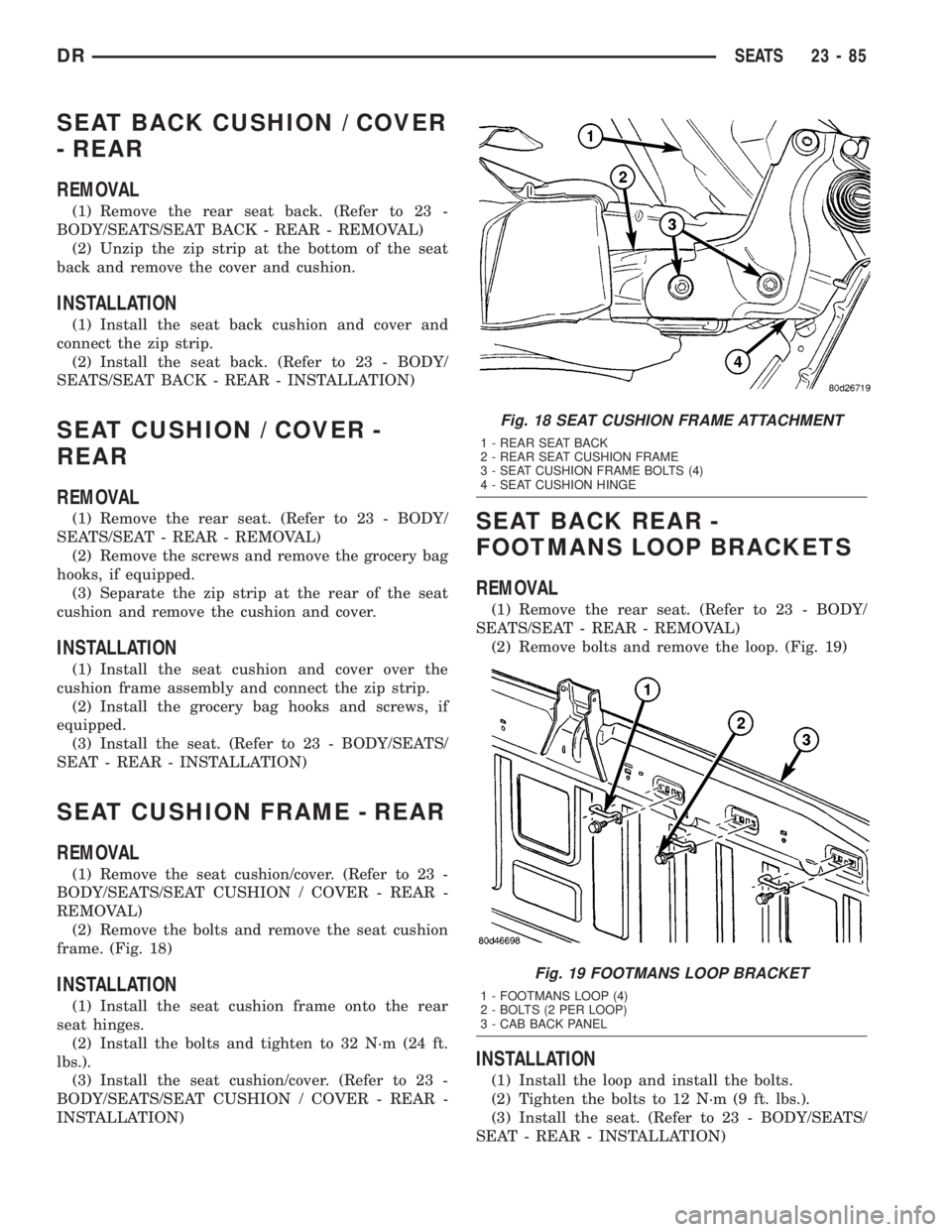
(2) Remove the bolts and remove the seat cushion
frame. (Fig. 18)
INSTALLATION
(1) Install the seat cushion frame onto the rear
seat hinges.
(2) Install the bolts and tighten to 32 N´m (24 ft.
lbs.).
(3) Install the seat cushion/cover. (Refer to 23 -
BODY/SEATS/SEAT CUSHION / COVER - REAR -
INSTALLATION)
SEAT BACK REAR -
FOOTMANS LOOP BRACKETS
REMOVAL
(1) Remove the rear seat. (Refer to 23 - BODY/
SEATS/SEAT - REAR - REMOVAL)
(2) Remove bolts and remove the loop. (Fig. 19)
INSTALLATION
(1) Install the loop and install the bolts.
(2) Tighten the bolts to 12 N´m (9 ft. lbs.).
(3) Install the seat. (Refer to 23 - BODY/SEATS/
SEAT - REAR - INSTALLATION)
Fig. 18 SEAT CUSHION FRAME ATTACHMENT
1 - REAR SEAT BACK
2 - REAR SEAT CUSHION FRAME
3 - SEAT CUSHION FRAME BOLTS (4)
4 - SEAT CUSHION HINGE
Fig. 19 FOOTMANS LOOP BRACKET
1 - FOOTMANS LOOP (4)
2 - BOLTS (2 PER LOOP)
3 - CAB BACK PANEL
DRSEATS 23 - 85
Page 2661 of 2895
STATIONARY GLASS
TABLE OF CONTENTS
page page
BACKLITE
REMOVAL.............................86
INSTALLATION.........................86
BACKLITE VENT GLASS
REMOVAL.............................87
INSTALLATION.........................87WINDSHIELD
WARNING
WINDSHIELD SAFETY PRECAUTIONS.....88
REMOVAL.............................88
INSTALLATION.........................88
BACKLITE
REMOVAL
It is difficult to salvage the backlite during the
removal operation. The backlite is part of the struc-
tural support for the roof. The urethane bonding
used to secure the glass to the fence is difficult to cut
or clean from any surface. Since the molding is set in
urethane, it is unlikely it would be salvaged. Before
removing the backlite, check the availability from the
parts supplier.
The backlite is attached to the window frame with
urethane adhesive. The urethane adhesive is applied
cold and seals the surface area between the window
opening and the glass. The primer adheres the ure-
thane adhesive to the backlite.
(1) Roll down door glass.
(2) Remove headliner. (Refer to 23 - BODY/INTE-
RIOR/HEADLINER - REMOVAL).
(3) On standard cab models remove the upper
b-pillar trim. (Refer to 23 - BODY/INTERIOR/B-PIL-
LAR UPPER TRIM - REMOVAL)
(4) On quad cab models remove the upper c-pillar
trim. (Refer to 23 - BODY/INTERIOR/C-PILLAR
UPPER TRIM - REMOVAL)
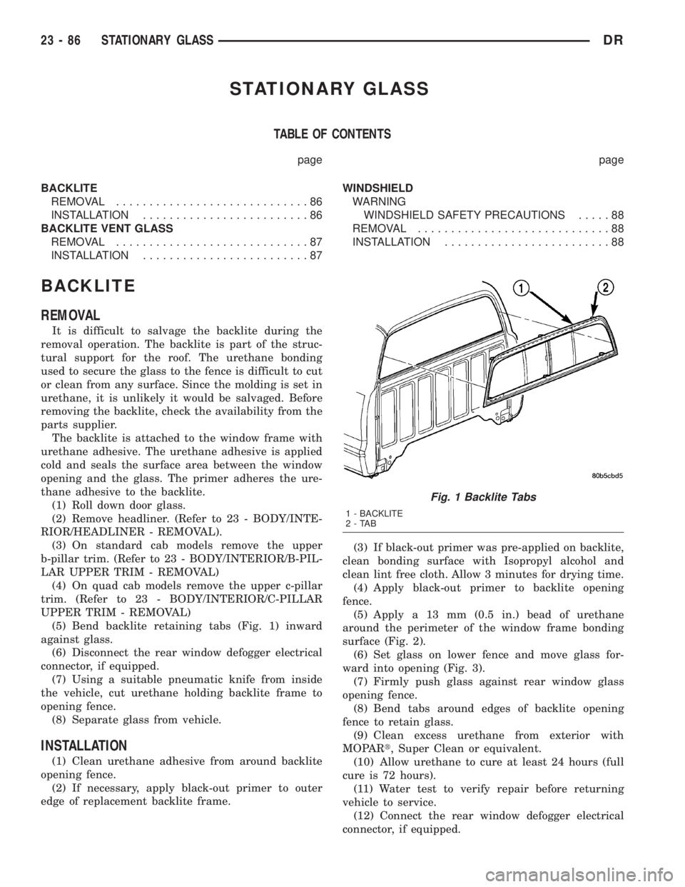
(5) Bend backlite retaining tabs (Fig. 1) inward
against glass.
(6) Disconnect the rear window defogger electrical
connector, if equipped.
(7) Using a suitable pneumatic knife from inside
the vehicle, cut urethane holding backlite frame to
opening fence.
(8) Separate glass from vehicle.
INSTALLATION
(1) Clean urethane adhesive from around backlite
opening fence.
(2) If necessary, apply black-out primer to outer
edge of replacement backlite frame.(3) If black-out primer was pre-applied on backlite,
clean bonding surface with Isopropyl alcohol and
clean lint free cloth. Allow 3 minutes for drying time.
(4) Apply black-out primer to backlite opening
fence.
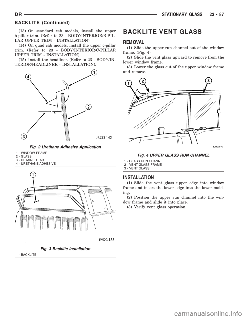
(5) Apply a 13 mm (0.5 in.) bead of urethane
around the perimeter of the window frame bonding
surface (Fig. 2).
(6) Set glass on lower fence and move glass for-
ward into opening (Fig. 3).
(7) Firmly push glass against rear window glass
opening fence.
(8) Bend tabs around edges of backlite opening
fence to retain glass.
(9) Clean excess urethane from exterior with
MOPARt, Super Clean or equivalent.
(10) Allow urethane to cure at least 24 hours (full
cure is 72 hours).
(11) Water test to verify repair before returning
vehicle to service.
(12) Connect the rear window defogger electrical
connector, if equipped.
Fig. 1 Backlite Tabs
1 - BACKLITE
2-TAB
23 - 86 STATIONARY GLASSDR
Page 2662 of 2895
(13) On standard cab models, install the upper
b-pillar trim. (Refer to 23 - BODY/INTERIOR/B-PIL-
LAR UPPER TRIM - INSTALLATION)
(14) On quad cab models, install the upper c-pillar
trim. (Refer to 23 - BODY/INTERIOR/C-PILLAR
UPPER TRIM - INSTALLATION)
(15) Install the headliner. (Refer to 23 - BODY/IN-
TERIOR/HEADLINER - INSTALLATION).BACKLITE VENT GLASS
REMOVAL
(1) Slide the upper run channel out of the window
frame. (Fig. 4)
(2) Slide the vent glass upward to remove from the
lower window frame.
(3) Lower the glass out of the upper window frame
and remove.
INSTALLATION
(1) Slide the vent glass upper edge into window
frame and insert the lower edge into the lower mold-
ing.
(2) Position the upper run channel into the win-
dow frame and slide it into place.
(3) Verify vent glass operation.
Fig. 2 Urethane Adhesive Application
1 - WINDOW FRAME
2 - GLASS
3 - RETAINER TAB
4 - URETHANE ADHESIVE
Fig. 3 Backlite Installation
1 - BACKLITE
Fig. 4 UPPER GLASS RUN CHANNEL
1 - GLASS RUN CHANNEL
2 - VENT GLASS FRAME
3 - VENT GLASS
DRSTATIONARY GLASS 23 - 87
BACKLITE (Continued)
Page 2667 of 2895
DOOR OPENING SEAL
REMOVAL
FRONT DOOR SEAL
(1) Remove the cowl trim panel. (Refer to 23 -
BODY/INTERIOR/COWL TRIM - REMOVAL)
(2) Remove the lower b-pillar trim panel. (Refer to
23 - BODY/INTERIOR/B-PILLAR LOWER TRIM -
REMOVAL)
(3) Separate the door opening seal from the door
opening flange. (Fig. 1)
REAR DOOR SEAL
(1) Remove the lower b-pillar trim panel. (Refer to
23 - BODY/INTERIOR/B-PILLAR LOWER TRIM -
REMOVAL)
(2) Remove the lower c-pillar trim. (Refer to 23 -
BODY/INTERIOR/C-PILLAR TRIM - REMOVAL)
(3) Separate the door opening seal from the door
opening flange. (Fig. 1)
INSTALLATION
FRONT DOOR SEAL
(1) Position the seal to the bottom of the door
opening, with bulb facing outboard, starting the
installation at the center of the lower flange. Press
the seal onto the sill flange and work around the
perimeter of the door opening until fully seated.
Work in one direction, smoothing the seal to avoid
puckers or wrinkles.
(2) Install the lower b-pillar trim. (Refer to 23 -
BODY/INTERIOR/B-PILLAR LOWER TRIM -
INSTALLATION)
(3) Install the cowl trim panel. (Refer to 23 -
BODY/INTERIOR/COWL TRIM - INSTALLATION)
(4) When installing a new weatherstrip on the
front door opening, remove the tear strip starting at
the splice and moving around the front of the door to
the back of the opening.
REAR DOOR SEAL
(1) Position the seal to the bottom of the door
opening, with bulb facing outboard, starting the
installation at the center of the lower flange. Press
the seal onto the sill flange and work around the
perimeter of the door opening until fully seated.
Work in one direction, smoothing the seal to avoid
puckers or wrinkles.
(2) Install the lower c-pillar trim. (Refer to 23 -
BODY/INTERIOR/C-PILLAR TRIM - INSTALLA-
TION)(3) Install the lower b-pillar trim. (Refer to 23 -
BODY/INTERIOR/B-PILLAR LOWER TRIM -
INSTALLATION)
(4) When installing a new weatherstrip on the rear
door opening, remove the tear strip starting at the
splice and moving around the back of the door to the
front of the opening.
DRIP RAIL WEATHERSTRIP
RETAINER
REMOVAL
(1) Separate the drip rail weatherstrip from the
weatherstrip retainer. (Fig. 1)
(2) Remove the seven screws and remove the
retainer.
INSTALLATION
(1) Install the weatherstrip retainer and install
the seven screws.
(2) Position the weatherstrip over the retainer
flange and seat fully.
FRONT DOOR GLASS RUN
WEATHERSTRIP
REMOVAL
(1) Remove the door glass. (Refer to 23 - BODY/
DOOR - FRONT/DOOR GLASS - REMOVAL)
(2) Separate the weatherstrip out of the door
frame and remove through the window opening. (Fig.
2)
INSTALLATION
NOTE: A mixture of soap and water may be used to
aid installation of the weatherstrip into the corners.
(1) Position the glass run weatherstrip into the
door through the window opening.
(2) Position the weatherstrip into the upper cor-
ners and seat firmly.
(3) From back to front, seat the weatherstrip
between the corners and then down the sides firmly
(4) Install the door glass. (Refer to 23 - BODY/
DOOR - FRONT/DOOR GLASS - INSTALLATION)
23 - 92 WEATHERSTRIP/SEALSDR
Page 2668 of 2895
FRONT DOOR OUTER BELT
MOLDING
REMOVAL
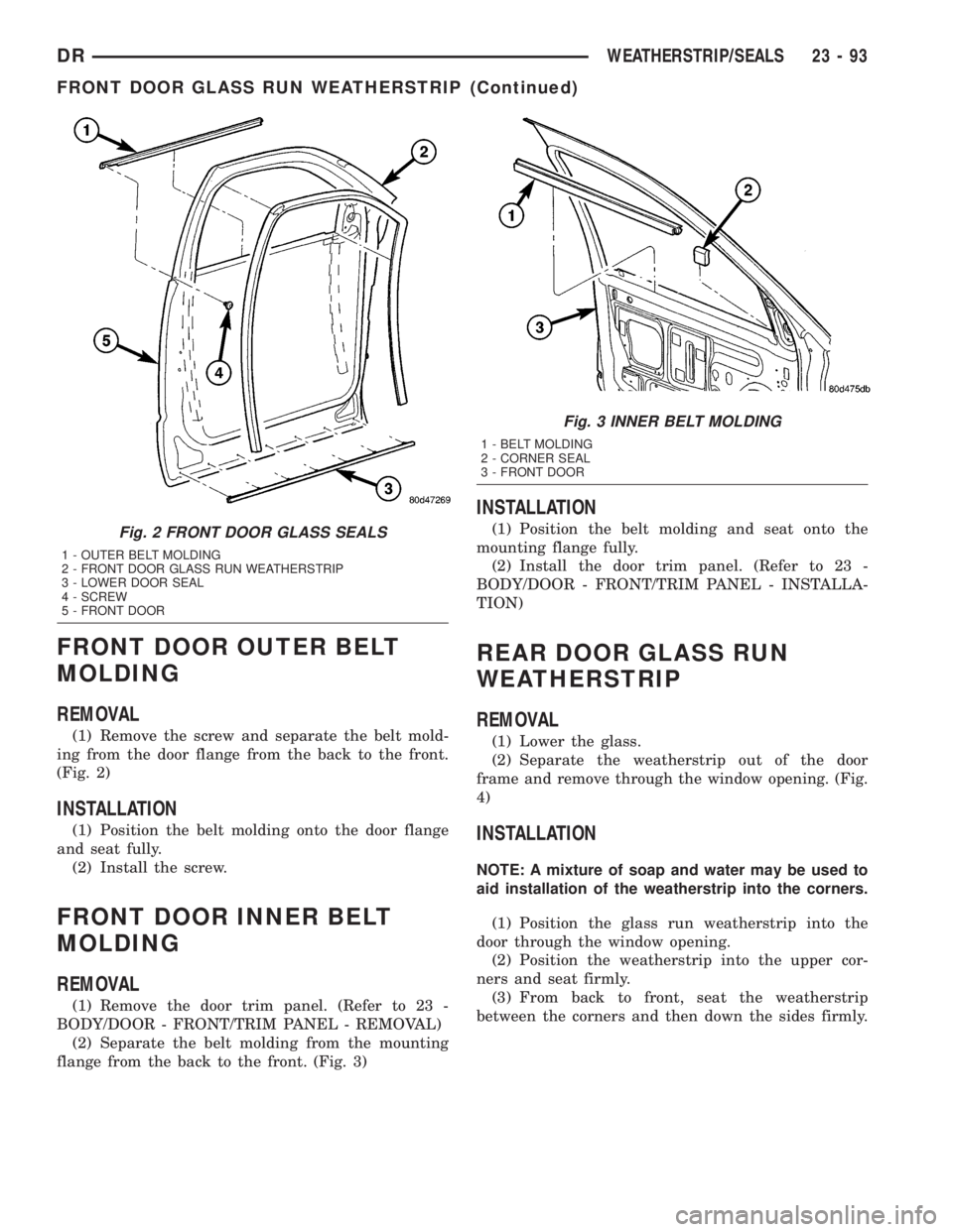
(1) Remove the screw and separate the belt mold-
ing from the door flange from the back to the front.
(Fig. 2)
INSTALLATION
(1) Position the belt molding onto the door flange
and seat fully.
(2) Install the screw.
FRONT DOOR INNER BELT
MOLDING
REMOVAL
(1) Remove the door trim panel. (Refer to 23 -
BODY/DOOR - FRONT/TRIM PANEL - REMOVAL)
(2) Separate the belt molding from the mounting
flange from the back to the front. (Fig. 3)
INSTALLATION
(1) Position the belt molding and seat onto the
mounting flange fully.
(2) Install the door trim panel. (Refer to 23 -
BODY/DOOR - FRONT/TRIM PANEL - INSTALLA-
TION)
REAR DOOR GLASS RUN
WEATHERSTRIP
REMOVAL
(1) Lower the glass.
(2) Separate the weatherstrip out of the door
frame and remove through the window opening. (Fig.
4)
INSTALLATION
NOTE: A mixture of soap and water may be used to
aid installation of the weatherstrip into the corners.
(1) Position the glass run weatherstrip into the
door through the window opening.
(2) Position the weatherstrip into the upper cor-
ners and seat firmly.
(3) From back to front, seat the weatherstrip
between the corners and then down the sides firmly.
Fig. 2 FRONT DOOR GLASS SEALS
1 - OUTER BELT MOLDING
2 - FRONT DOOR GLASS RUN WEATHERSTRIP
3 - LOWER DOOR SEAL
4 - SCREW
5 - FRONT DOOR
Fig. 3 INNER BELT MOLDING
1 - BELT MOLDING
2 - CORNER SEAL
3 - FRONT DOOR
DRWEATHERSTRIP/SEALS 23 - 93
FRONT DOOR GLASS RUN WEATHERSTRIP (Continued)