2003 DODGE RAM frame
[x] Cancel search: framePage 1810 of 2895
INSTALLATION
NOTE: Before installing gear inspect bushings and
replace if worn or damaged.
NOTE: In the frame there is two holes for the
mounting of the steering gear one is slotted and
one is round, When tightening the gear to specifi-
cations make sure to tighten the mounting bolt with
the hole first to avoided movement of the steering
gear.
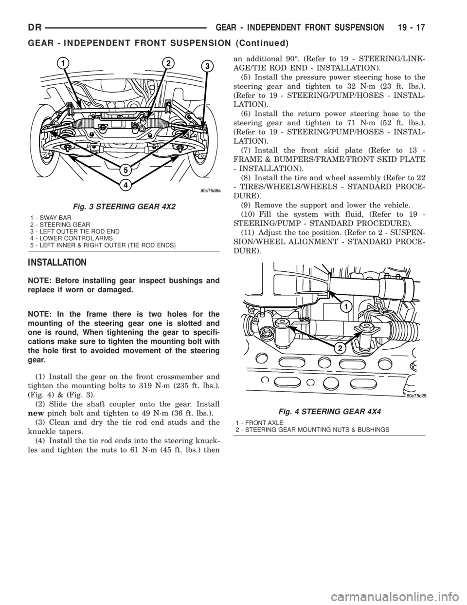
(1) Install the gear on the front crossmember and
tighten the mounting bolts to 319 N´m (235 ft. lbs.).
(Fig. 4) & (Fig. 3).
(2) Slide the shaft coupler onto the gear. Install
newpinch bolt and tighten to 49 N´m (36 ft. lbs.).
(3) Clean and dry the tie rod end studs and the
knuckle tapers.
(4) Install the tie rod ends into the steering knuck-
les and tighten the nuts to 61 N´m (45 ft. lbs.) thenan additional 90É. (Refer to 19 - STEERING/LINK-
AGE/TIE ROD END - INSTALLATION).
(5) Install the pressure power steering hose to the
steering gear and tighten to 32 N´m (23 ft. lbs.).
(Refer to 19 - STEERING/PUMP/HOSES - INSTAL-
LATION).
(6) Install the return power steering hose to the
steering gear and tighten to 71 N´m (52 ft. lbs.).
(Refer to 19 - STEERING/PUMP/HOSES - INSTAL-
LATION).
(7) Install the front skid plate (Refer to 13 -
FRAME & BUMPERS/FRAME/FRONT SKID PLATE
- INSTALLATION).
(8) Install the tire and wheel assembly (Refer to 22
- TIRES/WHEELS/WHEELS - STANDARD PROCE-
DURE).
(9) Remove the support and lower the vehicle.
(10) Fill the system with fluid, (Refer to 19 -
STEERING/PUMP - STANDARD PROCEDURE).
(11) Adjust the toe position. (Refer to 2 - SUSPEN-
SION/WHEEL ALIGNMENT - STANDARD PROCE-
DURE).
Fig. 3 STEERING GEAR 4X2
1-SWAYBAR
2 - STEERING GEAR
3 - LEFT OUTER TIE ROD END
4 - LOWER CONTROL ARMS
5 - LEFT INNER & RIGHT OUTER (TIE ROD ENDS)
Fig. 4 STEERING GEAR 4X4
1 - FRONT AXLE
2 - STEERING GEAR MOUNTING NUTS & BUSHINGS
DRGEAR - INDEPENDENT FRONT SUSPENSION 19 - 17
GEAR - INDEPENDENT FRONT SUSPENSION (Continued)
Page 1811 of 2895
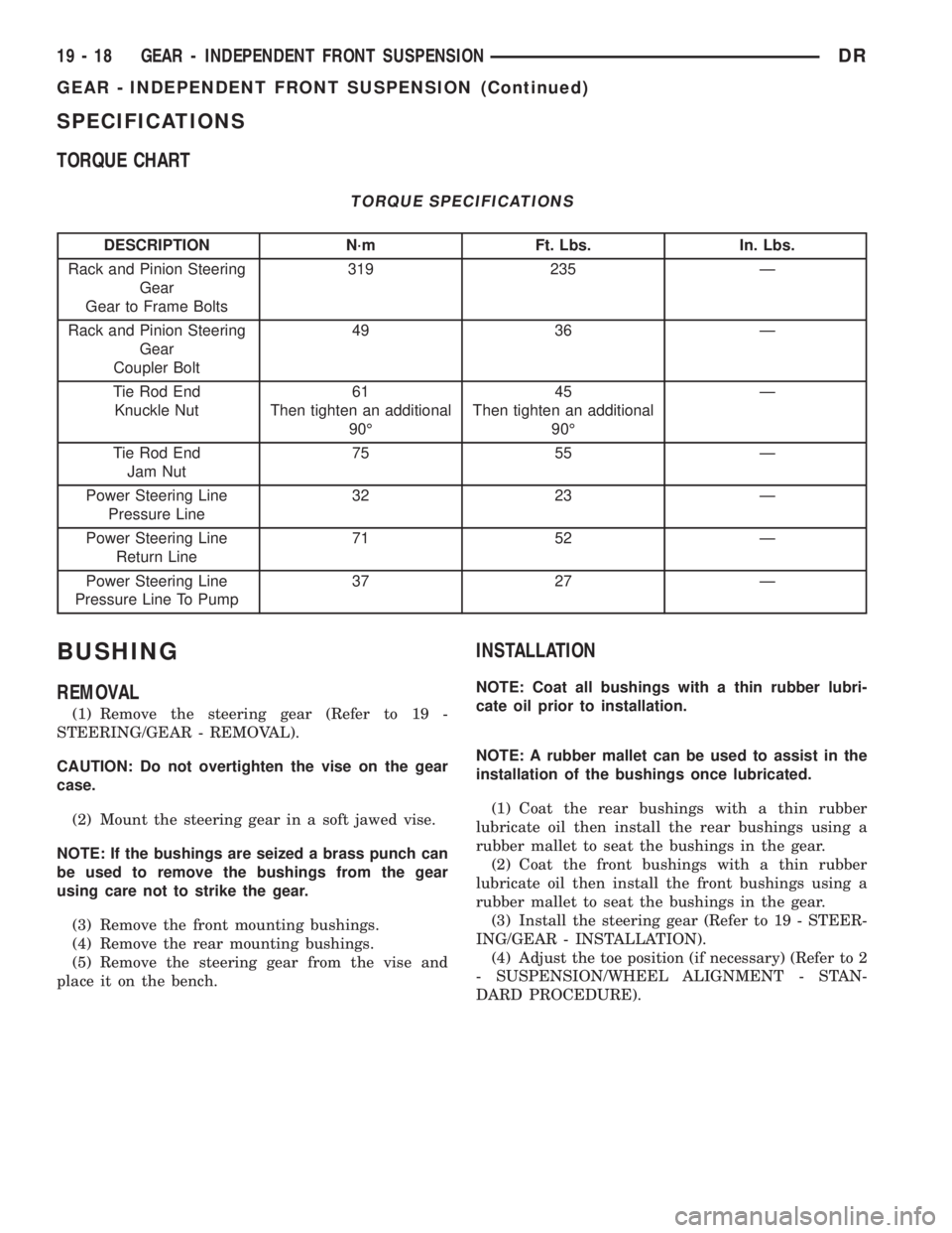
SPECIFICATIONS
TORQUE CHART
TORQUE SPECIFICATIONS
DESCRIPTION N´m Ft. Lbs. In. Lbs.
Rack and Pinion Steering
Gear
Gear to Frame Bolts319 235 Ð
Rack and Pinion Steering
Gear
Coupler Bolt49 36 Ð
Tie Rod End
Knuckle Nut61
Then tighten an additional
90É45
Then tighten an additional
90ÉÐ
Tie Rod End
Jam Nut75 55 Ð
Power Steering Line
Pressure Line32 23 Ð
Power Steering Line
Return Line71 52 Ð
Power Steering Line
Pressure Line To Pump37 27 Ð
BUSHING
REMOVAL
(1) Remove the steering gear (Refer to 19 -
STEERING/GEAR - REMOVAL).
CAUTION: Do not overtighten the vise on the gear
case.
(2) Mount the steering gear in a soft jawed vise.
NOTE: If the bushings are seized a brass punch can
be used to remove the bushings from the gear
using care not to strike the gear.
(3) Remove the front mounting bushings.
(4) Remove the rear mounting bushings.
(5) Remove the steering gear from the vise and
place it on the bench.
INSTALLATION
NOTE: Coat all bushings with a thin rubber lubri-
cate oil prior to installation.
NOTE: A rubber mallet can be used to assist in the
installation of the bushings once lubricated.
(1) Coat the rear bushings with a thin rubber
lubricate oil then install the rear bushings using a
rubber mallet to seat the bushings in the gear.
(2) Coat the front bushings with a thin rubber
lubricate oil then install the front bushings using a
rubber mallet to seat the bushings in the gear.
(3) Install the steering gear (Refer to 19 - STEER-
ING/GEAR - INSTALLATION).
(4) Adjust the toe position (if necessary) (Refer to 2
- SUSPENSION/WHEEL ALIGNMENT - STAN-
DARD PROCEDURE).
19 - 18 GEAR - INDEPENDENT FRONT SUSPENSIONDR
GEAR - INDEPENDENT FRONT SUSPENSION (Continued)
Page 1813 of 2895
(4) Disconnect and cap the fluid hoses from steer-
ing gear (Refer to 19 - STEERING/PUMP/HOSES -
REMOVAL).
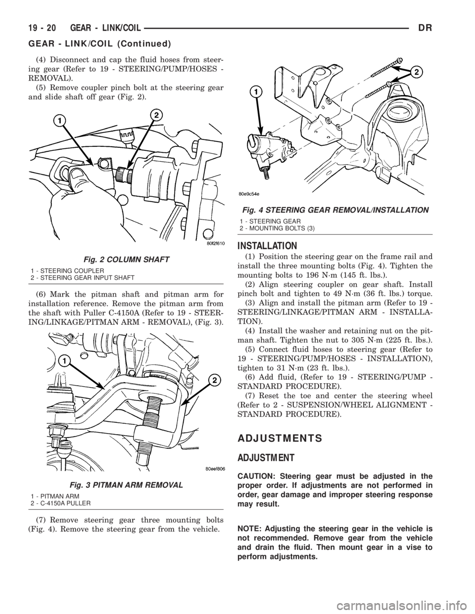
(5) Remove coupler pinch bolt at the steering gear
and slide shaft off gear (Fig. 2).
(6) Mark the pitman shaft and pitman arm for
installation reference. Remove the pitman arm from
the shaft with Puller C-4150A (Refer to 19 - STEER-
ING/LINKAGE/PITMAN ARM - REMOVAL), (Fig. 3).
(7) Remove steering gear three mounting bolts
(Fig. 4). Remove the steering gear from the vehicle.
INSTALLATION
(1) Position the steering gear on the frame rail and
install the three mounting bolts (Fig. 4). Tighten the
mounting bolts to 196 N´m (145 ft. lbs.).
(2) Align steering coupler on gear shaft. Install
pinch bolt and tighten to 49 N´m (36 ft. lbs.) torque.
(3) Align and install the pitman arm (Refer to 19 -
STEERING/LINKAGE/PITMAN ARM - INSTALLA-
TION).
(4) Install the washer and retaining nut on the pit-
man shaft. Tighten the nut to 305 N´m (225 ft. lbs.).
(5) Connect fluid hoses to steering gear (Refer to
19 - STEERING/PUMP/HOSES - INSTALLATION),
tighten to 31 N´m (23 ft. lbs.).
(6) Add fluid, (Refer to 19 - STEERING/PUMP -
STANDARD PROCEDURE).
(7) Reset the toe and center the steering wheel
(Refer to 2 - SUSPENSION/WHEEL ALIGNMENT -
STANDARD PROCEDURE).
ADJUSTMENTS
ADJUSTMENT
CAUTION: Steering gear must be adjusted in the
proper order. If adjustments are not performed in
order, gear damage and improper steering response
may result.
NOTE: Adjusting the steering gear in the vehicle is
not recommended. Remove gear from the vehicle
and drain the fluid. Then mount gear in a vise to
perform adjustments.
Fig. 2 COLUMN SHAFT
1 - STEERING COUPLER
2 - STEERING GEAR INPUT SHAFT
Fig. 3 PITMAN ARM REMOVAL
1 - PITMAN ARM
2 - C-4150A PULLER
Fig. 4 STEERING GEAR REMOVAL/INSTALLATION
1 - STEERING GEAR
2 - MOUNTING BOLTS (3)
19 - 20 GEAR - LINK/COILDR
GEAR - LINK/COIL (Continued)
Page 1815 of 2895
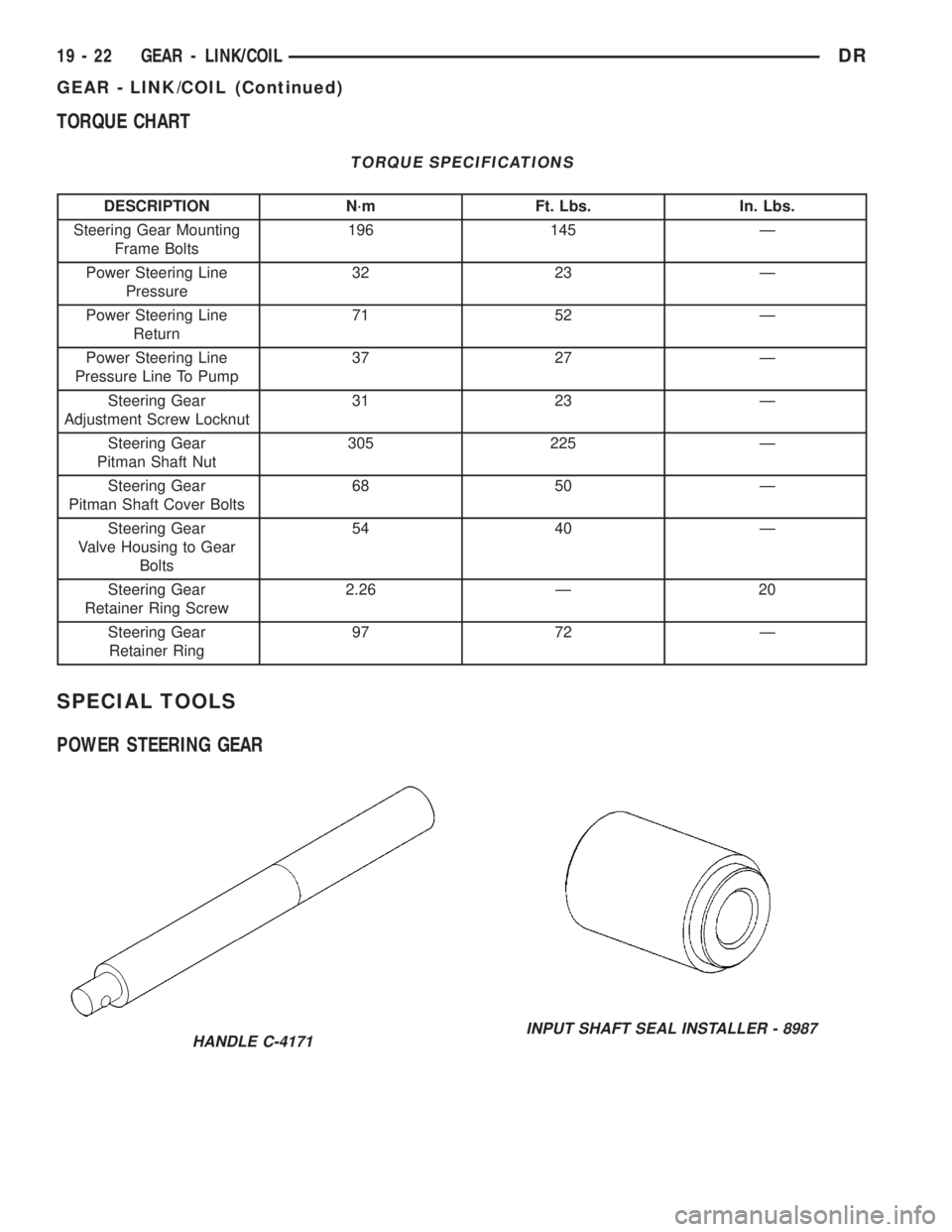
TORQUE CHART
TORQUE SPECIFICATIONS
DESCRIPTION N´m Ft. Lbs. In. Lbs.
Steering Gear Mounting
Frame Bolts196 145 Ð
Power Steering Line
Pressure32 23 Ð
Power Steering Line
Return71 52 Ð
Power Steering Line
Pressure Line To Pump37 27 Ð
Steering Gear
Adjustment Screw Locknut31 23 Ð
Steering Gear
Pitman Shaft Nut305 225 Ð
Steering Gear
Pitman Shaft Cover Bolts68 50 Ð
Steering Gear
Valve Housing to Gear
Bolts54 40 Ð
Steering Gear
Retainer Ring Screw2.26 Ð 20
Steering Gear
Retainer Ring97 72 Ð
SPECIAL TOOLS
POWER STEERING GEAR
HANDLE C-4171INPUT SHAFT SEAL INSTALLER - 8987
19 - 22 GEAR - LINK/COILDR
GEAR - LINK/COIL (Continued)
Page 1836 of 2895
HOSES - I.F.S.
REMOVAL
REMOVAL - RETURN HOSE - GEAR TO
COOLER
(1) Drain and siphon the power steering system.
(2) Raise and support the vehicle.
(3) Disconnect the return hose at the cooler.
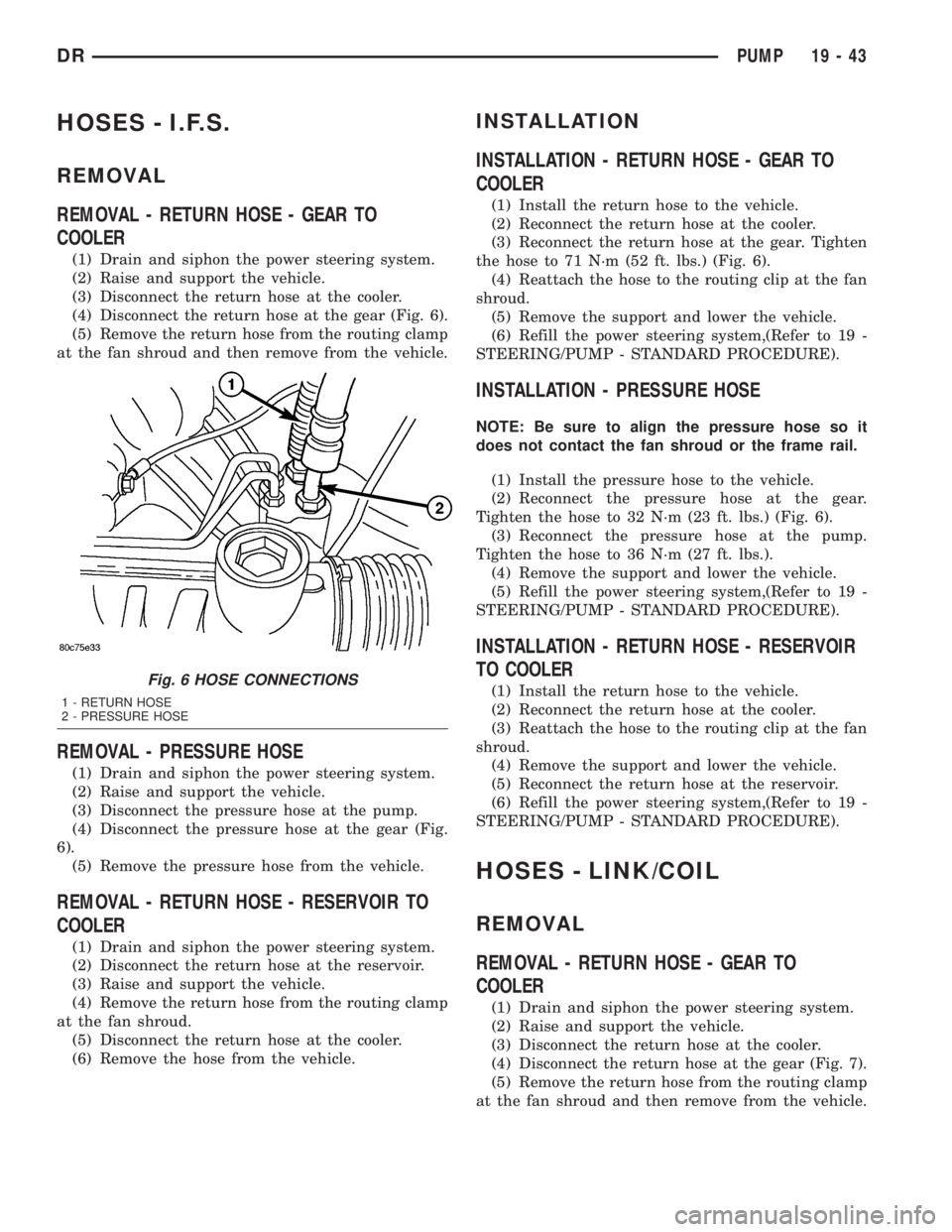
(4) Disconnect the return hose at the gear (Fig. 6).
(5) Remove the return hose from the routing clamp
at the fan shroud and then remove from the vehicle.
REMOVAL - PRESSURE HOSE
(1) Drain and siphon the power steering system.
(2) Raise and support the vehicle.
(3) Disconnect the pressure hose at the pump.
(4) Disconnect the pressure hose at the gear (Fig.
6).
(5) Remove the pressure hose from the vehicle.
REMOVAL - RETURN HOSE - RESERVOIR TO
COOLER
(1) Drain and siphon the power steering system.
(2) Disconnect the return hose at the reservoir.
(3) Raise and support the vehicle.
(4) Remove the return hose from the routing clamp
at the fan shroud.
(5) Disconnect the return hose at the cooler.
(6) Remove the hose from the vehicle.
INSTALLATION
INSTALLATION - RETURN HOSE - GEAR TO
COOLER
(1) Install the return hose to the vehicle.
(2) Reconnect the return hose at the cooler.
(3) Reconnect the return hose at the gear. Tighten
the hose to 71 N´m (52 ft. lbs.) (Fig. 6).
(4) Reattach the hose to the routing clip at the fan
shroud.
(5) Remove the support and lower the vehicle.
(6) Refill the power steering system,(Refer to 19 -
STEERING/PUMP - STANDARD PROCEDURE).
INSTALLATION - PRESSURE HOSE
NOTE: Be sure to align the pressure hose so it
does not contact the fan shroud or the frame rail.
(1) Install the pressure hose to the vehicle.
(2) Reconnect the pressure hose at the gear.
Tighten the hose to 32 N´m (23 ft. lbs.) (Fig. 6).
(3) Reconnect the pressure hose at the pump.
Tighten the hose to 36 N´m (27 ft. lbs.).
(4) Remove the support and lower the vehicle.
(5) Refill the power steering system,(Refer to 19 -
STEERING/PUMP - STANDARD PROCEDURE).
INSTALLATION - RETURN HOSE - RESERVOIR
TO COOLER
(1) Install the return hose to the vehicle.
(2) Reconnect the return hose at the cooler.
(3) Reattach the hose to the routing clip at the fan
shroud.
(4) Remove the support and lower the vehicle.
(5) Reconnect the return hose at the reservoir.
(6) Refill the power steering system,(Refer to 19 -
STEERING/PUMP - STANDARD PROCEDURE).
HOSES - LINK/COIL
REMOVAL
REMOVAL - RETURN HOSE - GEAR TO
COOLER
(1) Drain and siphon the power steering system.
(2) Raise and support the vehicle.
(3) Disconnect the return hose at the cooler.
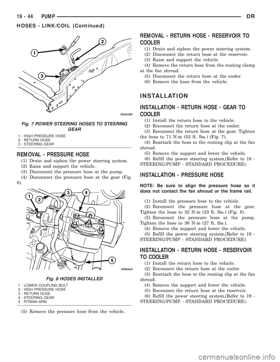
(4) Disconnect the return hose at the gear (Fig. 7).
(5) Remove the return hose from the routing clamp
at the fan shroud and then remove from the vehicle.
Fig. 6 HOSE CONNECTIONS
1 - RETURN HOSE
2 - PRESSURE HOSE
DRPUMP 19 - 43
Page 1837 of 2895
REMOVAL - PRESSURE HOSE
(1) Drain and siphon the power steering system.
(2) Raise and support the vehicle.
(3) Disconnect the pressure hose at the pump.
(4) Disconnect the pressure hose at the gear (Fig.
8).
(5) Remove the pressure hose from the vehicle.
REMOVAL - RETURN HOSE - RESERVOIR TO
COOLER
(1) Drain and siphon the power steering system.
(2) Disconnect the return hose at the reservoir.
(3) Raise and support the vehicle.
(4) Remove the return hose from the routing clamp
at the fan shroud.
(5) Disconnect the return hose at the cooler.
(6) Remove the hose from the vehicle.
INSTALLATION
INSTALLATION - RETURN HOSE - GEAR TO
COOLER
(1) Install the return hose to the vehicle.
(2) Reconnect the return hose at the cooler.
(3) Reconnect the return hose at the gear. Tighten
the hose to 71 N´m (52 ft. lbs.) (Fig. 7).
(4) Reattach the hose to the routing clip at the fan
shroud.
(5) Remove the support and lower the vehicle.
(6) Refill the power steering system,(Refer to 19 -
STEERING/PUMP - STANDARD PROCEDURE).
INSTALLATION - PRESSURE HOSE
NOTE: Be sure to align the pressure hose so it
does not contact the fan shroud or the frame rail.
(1) Install the pressure hose to the vehicle.
(2) Reconnect the pressure hose at the gear.
Tighten the hose to 32 N´m (23 ft. lbs.) (Fig. 8).
(3) Reconnect the pressure hose at the pump.
Tighten the hose to 36 N´m (27 ft. lbs.).
(4) Remove the support and lower the vehicle.
(5) Refill the power steering system,(Refer to 19 -
STEERING/PUMP - STANDARD PROCEDURE).
INSTALLATION - RETURN HOSE - RESERVOIR
TO COOLER
(1) Install the return hose to the vehicle.
(2) Reconnect the return hose at the cooler.
(3) Reattach the hose to the routing clip at the fan
shroud.
(4) Remove the support and lower the vehicle.
(5) Reconnect the return hose at the reservoir.
(6) Refill the power steering system,(Refer to 19 -
STEERING/PUMP - STANDARD PROCEDURE).
Fig. 7 POWER STEERING HOSES TO STEERING
GEAR
1 - HIGH PRESSURE HOSE
2 - RETURN HOSE
3 - STEERING GEAR
Fig. 8 HOSES INSTALLED
1 - LOWER COUPLING BOLT
2 - HIGH PRESSURE HOSE
3 - RETURN HOSE
4 - STEERING GEAR
5 - PITMAN ARM
19 - 44 PUMPDR
HOSES - LINK/COIL (Continued)
Page 1995 of 2895
STANDARD PROCEDURE - ALUMINUM
THREAD REPAIR
Damaged or worn threads in the aluminum trans-
mission case and valve body can be repaired by the
use of Heli-CoilsŸ, or equivalent. This repair con-
sists of drilling out the worn-out damaged threads.
Then tap the hole with a special Heli-CoilŸ tap, or
equivalent, and installing a Heli-CoilŸ insert, or
equivalent, into the hole. This brings the hole back to
its original thread size.
Heli-CoilŸ, or equivalent, tools and inserts are
readily available from most automotive parts suppli-
ers.
REMOVAL
NOTE: The overdrive unit can be removed and ser-
viced separately. It is not necessary to remove the
entire transmission assembly to perform overdrive
unit repairs.
(1) Disconnect battery negative cable.
(2) Raise vehicle.
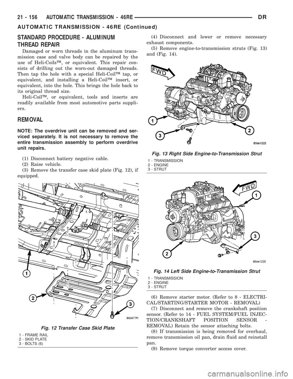
(3) Remove the transfer case skid plate (Fig. 12), if
equipped.(4) Disconnect and lower or remove necessary
exhaust components.
(5) Remove engine-to-transmission struts (Fig. 13)
and (Fig. 14).
(6) Remove starter motor. (Refer to 8 - ELECTRI-
CAL/STARTING/STARTER MOTOR - REMOVAL)
(7) Disconnect and remove the crankshaft position
sensor. (Refer to 14 - FUEL SYSTEM/FUEL INJEC-
TION/CRANKSHAFT POSITION SENSOR -
REMOVAL) Retain the sensor attaching bolts.
(8) If transmission is being removed for overhaul,
remove transmission oil pan, drain fluid and reinstall
pan.
(9) Remove torque converter access cover.
Fig. 12 Transfer Case Skid Plate
1 - FRAME RAIL
2 - SKID PLATE
3 - BOLTS (6)
Fig. 13 Right Side Engine-to-Transmission Strut
1 - TRANSMISSION
2 - ENGINE
3 - STRUT
Fig. 14 Left Side Engine-to-Transmission Strut
1 - TRANSMISSION
2 - ENGINE
3 - STRUT
21 - 156 AUTOMATIC TRANSMISSION - 46REDR
AUTOMATIC TRANSMISSION - 46RE (Continued)
Page 1996 of 2895
(10) Rotate crankshaft in clockwise direction until
converter bolts are accessible. Then remove bolts one
at a time. Rotate crankshaft with socket wrench on
dampener bolt.
(11) Mark propeller shaft and axle yokes for
assembly alignment. Then disconnect and remove
propeller shaft. On4x4models, remove both propel-
ler shafts. (Refer to 3 - DIFFERENTIAL & DRIV-
ELINE/PROPELLER SHAFT/PROPELLER SHAFT -
REMOVAL)
(12) Disconnect wires from the transmission range
sensor and transmission solenoid connector.
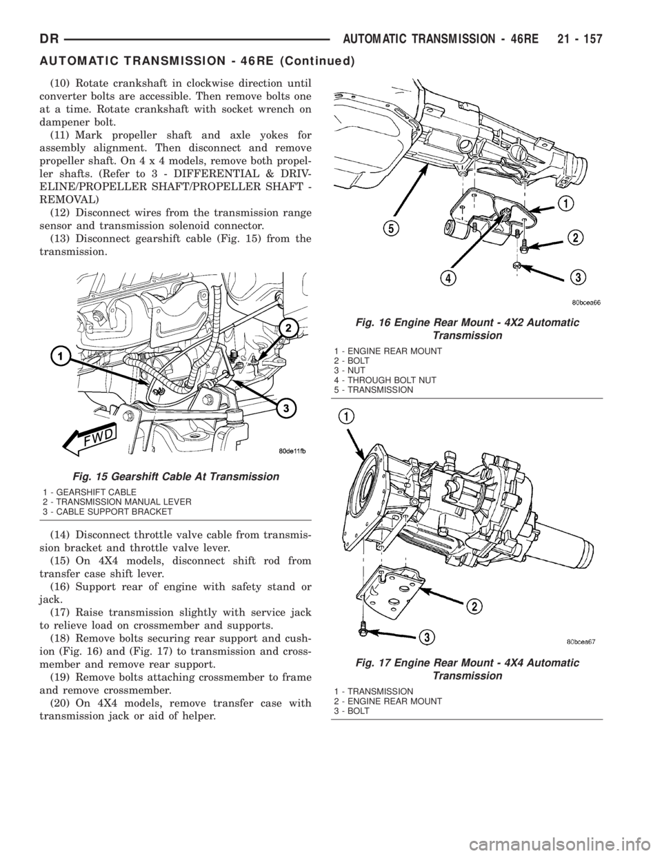
(13) Disconnect gearshift cable (Fig. 15) from the
transmission.
(14) Disconnect throttle valve cable from transmis-
sion bracket and throttle valve lever.
(15) On 4X4 models, disconnect shift rod from
transfer case shift lever.
(16) Support rear of engine with safety stand or
jack.
(17) Raise transmission slightly with service jack
to relieve load on crossmember and supports.
(18) Remove bolts securing rear support and cush-
ion (Fig. 16) and (Fig. 17) to transmission and cross-
member and remove rear support.
(19) Remove bolts attaching crossmember to frame
and remove crossmember.
(20) On 4X4 models, remove transfer case with
transmission jack or aid of helper.
Fig. 15 Gearshift Cable At Transmission
1 - GEARSHIFT CABLE
2 - TRANSMISSION MANUAL LEVER
3 - CABLE SUPPORT BRACKET
Fig. 16 Engine Rear Mount - 4X2 Automatic
Transmission
1 - ENGINE REAR MOUNT
2 - BOLT
3 - NUT
4 - THROUGH BOLT NUT
5 - TRANSMISSION
Fig. 17 Engine Rear Mount - 4X4 Automatic
Transmission
1 - TRANSMISSION
2 - ENGINE REAR MOUNT
3 - BOLT
DRAUTOMATIC TRANSMISSION - 46RE 21 - 157
AUTOMATIC TRANSMISSION - 46RE (Continued)