2003 DODGE RAM frame
[x] Cancel search: framePage 1696 of 2895
INSTALLATION
(1) Install the crossmember and install the bolts.
(2) Tighten the bolts to 102 N´m (75 ft. lbs.).
(3) Install the transmission mount nuts and
tighten to 61 N´m (45 ft. lbs.).
(4) Remove the transmission support.
(5) Install the transfercase skid plate. (Refer to 13
- FRAME & BUMPERS/FRAME/TRANSFER CASE
SKID PLATE - INSTALLATION)
TRAILER HITCH
REMOVAL
(1) Remove the rear bumper. (Refer to 13 -
FRAME & BUMPERS/BUMPERS/REAR BUMPER -
REMOVAL)
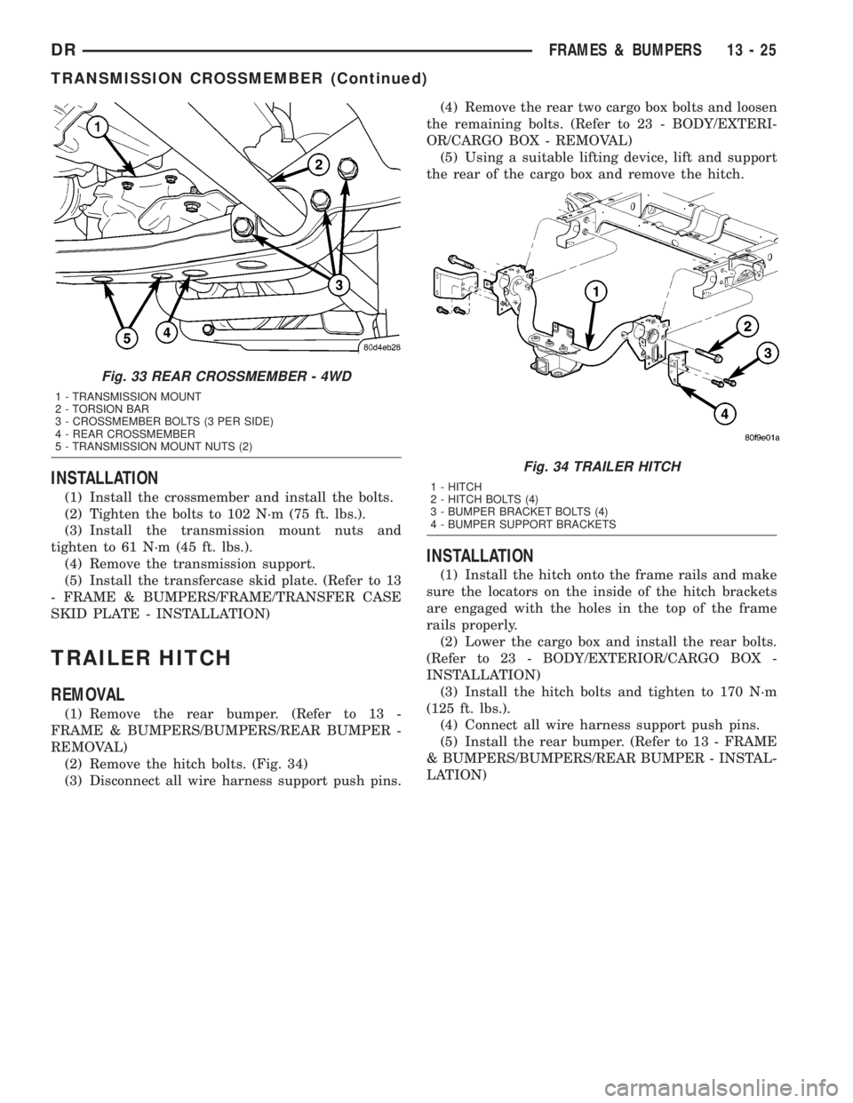
(2) Remove the hitch bolts. (Fig. 34)
(3) Disconnect all wire harness support push pins.(4) Remove the rear two cargo box bolts and loosen
the remaining bolts. (Refer to 23 - BODY/EXTERI-
OR/CARGO BOX - REMOVAL)
(5) Using a suitable lifting device, lift and support
the rear of the cargo box and remove the hitch.
INSTALLATION
(1) Install the hitch onto the frame rails and make
sure the locators on the inside of the hitch brackets
are engaged with the holes in the top of the frame
rails properly.
(2) Lower the cargo box and install the rear bolts.
(Refer to 23 - BODY/EXTERIOR/CARGO BOX -
INSTALLATION)
(3) Install the hitch bolts and tighten to 170 N´m
(125 ft. lbs.).
(4) Connect all wire harness support push pins.
(5) Install the rear bumper. (Refer to 13 - FRAME
& BUMPERS/BUMPERS/REAR BUMPER - INSTAL-
LATION)
Fig. 33 REAR CROSSMEMBER - 4WD
1 - TRANSMISSION MOUNT
2 - TORSION BAR
3 - CROSSMEMBER BOLTS (3 PER SIDE)
4 - REAR CROSSMEMBER
5 - TRANSMISSION MOUNT NUTS (2)
Fig. 34 TRAILER HITCH
1 - HITCH
2 - HITCH BOLTS (4)
3 - BUMPER BRACKET BOLTS (4)
4 - BUMPER SUPPORT BRACKETS
DRFRAMES & BUMPERS 13 - 25
TRANSMISSION CROSSMEMBER (Continued)
Page 1697 of 2895
TRANSFER CASE SKID PLATE
REMOVAL
(1) Raise and support the vehicle. (Refer to
LUBRICATION & MAINTENANCE/HOISTING -
STANDARD PROCEDURE)
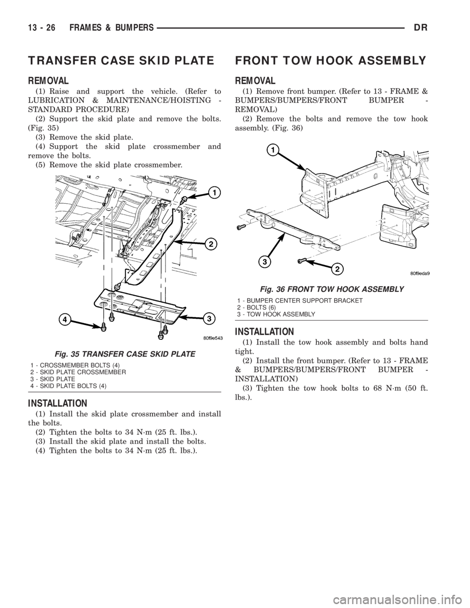
(2) Support the skid plate and remove the bolts.
(Fig. 35)
(3) Remove the skid plate.
(4) Support the skid plate crossmember and
remove the bolts.
(5) Remove the skid plate crossmember.
INSTALLATION
(1) Install the skid plate crossmember and install
the bolts.
(2) Tighten the bolts to 34 N´m (25 ft. lbs.).
(3) Install the skid plate and install the bolts.
(4) Tighten the bolts to 34 N´m (25 ft. lbs.).
FRONT TOW HOOK ASSEMBLY
REMOVAL
(1) Remove front bumper. (Refer to 13 - FRAME &
BUMPERS/BUMPERS/FRONT BUMPER -
REMOVAL)
(2) Remove the bolts and remove the tow hook
assembly. (Fig. 36)
INSTALLATION
(1) Install the tow hook assembly and bolts hand
tight.
(2) Install the front bumper. (Refer to 13 - FRAME
& BUMPERS/BUMPERS/FRONT BUMPER -
INSTALLATION)
(3) Tighten the tow hook bolts to 68 N´m (50 ft.
lbs.).
Fig. 35 TRANSFER CASE SKID PLATE
1 - CROSSMEMBER BOLTS (4)
2 - SKID PLATE CROSSMEMBER
3 - SKID PLATE
4 - SKID PLATE BOLTS (4)
Fig. 36 FRONT TOW HOOK ASSEMBLY
1 - BUMPER CENTER SUPPORT BRACKET
2 - BOLTS (6)
3 - TOW HOOK ASSEMBLY
13 - 26 FRAMES & BUMPERSDR
Page 1701 of 2895
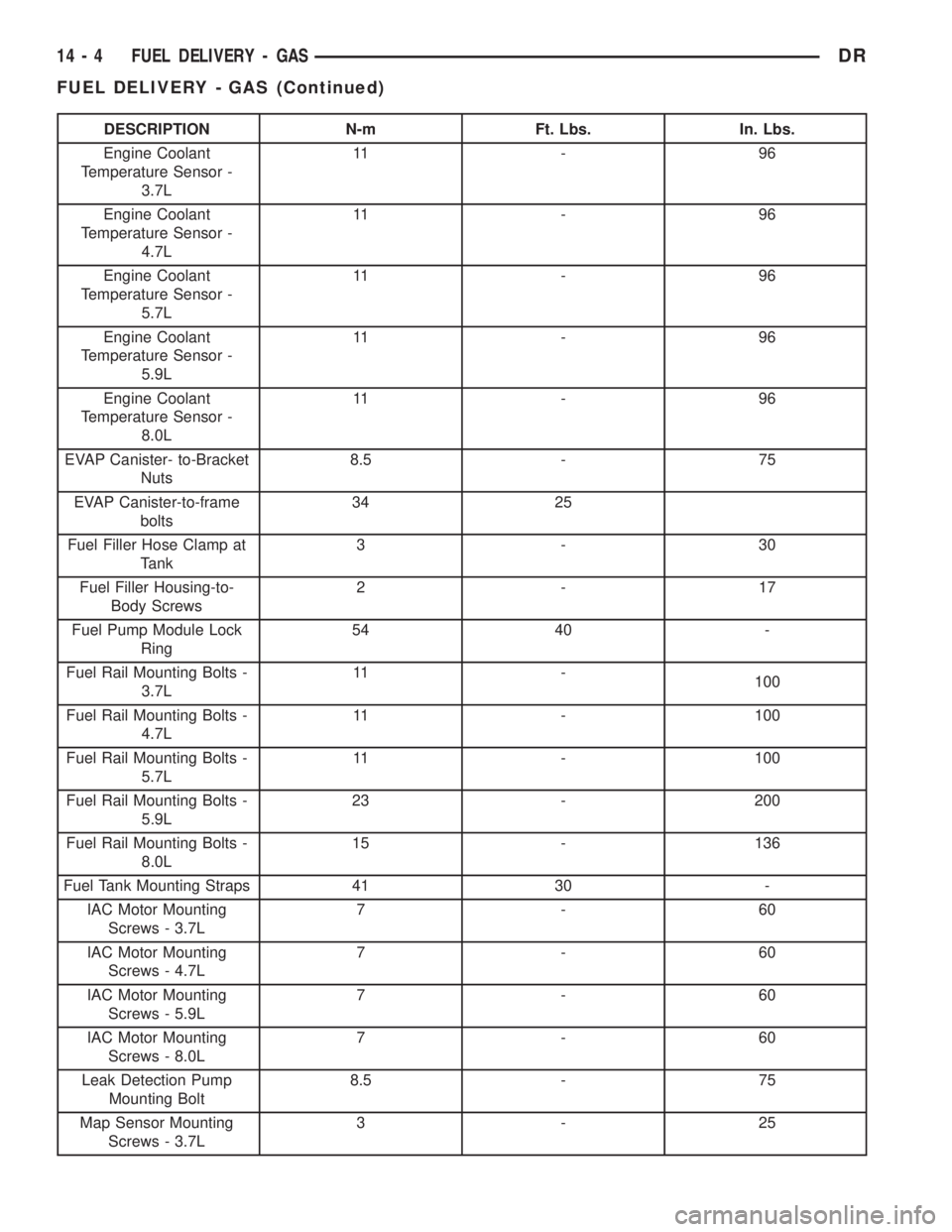
DESCRIPTION N-m Ft. Lbs. In. Lbs.
Engine Coolant
Temperature Sensor -
3.7L11 - 9 6
Engine Coolant
Temperature Sensor -
4.7L11 - 9 6
Engine Coolant
Temperature Sensor -
5.7L11 - 9 6
Engine Coolant
Temperature Sensor -
5.9L11 - 9 6
Engine Coolant
Temperature Sensor -
8.0L11 - 9 6
EVAP Canister- to-Bracket
Nuts8.5 - 75
EVAP Canister-to-frame
bolts34 25
Fuel Filler Hose Clamp at
Tank3-30
Fuel Filler Housing-to-
Body Screws2-17
Fuel Pump Module Lock
Ring54 40 -
Fuel Rail Mounting Bolts -
3.7L11 -
100
Fuel Rail Mounting Bolts -
4.7L11 - 100
Fuel Rail Mounting Bolts -
5.7L11 - 100
Fuel Rail Mounting Bolts -
5.9L23 - 200
Fuel Rail Mounting Bolts -
8.0L15 - 136
Fuel Tank Mounting Straps 41 30 -
IAC Motor Mounting
Screws - 3.7L7-60
IAC Motor Mounting
Screws - 4.7L7-60
IAC Motor Mounting
Screws - 5.9L7-60
IAC Motor Mounting
Screws - 8.0L7-60
Leak Detection Pump
Mounting Bolt8.5 - 75
Map Sensor Mounting
Screws - 3.7L3-25
14 - 4 FUEL DELIVERY - GASDR
FUEL DELIVERY - GAS (Continued)
Page 1703 of 2895
FUEL FILTER/PRESSURE
REGULATOR
DESCRIPTION
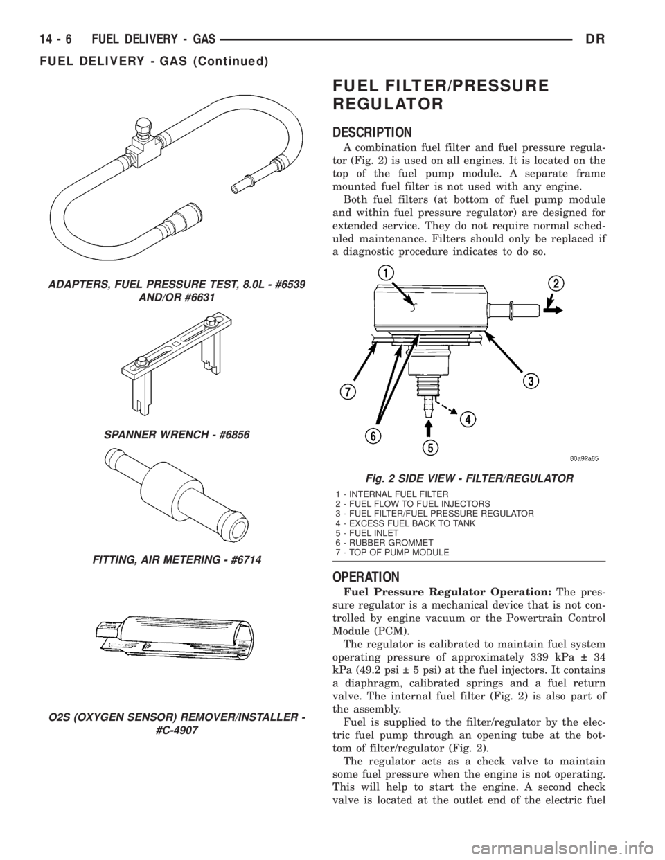
A combination fuel filter and fuel pressure regula-
tor (Fig. 2) is used on all engines. It is located on the
top of the fuel pump module. A separate frame
mounted fuel filter is not used with any engine.
Both fuel filters (at bottom of fuel pump module
and within fuel pressure regulator) are designed for
extended service. They do not require normal sched-
uled maintenance. Filters should only be replaced if
a diagnostic procedure indicates to do so.
OPERATION
Fuel Pressure Regulator Operation:The pres-
sure regulator is a mechanical device that is not con-
trolled by engine vacuum or the Powertrain Control
Module (PCM).
The regulator is calibrated to maintain fuel system
operating pressure of approximately 339 kPa 34
kPa (49.2 psi 5 psi) at the fuel injectors. It contains
a diaphragm, calibrated springs and a fuel return
valve. The internal fuel filter (Fig. 2) is also part of
the assembly.
Fuel is supplied to the filter/regulator by the elec-
tric fuel pump through an opening tube at the bot-
tom of filter/regulator (Fig. 2).
The regulator acts as a check valve to maintain
some fuel pressure when the engine is not operating.
This will help to start the engine. A second check
valve is located at the outlet end of the electric fuel
ADAPTERS, FUEL PRESSURE TEST, 8.0L - #6539
AND/OR #6631
SPANNER WRENCH - #6856
FITTING, AIR METERING - #6714
O2S (OXYGEN SENSOR) REMOVER/INSTALLER -
#C-4907
Fig. 2 SIDE VIEW - FILTER/REGULATOR
1 - INTERNAL FUEL FILTER
2 - FUEL FLOW TO FUEL INJECTORS
3 - FUEL FILTER/FUEL PRESSURE REGULATOR
4 - EXCESS FUEL BACK TO TANK
5 - FUEL INLET
6 - RUBBER GROMMET
7 - TOP OF PUMP MODULE
14 - 6 FUEL DELIVERY - GASDR
FUEL DELIVERY - GAS (Continued)
Page 1719 of 2895
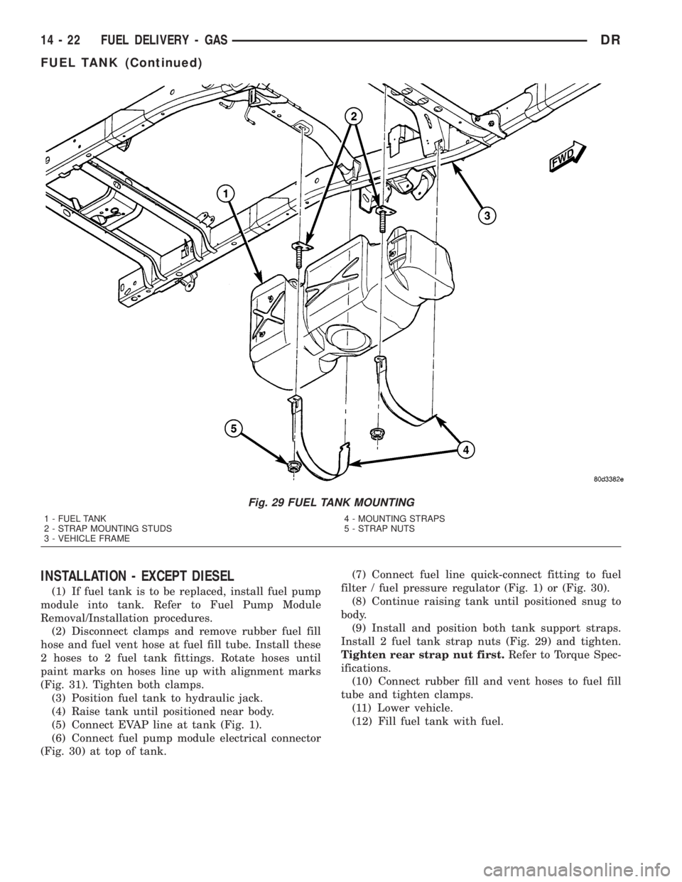
INSTALLATION - EXCEPT DIESEL
(1) If fuel tank is to be replaced, install fuel pump
module into tank. Refer to Fuel Pump Module
Removal/Installation procedures.
(2) Disconnect clamps and remove rubber fuel fill
hose and fuel vent hose at fuel fill tube. Install these
2 hoses to 2 fuel tank fittings. Rotate hoses until
paint marks on hoses line up with alignment marks
(Fig. 31). Tighten both clamps.
(3) Position fuel tank to hydraulic jack.
(4) Raise tank until positioned near body.
(5) Connect EVAP line at tank (Fig. 1).
(6) Connect fuel pump module electrical connector
(Fig. 30) at top of tank.(7) Connect fuel line quick-connect fitting to fuel
filter / fuel pressure regulator (Fig. 1) or (Fig. 30).
(8) Continue raising tank until positioned snug to
body.
(9) Install and position both tank support straps.
Install 2 fuel tank strap nuts (Fig. 29) and tighten.
Tighten rear strap nut first.Refer to Torque Spec-
ifications.
(10) Connect rubber fill and vent hoses to fuel fill
tube and tighten clamps.
(11) Lower vehicle.
(12) Fill fuel tank with fuel.
Fig. 29 FUEL TANK MOUNTING
1 - FUEL TANK
2 - STRAP MOUNTING STUDS
3 - VEHICLE FRAME4 - MOUNTING STRAPS
5 - STRAP NUTS
14 - 22 FUEL DELIVERY - GASDR
FUEL TANK (Continued)
Page 1771 of 2895
(7) If fuel tank is to be replaced, remove fuel tank
module from tank. Refer to Fuel Tank Module
Removal/Installation procedures.
INSTALLATION - DIESEL
(1) If fuel tank is to be replaced, install fuel tank
module into tank. Refer to Fuel Tank Module Remov-
al/Installation procedures.
(2) Position fuel tank to hydraulic jack.
(3) Raise tank until positioned near body.
(4) Connect fuel tank module electrical connector
at top of tank.
(5) Connect fuel supply and return lines to tank
module.(6) Continue raising tank until positioned snug to
body.
(7) Install and position both tank support straps.
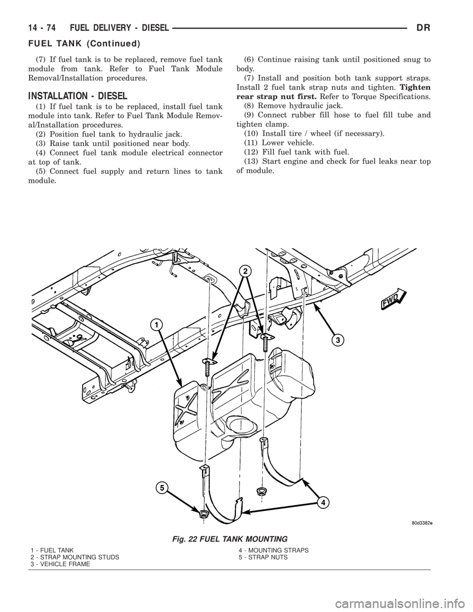
Install 2 fuel tank strap nuts and tighten.Tighten
rear strap nut first.Refer to Torque Specifications.
(8) Remove hydraulic jack.
(9) Connect rubber fill hose to fuel fill tube and
tighten clamp.
(10) Install tire / wheel (if necessary).
(11) Lower vehicle.
(12) Fill fuel tank with fuel.
(13) Start engine and check for fuel leaks near top
of module.
Fig. 22 FUEL TANK MOUNTING
1 - FUEL TANK
2 - STRAP MOUNTING STUDS
3 - VEHICLE FRAME4 - MOUNTING STRAPS
5 - STRAP NUTS
14 - 74 FUEL DELIVERY - DIESELDR
FUEL TANK (Continued)
Page 1773 of 2895
OPERATION
The purpose of the fuel transfer pump is to supply
(transfer) a low-pressure fuel source:fromthe fuel
tank,throughthe fuel filter/water separator andto
the fuel injection pump. Here, the low-pressure is
raised to a high-pressure by the fuel injection pump
for operation of the high-pressure fuel injectors.
Check valves within the pump, control direction of
fuel flow and prevent fuel bleed-back during engine
shut down.
Maximum current flow to the pump is 5 amperes.
With the engine running, the pump has a 100 per-
cent duty-cycle with a minimum pressure of 11.5 psi.
The transfer pump is self-priming: When the key is
first turned on (without cranking engine), the pump
will operate for approximately 1/2 second and then
shut off. The pump will also operate for up to 25 sec-
onds after the starter is engaged, and then disen-
gaged and the engine is not running. The pump
shuts off immediately if the key is on and the engine
stops running.
The fuel volume of the transfer pump will always
provide more fuel than the fuel injection pump
requires. Excess fuel is returned from the injection
pump through an overflow valve, and then back to
the fuel tank.
REMOVAL
The fuel transfer pump (fuel lift pump) is attached
to the rear of the fuel filter/water separator housing
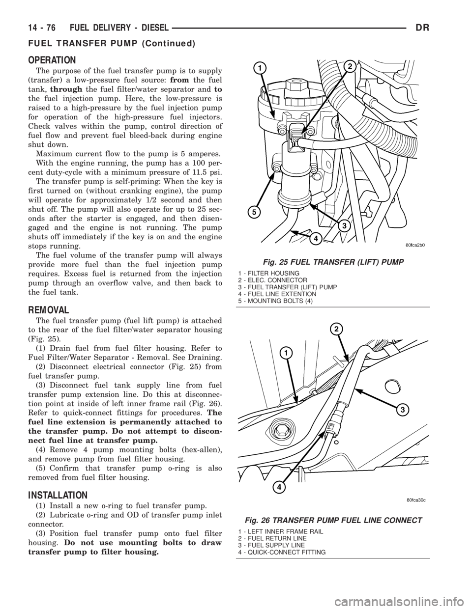
(Fig. 25).
(1) Drain fuel from fuel filter housing. Refer to
Fuel Filter/Water Separator - Removal. See Draining.
(2) Disconnect electrical connector (Fig. 25) from
fuel transfer pump.
(3) Disconnect fuel tank supply line from fuel
transfer pump extension line. Do this at disconnec-
tion point at inside of left inner frame rail (Fig. 26).
Refer to quick-connect fittings for procedures.The
fuel line extension is permanently attached to
the transfer pump. Do not attempt to discon-
nect fuel line at transfer pump.
(4) Remove 4 pump mounting bolts (hex-allen),
and remove pump from fuel filter housing.
(5) Confirm that transfer pump o-ring is also
removed from fuel filter housing.
INSTALLATION
(1) Install a new o-ring to fuel transfer pump.
(2) Lubricate o-ring and OD of transfer pump inlet
connector.
(3) Position fuel transfer pump onto fuel filter
housing.Do not use mounting bolts to draw
transfer pump to filter housing.
Fig. 25 FUEL TRANSFER (LIFT) PUMP
1 - FILTER HOUSING
2 - ELEC. CONNECTOR
3 - FUEL TRANSFER (LIFT) PUMP
4 - FUEL LINE EXTENTION
5 - MOUNTING BOLTS (4)
Fig. 26 TRANSFER PUMP FUEL LINE CONNECT
1 - LEFT INNER FRAME RAIL
2 - FUEL RETURN LINE
3 - FUEL SUPPLY LINE
4 - QUICK-CONNECT FITTING
14 - 76 FUEL DELIVERY - DIESELDR
FUEL TRANSFER PUMP (Continued)
Page 1809 of 2895
GEAR - INDEPENDENT FRONT SUSPENSION
TABLE OF CONTENTS
page page
GEAR - INDEPENDENT FRONT SUSPENSION
DESCRIPTION.........................16
REMOVAL.............................16
INSTALLATION.........................17
SPECIFICATIONS
TORQUE CHART......................18BUSHING
REMOVAL.............................18
INSTALLATION.........................18
GEAR - INDEPENDENT FRONT
SUSPENSION
DESCRIPTION
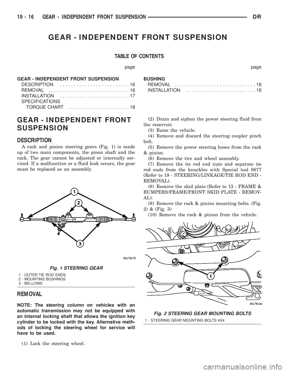
A rack and pinion steering gears (Fig. 1) is made
up of two main components, the pinon shaft and the
rack. The gear cannot be adjusted or internally ser-
viced. If a malfunction or a fluid leak occurs, the gear
must be replaced as an assembly.
REMOVAL
NOTE: The steering column on vehicles with an
automatic transmission may not be equipped with
an internal locking shaft that allows the ignition key
cylinder to be locked with the key. Alternative meth-
ods of locking the steering wheel for service will
have to be used.
(1) Lock the steering wheel.(2) Drain and siphon the power steering fluid from
the reservoir.
(3) Raise the vehicle.
(4) Remove and discard the steering coupler pinch
bolt.
(5) Remove the power steering hoses from the rack
& pinion.
(6) Remove the tire and wheel assembly.
(7) Remove the tie rod end nuts and separate tie
rod ends from the knuckles with Special tool 8677
(Refer to 19 - STEERING/LINKAGE/TIE ROD END -
REMOVAL).
(8) Remove the skid plate (Refer to 13 - FRAME &
BUMPERS/FRAME/FRONT SKID PLATE - REMOV-
AL).
(9) Remove the rack & pinion mounting bolts. (Fig.
2) & (Fig. 3)
(10) Remove the rack & pinion from the vehicle.
Fig. 1 STEERING GEAR
1 - OUTER TIE ROD ENDS
2 - MOUNTING BUSHINGS
3 - BELLOWS
Fig. 2 STEERING GEAR MOUNTING BOLTS
1 - STEERING GEAR MOUNTING BOLTS 4X4
19 - 16 GEAR - INDEPENDENT FRONT SUSPENSIONDR