2003 DODGE RAM frame
[x] Cancel search: framePage 2176 of 2895
STANDARD PROCEDURE - ALUMINUM
THREAD REPAIR
Damaged or worn threads in the aluminum trans-
mission case and valve body can be repaired by the
use of Heli-CoilsŸ, or equivalent. This repair con-
sists of drilling out the worn-out damaged threads.
Then tap the hole with a special Heli-CoilŸ tap, or
equivalent, and installing a Heli-CoilŸ insert, or
equivalent, into the hole. This brings the hole back to
its original thread size.
Heli-CoilŸ, or equivalent, tools and inserts are
readily available from most automotive parts suppli-
ers.
REMOVAL
NOTE: The overdrive unit can be removed and ser-
viced separately. It is not necessary to remove the
entire transmission assembly to perform overdrive
unit repairs.
(1) Disconnect battery negative cable.
(2) Raise vehicle.
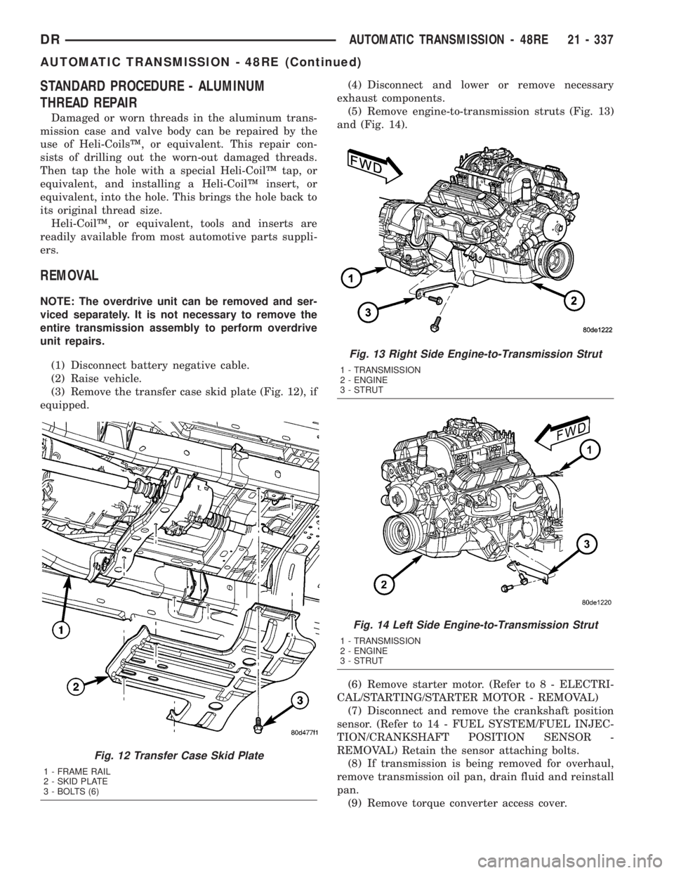
(3) Remove the transfer case skid plate (Fig. 12), if
equipped.(4) Disconnect and lower or remove necessary
exhaust components.
(5) Remove engine-to-transmission struts (Fig. 13)
and (Fig. 14).
(6) Remove starter motor. (Refer to 8 - ELECTRI-
CAL/STARTING/STARTER MOTOR - REMOVAL)
(7) Disconnect and remove the crankshaft position
sensor. (Refer to 14 - FUEL SYSTEM/FUEL INJEC-
TION/CRANKSHAFT POSITION SENSOR -
REMOVAL) Retain the sensor attaching bolts.
(8) If transmission is being removed for overhaul,
remove transmission oil pan, drain fluid and reinstall
pan.
(9) Remove torque converter access cover.
Fig. 12 Transfer Case Skid Plate
1 - FRAME RAIL
2 - SKID PLATE
3 - BOLTS (6)
Fig. 13 Right Side Engine-to-Transmission Strut
1 - TRANSMISSION
2 - ENGINE
3 - STRUT
Fig. 14 Left Side Engine-to-Transmission Strut
1 - TRANSMISSION
2 - ENGINE
3 - STRUT
DRAUTOMATIC TRANSMISSION - 48RE 21 - 337
AUTOMATIC TRANSMISSION - 48RE (Continued)
Page 2177 of 2895
(10) Rotate crankshaft in clockwise direction until
converter bolts are accessible. Then remove bolts one
at a time. Rotate crankshaft with socket wrench on
dampener bolt.
(11) Mark propeller shaft and axle yokes for
assembly alignment. Then disconnect and remove
propeller shaft. On4x4models, remove both propel-
ler shafts. (Refer to 3 - DIFFERENTIAL & DRIV-
ELINE/PROPELLER SHAFT/PROPELLER SHAFT -
REMOVAL)
(12) Disconnect wires from the transmission range
sensor and transmission solenoid connector.
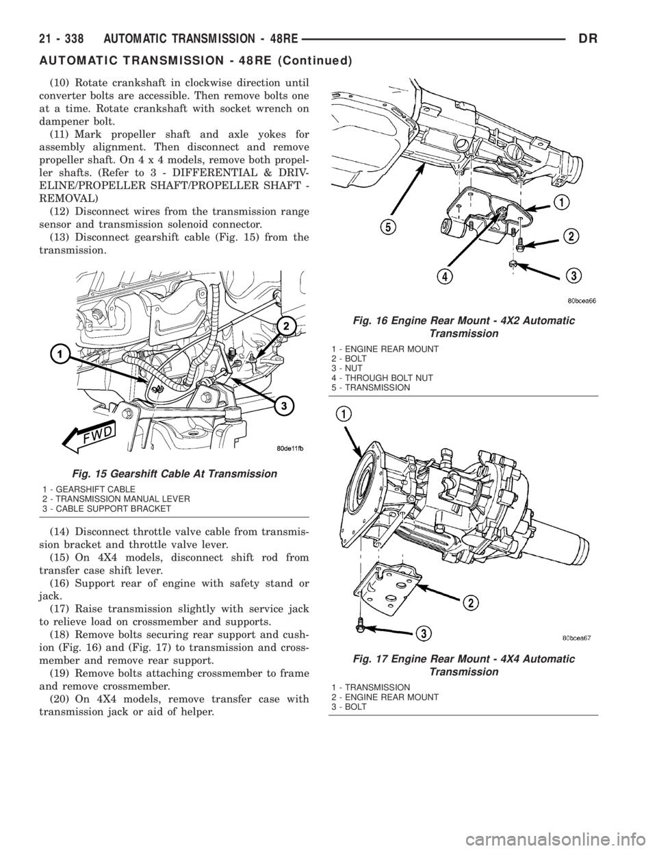
(13) Disconnect gearshift cable (Fig. 15) from the
transmission.
(14) Disconnect throttle valve cable from transmis-
sion bracket and throttle valve lever.
(15) On 4X4 models, disconnect shift rod from
transfer case shift lever.
(16) Support rear of engine with safety stand or
jack.
(17) Raise transmission slightly with service jack
to relieve load on crossmember and supports.
(18) Remove bolts securing rear support and cush-
ion (Fig. 16) and (Fig. 17) to transmission and cross-
member and remove rear support.
(19) Remove bolts attaching crossmember to frame
and remove crossmember.
(20) On 4X4 models, remove transfer case with
transmission jack or aid of helper.
Fig. 15 Gearshift Cable At Transmission
1 - GEARSHIFT CABLE
2 - TRANSMISSION MANUAL LEVER
3 - CABLE SUPPORT BRACKET
Fig. 16 Engine Rear Mount - 4X2 Automatic
Transmission
1 - ENGINE REAR MOUNT
2 - BOLT
3 - NUT
4 - THROUGH BOLT NUT
5 - TRANSMISSION
Fig. 17 Engine Rear Mount - 4X4 Automatic
Transmission
1 - TRANSMISSION
2 - ENGINE REAR MOUNT
3 - BOLT
21 - 338 AUTOMATIC TRANSMISSION - 48REDR
AUTOMATIC TRANSMISSION - 48RE (Continued)
Page 2334 of 2895
NOTE: The air supply which is used must be free of
moisture and dirt. Use a pressure of 30 psi to test
clutch operation.
Apply air pressure at each port. If the clutch is
functioning, a soft thump will be heard as the clutch
is applied. The clutch application can also be felt by
touching the appropriate element while applying air
pressure. As the air pressure is released, the clutch
should also release.
DIAGNOSIS AND TESTING - CONVERTER
HOUSING FLUID LEAK
When diagnosing converter housing fluid leaks,
two items must be established before repair.
(1) Verify that a leak condition actually exists.
(2) Determined the true source of the leak.
Some suspected converter housing fluid leaks may not
be leaks at all. They may only be the result of residual
fluid in the converter housing, or excess fluid spilled dur-
ing factory fill or fill after repair. Converter housing
leaks have several potential sources. Through careful
observation, a leak source can be identified before remov-
ing the transmission for repair. Torque converter seal
leaks tend to move along the drive hub and onto the rear
of the converter. Pump cover seal tend to run down the
cover and the inside surface of the bellhousing.
Some leaks, or suspected leaks, may be particu-
larly difficult to locate. If necessary, a Mopart
approved dye may be used to locate a leak.
TORQUE CONVERTER LEAK POINTS
Possible sources of converter leaks are:
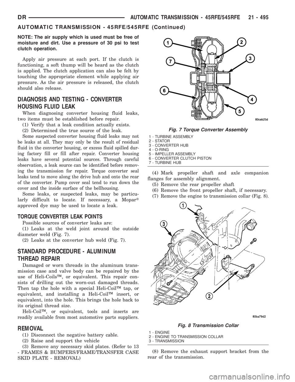
(1) Leaks at the weld joint around the outside
diameter weld (Fig. 7).
(2) Leaks at the converter hub weld (Fig. 7).
STANDARD PROCEDURE - ALUMINUM
THREAD REPAIR
Damaged or worn threads in the aluminum trans-
mission case and valve body can be repaired by the
use of Heli-CoilsŸ, or equivalent. This repair con-
sists of drilling out the worn-out damaged threads.
Then tap the hole with a special Heli-CoilŸ tap, or
equivalent, and installing a Heli-CoilŸ insert, or
equivalent, into the hole. This brings the hole back to
its original thread size.
Heli-CoilŸ, or equivalent, tools and inserts are
readily available from most automotive parts suppliers.
REMOVAL
(1) Disconnect the negative battery cable.
(2) Raise and support the vehicle
(3) Remove any necessary skid plates. (Refer to 13
- FRAMES & BUMPERS/FRAME/TRANSFER CASE
SKID PLATE - REMOVAL)(4) Mark propeller shaft and axle companion
flanges for assembly alignment.
(5) Remove the rear propeller shaft
(6) Remove the front propeller shaft, if necessary.
(7)
Remove the engine to transmission collar (Fig. 8).
(8) Remove the exhaust support bracket from the
rear of the transmission.
Fig. 7 Torque Converter Assembly
1 - TURBINE ASSEMBLY
2-STATOR
3 - CONVERTER HUB
4 - O-RING
5 - IMPELLER ASSEMBLY
6 - CONVERTER CLUTCH PISTON
7 - TURBINE HUB
Fig. 8 Transmission Collar
1 - ENGINE
2 - ENGINE TO TRANSMISSION COLLAR
3 - TRANSMISSION
DRAUTOMATIC TRANSMISSION - 45RFE/545RFE 21 - 495
AUTOMATIC TRANSMISSION - 45RFE/545RFE (Continued)
Page 2351 of 2895
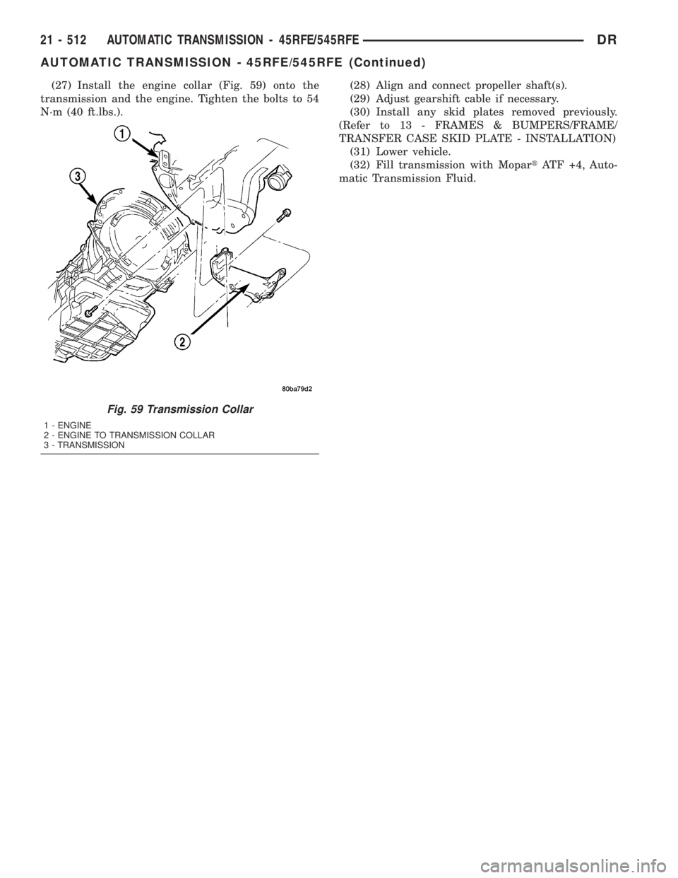
(27) Install the engine collar (Fig. 59) onto the
transmission and the engine. Tighten the bolts to 54
N´m (40 ft.lbs.).(28) Align and connect propeller shaft(s).
(29) Adjust gearshift cable if necessary.
(30) Install any skid plates removed previously.
(Refer to 13 - FRAMES & BUMPERS/FRAME/
TRANSFER CASE SKID PLATE - INSTALLATION)
(31) Lower vehicle.
(32) Fill transmission with MopartATF +4, Auto-
matic Transmission Fluid.
Fig. 59 Transmission Collar
1 - ENGINE
2 - ENGINE TO TRANSMISSION COLLAR
3 - TRANSMISSION
21 - 512 AUTOMATIC TRANSMISSION - 45RFE/545RFEDR
AUTOMATIC TRANSMISSION - 45RFE/545RFE (Continued)
Page 2432 of 2895
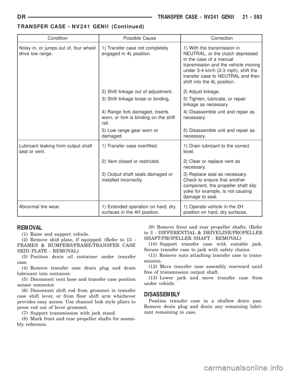
Condition Possible Cause Correction
Noisy in, or jumps out of, four wheel
drive low range.1) Transfer case not completely
engaged in 4L position.1) With the transmission in
NEUTRAL, or the clutch depressed
in the case of a manual
transmission and the vehicle moving
under 3-4 km/h (2-3 mph), shift the
transfer case to NEUTRAL and then
shift into the 4L position.
2) Shift linkage out of adjustment. 2) Adjust linkage.
3) Shift linkage loose or binding. 3) Tighten, lubricate, or repair
linkage as necessary.
4) Range fork damaged, inserts
worn, or fork is binding on the shift
rail.4) Disassemble unit and repair as
necessary.
5) Low range gear worn or
damaged.5) Disassemble unit and repair as
necessary.
Lubricant leaking from output shaft
seal or vent.1) Transfer case overfilled. 1) Drain lubricant to the correct
level.
2) Vent closed or restricted. 2) Clear or replace vent as
necessary.
3) Output shaft seals damaged or
installed incorrectly.3) Replace seal as necessary.
Check to ensure that another
component, the propeller shaft slip
yoke for example, is not causing
damage to seal.
Abnormal tire wear. 1) Extended operation on hard, dry
surfaces in the 4H position.1) Operate vehicle in the 2H
position on hard, dry surfaces.
REMOVAL
(1) Raise and support vehicle.
(2) Remove skid plate, if equipped. (Refer to 13 -
FRAMES & BUMPERS/FRAME/TRANSFER CASE
SKID PLATE - REMOVAL)
(3) Position drain oil container under transfer
case.
(4) Remove transfer case drain plug and drain
lubricant into container.
(5) Disconnect vent hose and transfer case position
sensor connector.
(6) Disconnect shift rod from grommet in transfer
case shift lever, or from floor shift arm whichever
provides easy access. Use channel lock style pliers to
press rod out of lever grommet.
(7) Support transmission with jack stand.
(8) Mark front and rear propeller shafts for assem-
bly reference.(9) Remove front and rear propeller shafts. (Refer
to 3 - DIFFERENTIAL & DRIVELINE/PROPELLER
SHAFT/PROPELLER SHAFT - REMOVAL)
(10) Support transfer case with suitable jack.
Secure transfer case to jack with safety chains.
(11) Remove nuts attaching transfer case to trans-
mission.
(12) Move transfer case assembly rearward until
free of transmission output shaft.
(13) Lower jack and move transfer case from
under vehicle.
DISASSEMBLY
Position transfer case in a shallow drain pan.
Remove drain plug and drain any remaining lubri-
cant remaining in case.
DRTRANSFER CASE - NV241 GENII 21 - 593
TRANSFER CASE - NV241 GENII (Continued)
Page 2453 of 2895
REAR EXTENSION
(1) Install new seal in rear extension housing seal
with Installer D-163 and Handle C-4171..
(2) Apply bead of MopartGasket Maker, or equiv-
alent, to mating surface of rear extension housing.
Keep sealer bead width to maximum of 3/16 inch. Do
not use excessive amount of sealer as excess could be
displaced into output bearing.
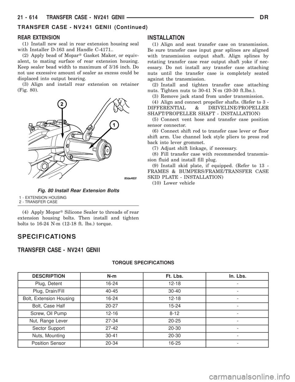
(3) Align and install rear extension on retainer
(Fig. 80).
(4) Apply MopartSilicone Sealer to threads of rear
extension housing bolts. Then install and tighten
bolts to 16-24 N´m (12-18 ft. lbs.) torque.
INSTALLATION
(1) Align and seat transfer case on transmission.
Be sure transfer case input gear splines are aligned
with transmission output shaft. Align splines by
rotating transfer case rear output shaft yoke if nec-
essary. Do not install any transfer case attaching
nuts until the transfer case is completely seated
against the transmission.
(2) Install and tighten transfer case attaching
nuts. Tighten nuts to 30-41 N´m (20-30 ft.lbs.).
(3) Remove jack stand from under transmission.
(4) Align and connect propeller shafts. (Refer to 3 -
DIFFERENTIAL & DRIVELINE/PROPELLER
SHAFT/PROPELLER SHAFT - INSTALLATION)
(5) Connect vent hose and transfer case position
sensor connector.
(6) Connect shift rod to transfer case lever or floor
shift arm. Use channel lock style pliers to press rod
back into lever grommet.
(7) Adjust shift linkage, if necessary.
(8) Fill transfer case with recommended transmis-
sion fluid and install fill plug.
(9) Install skid plate, if equipped. (Refer to 13 -
FRAMES & BUMPERS/FRAME/TRANSFER CASE
SKID PLATE - INSTALLATION)
(10) Lower vehicle
SPECIFICATIONS
TRANSFER CASE - NV241 GENII
TORQUE SPECIFICATIONS
DESCRIPTION N-m Ft. Lbs. In. Lbs.
Plug, Detent 16-24 12-18 -
Plug, Drain/Fill 40-45 30-40 -
Bolt, Extension Housing 16-24 12-18 -
Bolt, Case Half 20-27 15-24 -
Screw, Oil Pump 12-16 8-12 -
Nut, Range Lever 27-34 20-25 -
Sector Support 27-42 20-30 -
Nuts, Mounting 30-41 20-30 -
Position Sensor 20-34 16-25 -
Fig. 80 Install Rear Extension Bolts
1 - EXTENSION HOUSING
2 - TRANSFER CASE
21 - 614 TRANSFER CASE - NV241 GENIIDR
TRANSFER CASE - NV241 GENII (Continued)
Page 2464 of 2895
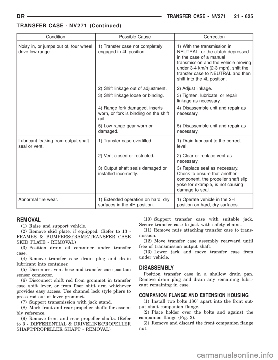
Condition Possible Cause Correction
Noisy in, or jumps out of, four wheel
drive low range.1) Transfer case not completely
engaged in 4L position.1) With the transmission in
NEUTRAL, or the clutch depressed
in the case of a manual
transmission and the vehicle moving
under 3-4 km/h (2-3 mph), shift the
transfer case to NEUTRAL and then
shift into the 4L position.
2) Shift linkage out of adjustment. 2) Adjust linkage.
3) Shift linkage loose or binding. 3) Tighten, lubricate, or repair
linkage as necessary.
4) Range fork damaged, inserts
worn, or fork is binding on the shift
rail.4) Disassemble unit and repair as
necessary.
5) Low range gear worn or
damaged.5) Disassemble unit and repair as
necessary.
Lubricant leaking from output shaft
seal or vent.1) Transfer case overfilled. 1) Drain lubricant to the correct
level.
2) Vent closed or restricted. 2) Clear or replace vent as
necessary.
3) Output shaft seals damaged or
installed incorrectly.3) Replace seal as necessary.
Check to ensure that another
component, the propeller shaft slip
yoke for example, is not causing
damage to seal.
Abnormal tire wear. 1) Extended operation on hard, dry
surfaces in the 4H position.1) Operate vehicle in the 2H
position on hard, dry surfaces.
REMOVAL
(1) Raise and support vehicle.
(2) Remove skid plate, if equipped. (Refer to 13 -
FRAMES & BUMPERS/FRAME/TRANSFER CASE
SKID PLATE - REMOVAL)
(3) Position drain oil container under transfer
case.
(4) Remove transfer case drain plug and drain
lubricant into container.
(5) Disconnect vent hose and transfer case position
sensor connector.
(6) Disconnect shift rod from grommet in transfer
case shift lever, or from floor shift arm whichever
provides easy access. Use channel lock style pliers to
press rod out of lever grommet.
(7) Support transmission with jack stand.
(8) Mark front and rear propeller shafts for assem-
bly reference.
(9) Remove front and rear propeller shafts. (Refer
to 3 - DIFFERENTIAL & DRIVELINE/PROPELLER
SHAFT/PROPELLER SHAFT - REMOVAL)(10) Support transfer case with suitable jack.
Secure transfer case to jack with safety chains.
(11) Remove nuts attaching transfer case to trans-
mission.
(12) Move transfer case assembly rearward until
free of transmission output shaft.
(13) Lower jack and move transfer case from
under vehicle.
DISASSEMBLY
Position transfer case in a shallow drain pan.
Remove drain plug and drain any remaining lubri-
cant remaining in case.
COMPANION FLANGE AND EXTENSION HOUSING
(1) Install two bolts 180É apart into the front out-
put shaft companion flange.
(2) Place holder over the bolts and against the
companion flange (Fig. 3).
(3) Remove and discard the front companion flange
nut.
DRTRANSFER CASE - NV271 21 - 625
TRANSFER CASE - NV271 (Continued)
Page 2488 of 2895
(7) Install the front companion flange onto the
front output shaft.
(8) Install two bolts 180É apart into the front out-
put shaft companion flange.
(9) Place holder over the bolts and against the
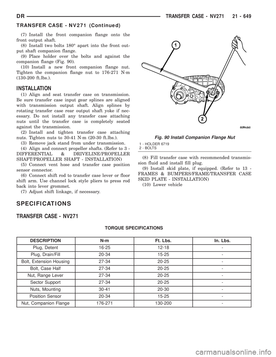
companion flange (Fig. 90).
(10) Install a new front companion flange nut.
Tighten the companion flange nut to 176-271 N´m
(130-200 ft.lbs.).
INSTALLATION
(1) Align and seat transfer case on transmission.
Be sure transfer case input gear splines are aligned
with transmission output shaft. Align splines by
rotating transfer case rear output shaft yoke if nec-
essary. Do not install any transfer case attaching
nuts until the transfer case is completely seated
against the transmission.
(2) Install and tighten transfer case attaching
nuts. Tighten nuts to 30-41 N´m (20-30 ft.lbs.).
(3) Remove jack stand from under transmission.
(4) Align and connect propeller shafts. (Refer to 3 -
DIFFERENTIAL & DRIVELINE/PROPELLER
SHAFT/PROPELLER SHAFT - INSTALLATION)
(5) Connect vent hose and transfer case position
sensor connector.
(6) Connect shift rod to transfer case lever or floor
shift arm. Use channel lock style pliers to press rod
back into lever grommet.
(7) Adjust shift linkage, if necessary.(8) Fill transfer case with recommended transmis-
sion fluid and install fill plug.
(9) Install skid plate, if equipped. (Refer to 13 -
FRAMES & BUMPERS/FRAME/TRANSFER CASE
SKID PLATE - INSTALLATION)
(10) Lower vehicle
SPECIFICATIONS
TRANSFER CASE - NV271
TORQUE SPECIFICATIONS
DESCRIPTION N-m Ft. Lbs. In. Lbs.
Plug, Detent 16-25 12-18 -
Plug, Drain/Fill 20-34 15-25 -
Bolt, Extension Housing 27-34 20-25 -
Bolt, Case Half 27-34 20-25 -
Nut, Range Lever 27-34 20-25 -
Sector Support 27-34 20-25 -
Nuts, Mounting 30-41 20-30 -
Position Sensor 20-34 15-25 -
Nut, Companion Flange 176-271 130-200 -
Fig. 90 Install Companion Flange Nut
1 - HOLDER 6719
2 - BOLTS
DRTRANSFER CASE - NV271 21 - 649
TRANSFER CASE - NV271 (Continued)