2003 DODGE RAM frame
[x] Cancel search: framePage 2697 of 2895
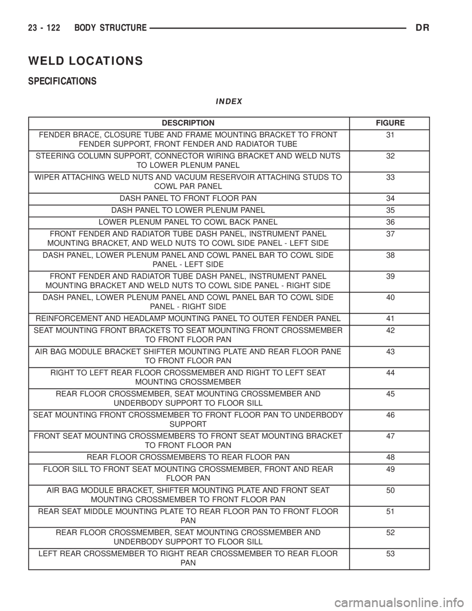
WELD LOCATIONS
SPECIFICATIONS
INDEX
DESCRIPTION FIGURE
FENDER BRACE, CLOSURE TUBE AND FRAME MOUNTING BRACKET TO FRONT
FENDER SUPPORT, FRONT FENDER AND RADIATOR TUBE31
STEERING COLUMN SUPPORT, CONNECTOR WIRING BRACKET AND WELD NUTS
TO LOWER PLENUM PANEL32
WIPER ATTACHING WELD NUTS AND VACUUM RESERVOIR ATTACHING STUDS TO
COWL PAR PANEL33
DASH PANEL TO FRONT FLOOR PAN 34
DASH PANEL TO LOWER PLENUM PANEL 35
LOWER PLENUM PANEL TO COWL BACK PANEL 36
FRONT FENDER AND RADIATOR TUBE DASH PANEL, INSTRUMENT PANEL
MOUNTING BRACKET, AND WELD NUTS TO COWL SIDE PANEL - LEFT SIDE37
DASH PANEL, LOWER PLENUM PANEL AND COWL PANEL BAR TO COWL SIDE
PANEL - LEFT SIDE38
FRONT FENDER AND RADIATOR TUBE DASH PANEL, INSTRUMENT PANEL
MOUNTING BRACKET AND WELD NUTS TO COWL SIDE PANEL - RIGHT SIDE39
DASH PANEL, LOWER PLENUM PANEL AND COWL PANEL BAR TO COWL SIDE
PANEL - RIGHT SIDE40
REINFORCEMENT AND HEADLAMP MOUNTING PANEL TO OUTER FENDER PANEL 41
SEAT MOUNTING FRONT BRACKETS TO SEAT MOUNTING FRONT CROSSMEMBER
TO FRONT FLOOR PAN42
AIR BAG MODULE BRACKET SHIFTER MOUNTING PLATE AND REAR FLOOR PANE
TO FRONT FLOOR PAN43
RIGHT TO LEFT REAR FLOOR CROSSMEMBER AND RIGHT TO LEFT SEAT
MOUNTING CROSSMEMBER44
REAR FLOOR CROSSMEMBER, SEAT MOUNTING CROSSMEMBER AND
UNDERBODY SUPPORT TO FLOOR SILL45
SEAT MOUNTING FRONT CROSSMEMBER TO FRONT FLOOR PAN TO UNDERBODY
SUPPORT46
FRONT SEAT MOUNTING CROSSMEMBERS TO FRONT SEAT MOUNTING BRACKET
TO FRONT FLOOR PAN47
REAR FLOOR CROSSMEMBERS TO REAR FLOOR PAN 48
FLOOR SILL TO FRONT SEAT MOUNTING CROSSMEMBER, FRONT AND REAR
FLOOR PAN49
AIR BAG MODULE BRACKET, SHIFTER MOUNTING PLATE AND FRONT SEAT
MOUNTING CROSSMEMBER TO FRONT FLOOR PAN50
REAR SEAT MIDDLE MOUNTING PLATE TO REAR FLOOR PAN TO FRONT FLOOR
PA N51
REAR FLOOR CROSSMEMBER, SEAT MOUNTING CROSSMEMBER AND
UNDERBODY SUPPORT TO FLOOR SILL52
LEFT REAR CROSSMEMBER TO RIGHT REAR CROSSMEMBER TO REAR FLOOR
PA N53
23 - 122 BODY STRUCTUREDR
Page 2816 of 2895

NOTE: Removal of the front bumper on the V-10 is
required, failure to do so could result in damage to
the condenser assembly and the bumper.
(3) Remove the front bumper assembly from the
vehicle(Refer to 13 - FRAME & BUMPERS/
BUMPERS/FRONT BUMPER - REMOVAL).
(4) Remove hood latch bolts and set hood latch
assembly aside(Refer to 23 - BODY/HOOD/LATCH -
REMOVAL).
(5) Remove a/c lines from condenser(Refer to 24 -
HEATING & AIR CONDITIONING/PLUMBING/A/C
DISCHARGE LINE - REMOVAL) and (Refer to 24 -
HEATING & AIR CONDITIONING/PLUMBING/
SUCTION LINE - REMOVAL). Install plugs or tape
over all open connections (Fig. 7).
(6) Remove two bolts from top of condenser shroud
assembly (Fig. 8).
(7) Lift condenser and shift assembly to passenger
side of vehicle and remove from vehicle.
(8) With condenser and shroud on a clean flat
work area remove condenser retainer screws and sep-
arate condenser from shroud.
INSTALLATION
INSTALLATION - 3.7, 4.7 and 5.7L ENGINES
WARNING: REVIEW THE WARNINGS AND CAU-
TIONS IN THE FRONT OF THIS SECTION BEFORE
PERFORMING THE FOLLOWING OPERATION.
(Refer to 24 - HEATING & AIR CONDITIONING/
PLUMBING - WARNING) (Refer to 24 - HEATING &
AIR CONDITIONING/PLUMBING - CAUTION) (Refer
to 24 - HEATING & AIR CONDITIONING/PLUMBING -
CAUTION - REFRIGERANT HOSES/LINES/TUBES
PRECAUTIONS)
(1) Install the condenser lower dowel pins to the
bottom of the support rail.
(2) Position the condenser until both of the con-
denser studs are installed through the holes in the
upper support rail. Tighten the mounting nuts to 5.3
N´m (47 in. lbs.).
(3) Remove the tape or plugs from the refrigerant
line fittings on the condenser outlet and the liquid
line. Install the liquid line or the liquid line jumper
to the condenser outlet. (Refer to 24 - HEATING &
Fig. 7 CONDENSER LINES
1 - Discharge line to condenser
2 - Mounting nut
3 - Mounting nut
4 - Liquid line
5 - A/C condenser shroud
6 - A/C condenser
Fig. 8 A/C CONDENSER
1 -A/C shroud mounting bolt
2 - Hood latch bolt
3 - Hood latch assembly
4 - Hood latch bolt
5 - A/C shroud mounting bolt
6 - A/C discharge line
7 - A/C liquid line
8 - Condenser to shroud mounting bolts (5)
9 - A/C condenser
10 - Condenser to shroud mounting bolts (5)
DRPLUMBING 24 - 41
A/C CONDENSER (Continued)
Page 2817 of 2895
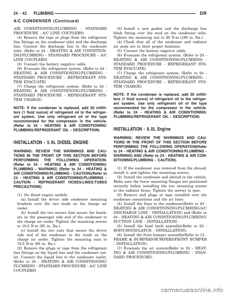
AIR CONDITIONING/PLUMBING - STANDARD
PROCEDURE - A/C LINE COUPLERS)
(4) Remove the tape or plugs from the refrigerant
line fittings on the condenser inlet and the discharge
line. Connect the discharge line to the condenser
inlet. (Refer to 24 - HEATING & AIR CONDITION-
ING/PLUMBING - STANDARD PROCEDURE - A/C
LINE COUPLERS)
(5) Connect the battery negative cable.
(6) Evacuate the refrigerant system. (Refer to 24 -
HEATING & AIR CONDITIONING/PLUMBING -
STANDARD PROCEDURE - REFRIGERANT SYS-
TEM EVACUATE)
(7) Charge the refrigerant system. (Refer to 24 -
HEATING & AIR CONDITIONING/PLUMBING -
STANDARD PROCEDURE - REFRIGERANT SYS-
TEM CHARGE)
NOTE: If the condenser is replaced, add 30 millili-
ters (1 fluid ounce) of refrigerant oil to the refriger-
ant system. Use only refrigerant oil of the type
recommended for the compressor in the vehicle.
(Refer to 24 - HEATING & AIR CONDITIONING/
PLUMBING/REFRIGERANT OIL - DESCRIPTION)
INSTALLATION - 5.9L DIESEL ENGINE
WARNING: REVIEW THE WARNINGS AND CAU-
TIONS IN THE FRONT OF THIS SECTION BEFORE
PERFORMING THE FOLLOWING OPERATION.
(Refer to 24 - HEATING & AIR CONDITIONING/
PLUMBING - WARNING) (Refer to 24 - HEATING &
AIR CONDITIONING/PLUMBING - CAUTION)(Refer to
24 - HEATING & AIR CONDITIONING/PLUMBING -
CAUTION - REFRIGERANT HOSES/LINES/TUBES
PRECAUTIONS)
(1) On diesel engine models:
(a) Install the driver side condenser mounting
brackets over the two studs on the charge air
cooler.
(b) Install the two screws that secure the brack-
ets on the passenger side end of the condenser to
the charge air cooler. Tighten the mounting screws
to 10.5 N´m (95 in. lbs.).
(c) Install the two nuts that secure the driver
side end of the condenser to the studs on the
charge air cooler. Tighten the mounting nuts to
10.5 N´m (95 in. lbs.).
(2) Remove the plugs or tape from the refrigerant
line fittings on the liquid line and the condenser out-
let. Connect the liquid line to the condenser outlet.
(Refer to 24 - HEATING & AIR CONDITIONING/
PLUMBING - STANDARD PROCEDURE - A/C LINE
COUPLERS)(3) Install a new gasket and the discharge line
block fitting over the stud on the condenser inlet.
Tighten the mounting nut to 20 N´m (180 in. lbs.).
(4) Check that all of the condenser and radiator
air seals are in their proper locations.
(5) Connect the battery negative cable.
(6) Evacuate the refrigerant system. (Refer to 24 -
HEATING & AIR CONDITIONING/PLUMBING -
STANDARD PROCEDURE - REFRIGERANT SYS-
TEM EVACUATE)
(7) Charge the refrigerant system. (Refer to 24 -
HEATING & AIR CONDITIONING/PLUMBING -
STANDARD PROCEDURE - REFRIGERANT SYS-
TEM CHARGE)
NOTE: If the condenser is replaced, add 30 millili-
ters (1 fluid ounce) of refrigerant oil to the refriger-
ant system. Use only refrigerant oil of the type
recommended for the compressor in the vehicle.
(Refer to 24 - HEATING & AIR CONDITIONING/
PLUMBING/REFRIGERANT OIL - DESCRIPTION)
INSTALLATION - 8.0L Engine
WARNING: REVIEW THE WARNINGS AND CAU-
TIONS IN THE FRONT OF THIS SECTION BEFORE
PERFORMING THE FOLLOWING OPERATION(Refer
to 24 - HEATING & AIR CONDITIONING/PLUMBING -
WARNING) AND (Refer to 24 - HEATING & AIR CON-
DITIONING/PLUMBING - CAUTION).
(1) If the condenser was removed from the shroud,
install it and tighten the mounting screws.
(2) Install the condenser and shroud in the vehicle.
Make sure the lower mounting flanges are positioned
correctly before installing the two mounting screws
to the radiator brace. Tighten the screws to spec.
(3) Remove and plugs or tape installed over the
condenser connections and the a/c lines.
(4) Install the lines to the condenser(Refer to 24 -
HEATING & AIR CONDITIONING/PLUMBING/A/C
DISCHARGE LINE - INSTALLATION) and (Refer to
24 - HEATING & AIR CONDITIONING/PLUMBING/
SUCTION LINE - INSTALLATION).
(5) Install the hood latch assembly(Refer to 23 -
BODY/HOOD/LATCH - INSTALLATION).
(6) Install the front bumper assembly(Refer to 13 -
FRAME & BUMPERS/BUMPERS/FRONT BUMPER
- INSTALLATION).
(7) Evacuate the a/c system(Refer to 24 - HEAT-
ING & AIR CONDITIONING/PLUMBING - STAN-
DARD PROCEDURE).
24 - 42 PLUMBINGDR
A/C CONDENSER (Continued)
Page 2830 of 2895
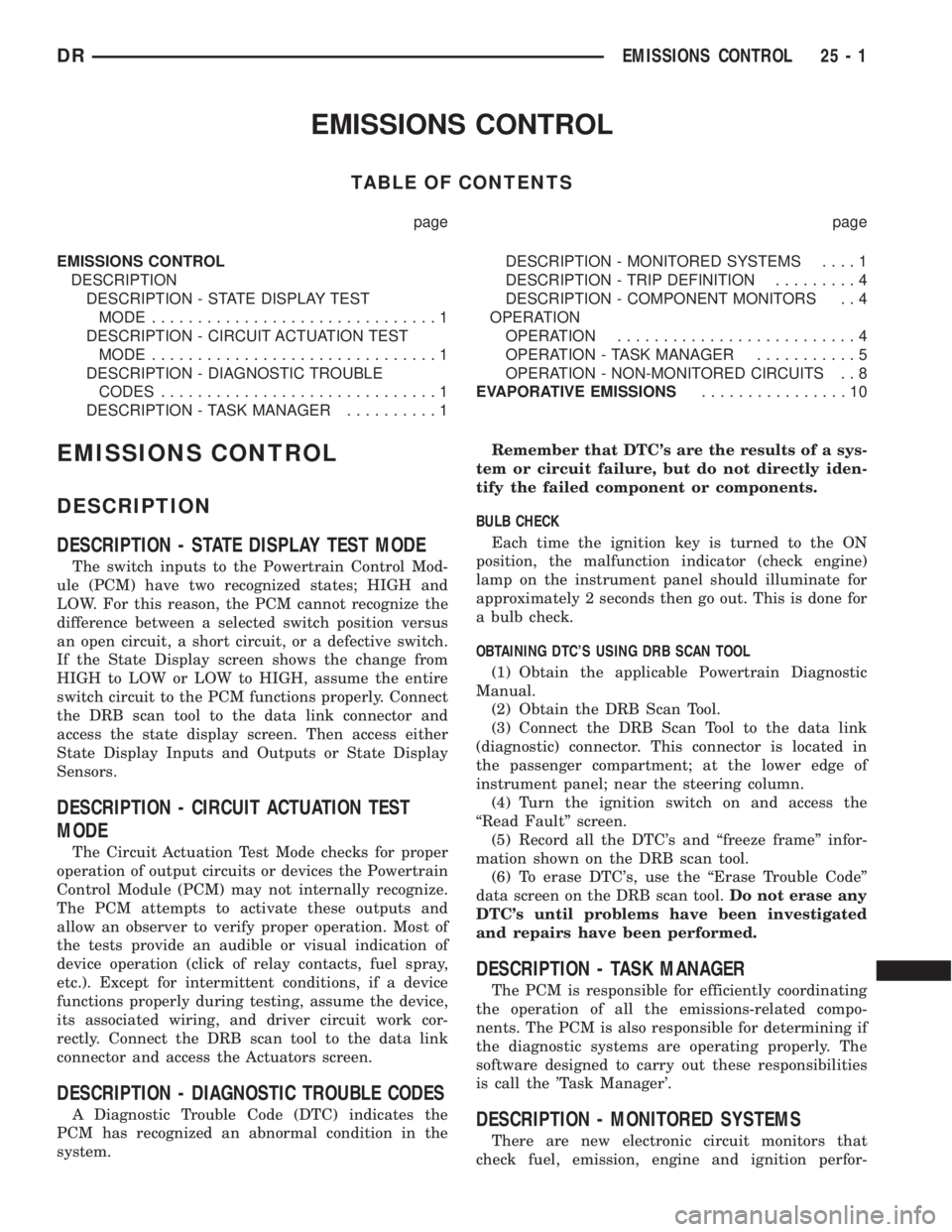
EMISSIONS CONTROL
TABLE OF CONTENTS
page page
EMISSIONS CONTROL
DESCRIPTION
DESCRIPTION - STATE DISPLAY TEST
MODE...............................1
DESCRIPTION - CIRCUIT ACTUATION TEST
MODE...............................1
DESCRIPTION - DIAGNOSTIC TROUBLE
CODES..............................1
DESCRIPTION - TASK MANAGER..........1DESCRIPTION - MONITORED SYSTEMS....1
DESCRIPTION - TRIP DEFINITION.........4
DESCRIPTION - COMPONENT MONITORS . . 4
OPERATION
OPERATION..........................4
OPERATION - TASK MANAGER...........5
OPERATION - NON-MONITORED CIRCUITS . . 8
EVAPORATIVE EMISSIONS................10
EMISSIONS CONTROL
DESCRIPTION
DESCRIPTION - STATE DISPLAY TEST MODE
The switch inputs to the Powertrain Control Mod-
ule (PCM) have two recognized states; HIGH and
LOW. For this reason, the PCM cannot recognize the
difference between a selected switch position versus
an open circuit, a short circuit, or a defective switch.
If the State Display screen shows the change from
HIGH to LOW or LOW to HIGH, assume the entire
switch circuit to the PCM functions properly. Connect
the DRB scan tool to the data link connector and
access the state display screen. Then access either
State Display Inputs and Outputs or State Display
Sensors.
DESCRIPTION - CIRCUIT ACTUATION TEST
MODE
The Circuit Actuation Test Mode checks for proper
operation of output circuits or devices the Powertrain
Control Module (PCM) may not internally recognize.
The PCM attempts to activate these outputs and
allow an observer to verify proper operation. Most of
the tests provide an audible or visual indication of
device operation (click of relay contacts, fuel spray,
etc.). Except for intermittent conditions, if a device
functions properly during testing, assume the device,
its associated wiring, and driver circuit work cor-
rectly. Connect the DRB scan tool to the data link
connector and access the Actuators screen.
DESCRIPTION - DIAGNOSTIC TROUBLE CODES
A Diagnostic Trouble Code (DTC) indicates the
PCM has recognized an abnormal condition in the
system.Remember that DTC's are the results of a sys-
tem or circuit failure, but do not directly iden-
tify the failed component or components.
BULB CHECK
Each time the ignition key is turned to the ON
position, the malfunction indicator (check engine)
lamp on the instrument panel should illuminate for
approximately 2 seconds then go out. This is done for
a bulb check.
OBTAINING DTC'S USING DRB SCAN TOOL
(1) Obtain the applicable Powertrain Diagnostic
Manual.
(2) Obtain the DRB Scan Tool.
(3) Connect the DRB Scan Tool to the data link
(diagnostic) connector. This connector is located in
the passenger compartment; at the lower edge of
instrument panel; near the steering column.
(4) Turn the ignition switch on and access the
ªRead Faultº screen.
(5) Record all the DTC's and ªfreeze frameº infor-
mation shown on the DRB scan tool.
(6) To erase DTC's, use the ªErase Trouble Codeº
data screen on the DRB scan tool.Do not erase any
DTC's until problems have been investigated
and repairs have been performed.
DESCRIPTION - TASK MANAGER
The PCM is responsible for efficiently coordinating
the operation of all the emissions-related compo-
nents. The PCM is also responsible for determining if
the diagnostic systems are operating properly. The
software designed to carry out these responsibilities
is call the 'Task Manager'.
DESCRIPTION - MONITORED SYSTEMS
There are new electronic circuit monitors that
check fuel, emission, engine and ignition perfor-
DREMISSIONS CONTROL 25 - 1
Page 2834 of 2895
problem is repaired or ceases to exist, the PCM can-
cels the code after 40 warm-up cycles. Diagnostic
trouble codes that affect vehicle emissions illuminate
the Malfunction Indicator Lamp (MIL). The MIL is
displayed as an engine icon (graphic) on the instru-
ment panel. Refer to Malfunction Indicator Lamp in
this section.
Certain criteria must be met before the PCM
stores a DTC in memory. The criteria may be a spe-
cific range of engine RPM, engine temperature,
and/or input voltage to the PCM.
The PCM might not store a DTC for a monitored
circuit even though a malfunction has occurred. This
may happen because one of the DTC criteria for the
circuit has not been met.For example,assume the
diagnostic trouble code criteria requires the PCM to
monitor the circuit only when the engine operates
between 750 and 2000 RPM. Suppose the sensor's
output circuit shorts to ground when engine operates
above 2400 RPM (resulting in 0 volt input to the
PCM). Because the condition happens at an engine
speed above the maximum threshold (2000 rpm), the
PCM will not store a DTC.
There are several operating conditions for which
the PCM monitors and sets DTC's. Refer to Moni-
tored Systems, Components, and Non-Monitored Cir-
cuits in this section.
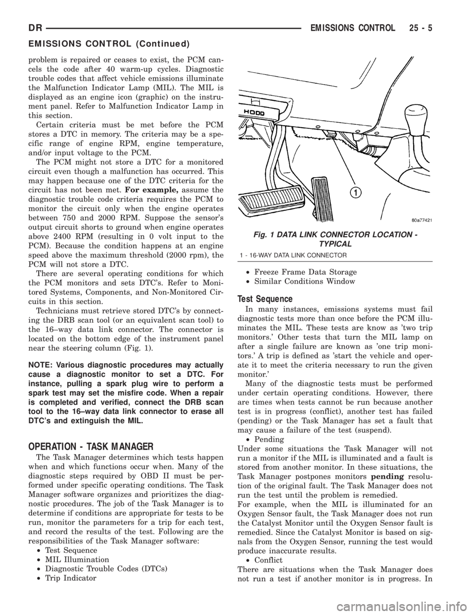
Technicians must retrieve stored DTC's by connect-
ing the DRB scan tool (or an equivalent scan tool) to
the 16±way data link connector. The connector is
located on the bottom edge of the instrument panel
near the steering column (Fig. 1).
NOTE: Various diagnostic procedures may actually
cause a diagnostic monitor to set a DTC. For
instance, pulling a spark plug wire to perform a
spark test may set the misfire code. When a repair
is completed and verified, connect the DRB scan
tool to the 16±way data link connector to erase all
DTC's and extinguish the MIL.
OPERATION - TASK MANAGER
The Task Manager determines which tests happen
when and which functions occur when. Many of the
diagnostic steps required by OBD II must be per-
formed under specific operating conditions. The Task
Manager software organizes and prioritizes the diag-
nostic procedures. The job of the Task Manager is to
determine if conditions are appropriate for tests to be
run, monitor the parameters for a trip for each test,
and record the results of the test. Following are the
responsibilities of the Task Manager software:
²Test Sequence
²MIL Illumination
²Diagnostic Trouble Codes (DTCs)
²Trip Indicator²Freeze Frame Data Storage
²Similar Conditions Window
Test Sequence
In many instances, emissions systems must fail
diagnostic tests more than once before the PCM illu-
minates the MIL. These tests are know as 'two trip
monitors.' Other tests that turn the MIL lamp on
after a single failure are known as 'one trip moni-
tors.' A trip is defined as 'start the vehicle and oper-
ate it to meet the criteria necessary to run the given
monitor.'
Many of the diagnostic tests must be performed
under certain operating conditions. However, there
are times when tests cannot be run because another
test is in progress (conflict), another test has failed
(pending) or the Task Manager has set a fault that
may cause a failure of the test (suspend).
²Pending
Under some situations the Task Manager will not
run a monitor if the MIL is illuminated and a fault is
stored from another monitor. In these situations, the
Task Manager postpones monitorspendingresolu-
tion of the original fault. The Task Manager does not
run the test until the problem is remedied.
For example, when the MIL is illuminated for an
Oxygen Sensor fault, the Task Manager does not run
the Catalyst Monitor until the Oxygen Sensor fault is
remedied. Since the Catalyst Monitor is based on sig-
nals from the Oxygen Sensor, running the test would
produce inaccurate results.
²Conflict
There are situations when the Task Manager does
not run a test if another monitor is in progress. In
Fig. 1 DATA LINK CONNECTOR LOCATION -
TYPICAL
1 - 16-WAY DATA LINK CONNECTOR
DREMISSIONS CONTROL 25 - 5
EMISSIONS CONTROL (Continued)
Page 2835 of 2895
these situations, the effects of another monitor run-
ning could result in an erroneous failure. If thiscon-
flictis present, the monitor is not run until the
conflicting condition passes. Most likely the monitor
will run later after the conflicting monitor has
passed.
For example, if the Fuel System Monitor is in
progress, the Task Manager does not run the EGR
Monitor. Since both tests monitor changes in air/fuel
ratio and adaptive fuel compensation, the monitors
will conflict with each other.
²Suspend
Occasionally the Task Manager may not allow a two
trip fault to mature. The Task Manager willsus-
pendthe maturing of a fault if a condition exists
that may induce an erroneous failure. This prevents
illuminating the MIL for the wrong fault and allows
more precis diagnosis.
For example, if the PCM is storing a one trip fault
for the Oxygen Sensor and the EGR monitor, the
Task Manager may still run the EGR Monitor but
will suspend the results until the Oxygen Sensor
Monitor either passes or fails. At that point the Task
Manager can determine if the EGR system is actu-
ally failing or if an Oxygen Sensor is failing.
MIL Illumination
The PCM Task Manager carries out the illumina-
tion of the MIL. The Task Manager triggers MIL illu-
mination upon test failure, depending on monitor
failure criteria.
The Task Manager Screen shows both a Requested
MIL state and an Actual MIL state. When the MIL is
illuminated upon completion of a test for a third trip,
the Requested MIL state changes to OFF. However,
the MIL remains illuminated until the next key
cycle. (On some vehicles, the MIL will actually turn
OFF during the third key cycle) During the key cycle
for the third good trip, the Requested MIL state is
OFF, while the Actual MILL state is ON. After the
next key cycle, the MIL is not illuminated and both
MIL states read OFF.
Diagnostic Trouble Codes (DTCs)
With OBD II, different DTC faults have different
priorities according to regulations. As a result, the
priorities determine MIL illumination and DTC era-
sure. DTCs are entered according to individual prior-
ity. DTCs with a higher priority overwrite lower
priority DTCs.
Priorities
²Priority 0 ÐNon-emissions related trouble codes
²Priority 1 Ð One trip failure of a two trip fault
for non-fuel system and non-misfire.²Priority 2 Ð One trip failure of a two trip fault
for fuel system (rich/lean) or misfire.
²Priority3ÐTwotrip failure for a non-fuel sys-
tem and non-misfire or matured one trip comprehen-
sive component fault.
²Priority4ÐTwotrip failure or matured fault
for fuel system (rich/lean) and misfire or one trip cat-
alyst damaging misfire.
Non-emissions related failures have no priority.
One trip failures of two trip faults have low priority.
Two trip failures or matured faults have higher pri-
ority. One and two trip failures of fuel system and
misfire monitor take precedence over non-fuel system
and non-misfire failures.
DTC Self Erasure
With one trip components or systems, the MIL is
illuminated upon test failure and DTCs are stored.
Two trip monitors are components requiring failure
in two consecutive trips for MIL illumination. Upon
failure of the first test, the Task Manager enters a
maturing code. If the component fails the test for a
second time the code matures and a DTC is set.
After three good trips the MIL is extinguished and
the Task Manager automatically switches the trip
counter to a warm-up cycle counter. DTCs are auto-
matically erased following 40 warm-up cycles if the
component does not fail again.
For misfire and fuel system monitors, the compo-
nent must pass the test under a Similar Conditions
Window in order to record a good trip. A Similar Con-
ditions Window is when engine RPM is within 375
RPM and load is within 10% of when the fault
occurred.
NOTE: It is important to understand that a compo-
nent does not have to fail under a similar window of
operation to mature. It must pass the test under a
Similar Conditions Window when it failed to record
a Good Trip for DTC erasure for misfire and fuel
system monitors.
DTCs can be erased anytime with a DRB III. Eras-
ing the DTC with the DRB III erases all OBD II
information. The DRB III automatically displays a
warning that erasing the DTC will also erase all
OBD II monitor data. This includes all counter infor-
mation for warm-up cycles, trips and Freeze Frame.
Trip Indicator
TheTripis essential for running monitors and
extinguishing the MIL. In OBD II terms, a trip is a
set of vehicle operating conditions that must be met
for a specific monitor to run. All trips begin with a
key cycle.
Good Trip
The Good Trip counters are as follows:
25 - 6 EMISSIONS CONTROLDR
EMISSIONS CONTROL (Continued)
Page 2836 of 2895
²Specific Good Trip
²Fuel System Good Trip
²Misfire Good Trip
²Alternate Good Trip (appears as a Global Good
Trip on DRB III)
²Comprehensive Components
²Major Monitor
²Warm-Up Cycles
Specific Good Trip
The term Good Trip has different meanings
depending on the circumstances:
²If the MIL is OFF, a trip is defined as when the
Oxygen Sensor Monitor and the Catalyst Monitor
have been completed in the same drive cycle.
²If the MIL is ON and a DTC was set by the Fuel
Monitor or Misfire Monitor (both continuous moni-
tors), the vehicle must be operated in the Similar
Condition Window for a specified amount of time.
²If the MIL is ON and a DTC was set by a Task
Manager commanded once-per-trip monitor (such as
the Oxygen Sensor Monitor, Catalyst Monitor, Purge
Flow Monitor, Leak Detection Pump Monitor, EGR
Monitor or Oxygen Sensor Heater Monitor), a good
trip is when the monitor is passed on the next start-
up.
²If the MIL is ON and any other emissions DTC
was set (not an OBD II monitor), a good trip occurs
when the Oxygen Sensor Monitor and Catalyst Mon-
itor have been completed, or two minutes of engine
run time if the Oxygen Sensor Monitor and Catalyst
Monitor have been stopped from running.
Fuel System Good Trip
To count a good trip (three required) and turn off
the MIL, the following conditions must occur:
²Engine in closed loop
²Operating in Similar Conditions Window
²Short Term multiplied by Long Term less than
threshold
²Less than threshold for a predetermined time
If all of the previous criteria are met, the PCM will
count a good trip (three required) and turn off the
MIL.
Misfire Good Trip
If the following conditions are met the PCM will
count one good trip (three required) in order to turn
off the MIL:
²Operating in Similar Condition Window
²1000 engine revolutions with no misfire
Warm-Up Cycles
Once the MIL has been extinguished by the Good
Trip Counter, the PCM automatically switches to a
Warm-Up Cycle Counter that can be viewed on the
DRB III. Warm-Up Cycles are used to erase DTCs
and Freeze Frames. Forty Warm-Up cycles must
occur in order for the PCM to self-erase a DTC andFreeze Frame. A Warm-Up Cycle is defined as fol-
lows:
²Engine coolant temperature must start below
and rise above 160É F
²Engine coolant temperature must rise by 40É F
²No further faults occur
Freeze Frame Data Storage
Once a failure occurs, the Task Manager records
several engine operating conditions and stores it in a
Freeze Frame. The Freeze Frame is considered one
frame of information taken by an on-board data
recorder. When a fault occurs, the PCM stores the
input data from various sensors so that technicians
can determine under what vehicle operating condi-
tions the failure occurred.
The data stored in Freeze Frame is usually
recorded when a system fails the first time for two
trip faults. Freeze Frame data will only be overwrit-
ten by a different fault with a higher priority.
CAUTION: Erasing DTCs, either with the DRB III or
by disconnecting the battery, also clears all Freeze
Frame data.
Similar Conditions Window
The Similar Conditions Window displays informa-
tion about engine operation during a monitor. Abso-
lute MAP (engine load) and Engine RPM are stored
in this window when a failure occurs. There are two
different Similar conditions Windows: Fuel System
and Misfire.
FUEL SYSTEM
²Fuel System Similar Conditions WindowÐ
An indicator that 'Absolute MAP When Fuel Sys Fail'
and 'RPM When Fuel Sys Failed' are all in the same
range when the failure occurred. Indicated by switch-
ing from 'NO' to 'YES'.
²Absolute MAP When Fuel Sys FailÐ The
stored MAP reading at the time of failure. Informs
the user at what engine load the failure occurred.
²Absolute MAPÐ A live reading of engine load
to aid the user in accessing the Similar Conditions
Window.
²RPM When Fuel Sys FailÐ The stored RPM
reading at the time of failure. Informs the user at
what engine RPM the failure occurred.
²Engine RPMÐ A live reading of engine RPM
to aid the user in accessing the Similar Conditions
Window.
²Adaptive Memory FactorÐ The PCM utilizes
both Short Term Compensation and Long Term Adap-
tive to calculate the Adaptive Memory Factor for
total fuel correction.
DREMISSIONS CONTROL 25 - 7
EMISSIONS CONTROL (Continued)
Page 2841 of 2895

SPECIFICATIONS
TORQUE - EVAP SYSTEM
DESCRIPTION N´m Ft. Lbs. In. Lbs.
EVAP Canister Mounting
Nuts11 -95
EVAP Canister Mounting
Bracket-to-Frame Bolts14 10125
Leak Detection Pump
Mounting Bolts11 - 9 5
Leak Detection Pump
Filter Mounting Bolt11 - 9 5
CCV HOSE
DESCRIPTION - 8.0L V-10
The 8.0L V-10 engine is equipped with a Crankcase
Ventilation (CCV) system. The CCV system performs
the same function as a conventional PCV system, but
does not use a vacuum controlled valve (PCV valve).
A molded vacuum tube connects manifold vacuum
to the top of the right cylinder head (valve) cover.
The vacuum tube connects to a fixed orifice fitting
(Fig. 2) of a calibrated size 2.6 mm (0.10 inches).
OPERATION - 8.0L V-10
A molded vacuum tube connects manifold vacuum
to the top of the right cylinder head (valve) cover.
The vacuum tube connects to a fixed orifice fitting
(Fig. 2) of a calibrated size 2.6 mm (0.10 inches). Thefitting meters the amount of crankcase vapors drawn
out of the engine.The fixed orifice fitting is grey
in color.A similar fitting (but does not contain a
fixed orifice) is used on the left cylinder head (valve)
cover. This fitting is black in color. Do not inter-
change these two fittings.
When the engine is operating, fresh air enters the
engine and mixes with crankcase vapors. Manifold
vacuum draws the vapor/air mixture through the
fixed orifice and into the intake manifold. The vapors
are then consumed during engine combustion.
EVAP/PURGE SOLENOID
DESCRIPTION
The duty cycle EVAP canister purge solenoid is
located in the engine compartment. It is attached to
the side of the Power Distribution Center (PDC).
OPERATION
The Powertrain Control Module (PCM) operates
the solenoid.
During the cold start warm-up period and the hot
start time delay, the PCM does not energize the sole-
noid. When de-energized, no vapors are purged. The
PCM de-energizes the solenoid during open loop oper-
ation.
The engine enters closed loop operation after it
reaches a specified temperature and the time delay
ends. During closed loop operation, the PCM ener-
gizes and de-energizes the solenoid 5 or 10 times per
second, depending upon operating conditions. The
PCM varies the vapor flow rate by changing solenoid
pulse width. Pulse width is the amount of time the
solenoid energizes. The PCM adjusts solenoid pulse
width based on engine operating condition.
Fig. 2 FIXED ORIFICE FITTING - 8.0L V-10 ENGINE -
TYPICAL
1 - VACUUM TUBE
2 - FIXED ORIFICE FITTING
3 - COIL PACKS
4 - ORIFICE FITTING HOSE CONNECTIONS
25 - 12 EVAPORATIVE EMISSIONSDR
EVAPORATIVE EMISSIONS (Continued)