2003 DODGE RAM transmission
[x] Cancel search: transmissionPage 612 of 2895

On models equipped with optional side curtain air-
bags, the ACM communicates with both the left and
right Side Impact Airbag Control Modules (SIACM)
over the PCI data bus. The SIACM notifies the ACM
when it has detected a monitored system fault and
stored a DTC in memory for its respective side cur-
tain airbag system, and the ACM sets a DTC and
controls the airbag indicator operation accordingly.
The ACM receives battery current through two cir-
cuits; a fused ignition switch output (run) circuit
through a fuse in the Integrated Power Module
(IPM), and a fused ignition switch output (run-start)
circuit through a second fuse in the IPM. The ACM
receives ground through a ground circuit and take
out of the instrument panel wire harness. This take
out has a single eyelet terminal connector that is
secured by a ground screw to the instrument panel
support structure. These connections allow the ACM
to be operational whenever the ignition switch is in
the Start or On positions. The ACM also contains an
energy-storage capacitor. When the ignition switch is
in the Start or On positions, this capacitor is contin-
ually being charged with enough electrical energy to
deploy the front supplemental restraint components
for up to one second following a battery disconnect or
failure. The purpose of the capacitor is to provide
backup supplemental restraint system protection in
case there is a loss of battery current supply to the
ACM during an impact.
Two sensors are contained within the ACM; an
electronic impact sensor, and a safing sensor. The
electronic impact sensor is an accelerometer that
senses the rate of vehicle deceleration, which pro-
vides verification of the direction and severity of an
impact. The safing sensor is an electromechanical
sensor within the ACM that provides an additional
logic input to the ACM microprocessor. The safing
sensor is a normally open switch that is used to ver-
ify the need for a front supplemental restraint
deployment by detecting impact energy of a lesser
magnitude than that of the electronic impact sensor,
and must be closed in order for the front airbags or
seat belt tensioners to deploy. A pre-programmed
decision algorithm in the ACM microprocessor deter-
mines when the deceleration rate as signaled by the
impact sensor and the safing sensor indicate an
impact that is severe enough to require front supple-
mental restraint system protection and, based upon
the status of the passenger airbag on/off switch input
and the severity of the monitored impact, determines
what combination of seat belt tensioner and front air-
bag deployment is required for each front seating
position. When the programmed conditions are met,
the ACM sends the proper electrical signals to deploy
the seat belt tensioners and dual front airbags.The hard wired inputs and outputs for the ACM
may be diagnosed and tested using conventional
diagnostic tools and procedures. However, conven-
tional diagnostic methods will not prove conclusive in
the diagnosis of the ACM, the PCI data bus network,
or the electronic message inputs to and outputs from
the ACM. The most reliable, efficient, and accurate
means to diagnose the ACM, the PCI data bus net-
work, and the electronic message inputs to and out-
puts from the ACM requires the use of a DRBIIIt
scan tool. Refer to the appropriate diagnostic infor-
mation.
REMOVAL
WARNING: ON VEHICLES EQUIPPED WITH AIR-
BAGS, DISABLE THE SUPPLEMENTAL RESTRAINT
SYSTEM BEFORE ATTEMPTING ANY STEERING
WHEEL, STEERING COLUMN, DRIVER AIRBAG,
PASSENGER AIRBAG, SEAT BELT TENSIONER,
SIDE CURTAIN AIRBAG, OR INSTRUMENT PANEL
COMPONENT DIAGNOSIS OR SERVICE. DISCON-
NECT AND ISOLATE THE BATTERY NEGATIVE
(GROUND) CABLE, THEN WAIT TWO MINUTES FOR
THE SYSTEM CAPACITOR TO DISCHARGE BEFORE
PERFORMING FURTHER DIAGNOSIS OR SERVICE.
THIS IS THE ONLY SURE WAY TO DISABLE THE
SUPPLEMENTAL RESTRAINT SYSTEM. FAILURE TO
TAKE THE PROPER PRECAUTIONS COULD
RESULT IN ACCIDENTAL AIRBAG DEPLOYMENT
AND POSSIBLE PERSONAL INJURY.
WARNING: THE AIRBAG CONTROL MODULE CON-
TAINS THE IMPACT SENSOR, WHICH ENABLES
THE SYSTEM TO DEPLOY THE FRONT SUPPLE-
MENTAL RESTRAINTS. NEVER STRIKE OR DROP
THE AIRBAG CONTROL MODULE, AS IT CAN DAM-
AGE THE IMPACT SENSOR OR AFFECT ITS CALI-
BRATION. IF AN AIRBAG CONTROL MODULE IS
ACCIDENTALLY DROPPED DURING SERVICE, THE
MODULE MUST BE SCRAPPED AND REPLACED
WITH A NEW UNIT. FAILURE TO OBSERVE THIS
WARNING COULD RESULT IN ACCIDENTAL,
INCOMPLETE, OR IMPROPER FRONT SUPPLEMEN-
TAL RESTRAINT DEPLOYMENT AND POSSIBLE
OCCUPANT INJURIES.
(1) Disconnect and isolate the battery negative
cable. Wait two minutes for the system capacitor to
discharge before further service.
(2) On models with a manual transmission,
remove the floor console from the top of the floor
panel transmission tunnel. (Refer to 23 - BODY/IN-
TERIOR/FLOOR CONSOLE - REMOVAL).
(3) On models with an automatic transmission,
remove the ACM cover from the instrument panel.
DRRESTRAINTS 8O - 11
AIRBAG CONTROL MODULE (Continued)
Page 613 of 2895

(Refer to 8 - ELECTRICAL/RESTRAINTS/ACM
COVER - REMOVAL).
(4) Reach through the rearward facing opening
below the instrument panel center stack support
bracket on the top of the floor panel transmission
tunnel to access and disconnect the instrument panel
wire harness connector for the Airbag Control Mod-
ule (ACM) from the ACM connector receptacle located
on the rearward facing side of the module (Fig. 8). To
disconnect the instrument panel wire harness con-
nector from the ACM:
(a) Slide the red Connector Position Assurance
(CPA) lock on the top of the connector toward the
side of the connector.
(b) Depress the connector latch tab and pull the
connector straight away from the ACM connector
receptacle.
(5) From the right side of the floor panel transmis-
sion tunnel, loosen each of the two screws that secure
the right side of the ACM to the bracket on the floor
panel transmission tunnel about 7 millimeters (0.25
inch).
(6) From the left side of the floor panel transmis-
sion tunnel, remove the two screws that secure the
left side of the ACM to the bracket on the floor panel
transmission tunnel.(7) Still working from the left side of the floor
panel transmission tunnel, lift the ACM upward far
enough to disengage the locating pins on the bottom
of the ACM mounting flanges from the locating holes
in the mounting bracket, then slide the ACM toward
the left far enough to disengage the slotted holes in
the right ACM mounting flanges from under the
heads of the two previously loosened right mounting
screws.
(8) Remove the ACM from the left side of the floor
panel transmission tunnel.
INSTALLATION
WARNING: ON VEHICLES EQUIPPED WITH AIR-
BAGS, DISABLE THE SUPPLEMENTAL RESTRAINT
SYSTEM BEFORE ATTEMPTING ANY STEERING
WHEEL, STEERING COLUMN, DRIVER AIRBAG,
PASSENGER AIRBAG, SEAT BELT TENSIONER,
SIDE CURTAIN AIRBAG, OR INSTRUMENT PANEL
COMPONENT DIAGNOSIS OR SERVICE. DISCON-
NECT AND ISOLATE THE BATTERY NEGATIVE
(GROUND) CABLE, THEN WAIT TWO MINUTES FOR
THE SYSTEM CAPACITOR TO DISCHARGE BEFORE
PERFORMING FURTHER DIAGNOSIS OR SERVICE.
THIS IS THE ONLY SURE WAY TO DISABLE THE
SUPPLEMENTAL RESTRAINT SYSTEM. FAILURE TO
TAKE THE PROPER PRECAUTIONS COULD
RESULT IN ACCIDENTAL AIRBAG DEPLOYMENT
AND POSSIBLE PERSONAL INJURY.
WARNING: THE AIRBAG CONTROL MODULE CON-
TAINS THE IMPACT SENSOR, WHICH ENABLES
THE SYSTEM TO DEPLOY THE FRONT SUPPLE-
MENTAL RESTRAINTS. NEVER STRIKE OR DROP
THE AIRBAG CONTROL MODULE, AS IT CAN DAM-
AGE THE IMPACT SENSOR OR AFFECT ITS CALI-
BRATION. IF AN AIRBAG CONTROL MODULE IS
ACCIDENTALLY DROPPED DURING SERVICE, THE
MODULE MUST BE SCRAPPED AND REPLACED
WITH A NEW UNIT. FAILURE TO OBSERVE THIS
WARNING COULD RESULT IN ACCIDENTAL,
INCOMPLETE, OR IMPROPER FRONT SUPPLEMEN-
TAL RESTRAINT DEPLOYMENT AND POSSIBLE
OCCUPANT INJURIES.
(1) Position the Airbag Control Module (ACM) to
the left side of the floor panel transmission tunnel
near the ACM bracket (Fig. 8). When the ACM is cor-
rectly positioned, the arrow on the ACM housing will
be pointed forward in the vehicle.
(2) From the left side of the floor panel transmis-
sion tunnel, slide the ACM toward the right far
enough to engage the slotted holes in the right ACM
mounting flanges under the heads of the two previ-
ously loosened right mounting screws, then engage
Fig. 8 Airbag Control Module Remove/Install
1 - WIRE HARNESS CONNECTOR
2 - AIRBAG CONTROL MODULE
3 - SCREW (4)
4 - FLOOR PANEL TRANSMISSION TUNNEL
8O - 12 RESTRAINTSDR
AIRBAG CONTROL MODULE (Continued)
Page 614 of 2895
the locating pins on the bottom of the ACM mounting
flanges into the locating holes in the bracket.
(3) Still working from the left side of the floor
panel transmission tunnel, install and tighten the
two screws that secure the left ACM mounting
flanges to the bracket that is welded onto the floor
panel transmission tunnel. Tighten the screws to 14
N´m (10 ft. lbs.).
(4) From the right side of the floor panel transmis-
sion tunnel, tighten each of the two screws that
secure the right side of the ACM to the bracket on
the floor panel transmission tunnel. Tighten the
screws to 14 N´m (10 ft. lbs.).
(5) Reach through the rearward facing opening
below the instrument panel center stack support
bracket on the top of the floor panel transmission
tunnel to access and reconnect the instrument panel
wire harness connector for the ACM to the ACM con-
nector receptacle located on the rearward facing side
of the module. Be certain that the latch and the red
Connector Position Assurance (CPA) lock on the con-
nector are each fully engaged.
(6) On models with an automatic transmission,
reinstall the ACM cover onto the instrument panel.
(Refer to 8 - ELECTRICAL/RESTRAINTS/ACM
COVER - INSTALLATION).
(7) On models with a manual transmission, rein-
stall the floor console onto the top of the floor panel
transmission tunnel. (Refer to 23 - BODY/INTERI-
OR/FLOOR CONSOLE - INSTALLATION).
(8) Do not reconnect the battery negative cable at
this time. The supplemental restraint system verifi-
cation test procedure should be performed following
service of any supplemental restraint system compo-
nent. (Refer to 8 - ELECTRICAL/RESTRAINTS -
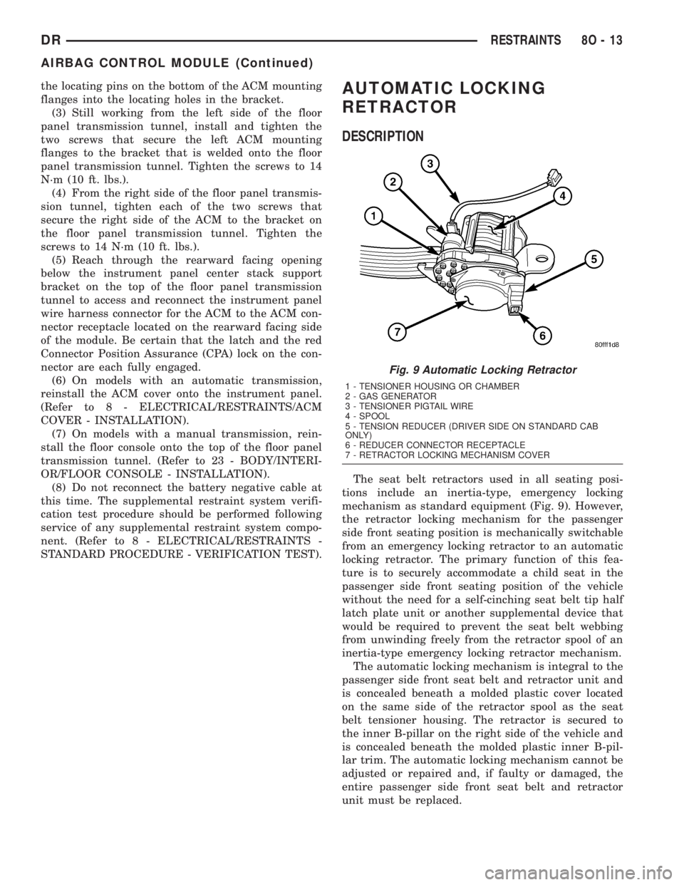
STANDARD PROCEDURE - VERIFICATION TEST).AUTOMATIC LOCKING
RETRACTOR
DESCRIPTION
The seat belt retractors used in all seating posi-
tions include an inertia-type, emergency locking
mechanism as standard equipment (Fig. 9). However,
the retractor locking mechanism for the passenger
side front seating position is mechanically switchable
from an emergency locking retractor to an automatic
locking retractor. The primary function of this fea-
ture is to securely accommodate a child seat in the
passenger side front seating position of the vehicle
without the need for a self-cinching seat belt tip half
latch plate unit or another supplemental device that
would be required to prevent the seat belt webbing
from unwinding freely from the retractor spool of an
inertia-type emergency locking retractor mechanism.
The automatic locking mechanism is integral to the
passenger side front seat belt and retractor unit and
is concealed beneath a molded plastic cover located
on the same side of the retractor spool as the seat
belt tensioner housing. The retractor is secured to
the inner B-pillar on the right side of the vehicle and
is concealed beneath the molded plastic inner B-pil-
lar trim. The automatic locking mechanism cannot be
adjusted or repaired and, if faulty or damaged, the
entire passenger side front seat belt and retractor
unit must be replaced.
Fig. 9 Automatic Locking Retractor
1 - TENSIONER HOUSING OR CHAMBER
2 - GAS GENERATOR
3 - TENSIONER PIGTAIL WIRE
4 - SPOOL
5 - TENSION REDUCER (DRIVER SIDE ON STANDARD CAB
ONLY)
6 - REDUCER CONNECTOR RECEPTACLE
7 - RETRACTOR LOCKING MECHANISM COVER
DRRESTRAINTS 8O - 13
AIRBAG CONTROL MODULE (Continued)
Page 622 of 2895
INSTALLATION
The clockspring cannot be repaired. It must be
replaced if faulty or damaged, or if the driver airbag
has been deployed.
If the clockspring is not properly centered in rela-
tion to the steering wheel, steering shaft and steer-
ing gear, it may be damaged. (Refer to 8 -
ELECTRICAL/RESTRAINTS/CLOCKSPRING -
STANDARD PROCEDURE - CLOCKSPRING CEN-
TERING). Service replacement clocksprings are
shipped pre-centered, with a plastic locking pin
installed. This locking pin should not be removed
until the clockspring has been installed on the steer-
ing column. If the locking pin is removed before the
clockspring is installed on a steering column, the
clockspring centering procedure must be performed.
WARNING: ON VEHICLES EQUIPPED WITH AIR-
BAGS, DISABLE THE SUPPLEMENTAL RESTRAINT
SYSTEM BEFORE ATTEMPTING ANY STEERING
WHEEL, STEERING COLUMN, DRIVER AIRBAG,
PASSENGER AIRBAG, SEAT BELT TENSIONER,
SIDE CURTAIN AIRBAG, OR INSTRUMENT PANEL
COMPONENT DIAGNOSIS OR SERVICE. DISCON-
NECT AND ISOLATE THE BATTERY NEGATIVE
(GROUND) CABLE, THEN WAIT TWO MINUTES FOR
THE SYSTEM CAPACITOR TO DISCHARGE BEFORE
PERFORMING FURTHER DIAGNOSIS OR SERVICE.THIS IS THE ONLY SURE WAY TO DISABLE THE
SUPPLEMENTAL RESTRAINT SYSTEM. FAILURE TO
TAKE THE PROPER PRECAUTIONS COULD
RESULT IN ACCIDENTAL AIRBAG DEPLOYMENT
AND POSSIBLE PERSONAL INJURY.
NOTE: Before starting this procedure, be certain
that the front wheels are still in the straight-ahead
position.
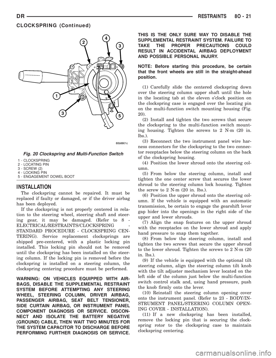
(1) Carefully slide the centered clockspring down
over the steering column upper shaft until the hole
in the locating tab at the eleven o'clock position on
the clockspring case is engaged over the locating pin
on the multi-function switch mounting housing (Fig.
20).
(2) Install and tighten the two screws that secure
the clockspring to the multi-function switch mount-
ing housing. Tighten the screws to 2 N´m (20 in.
lbs.).
(3) Reconnect the two instrument panel wire har-
ness connectors for the clockspring to the two connec-
tor receptacles below the steering column on the back
of the clockspring housing.
(4) Position the lower shroud onto the steering col-
umn.
(5) From below the steering column, install and
tighten the one center screw that secures the lower
shroud to the steering column lock housing. Tighten
the screw to 2 N´m (20 in. lbs.).
(6) Position the upper shroud onto the steering col-
umn. If the vehicle is equipped with an automatic
transmission, be certain to engage the gearshift lever
gap hider into the openings in the right side of the
upper and lower shrouds.
(7) Align the snap features on the upper shroud
with the receptacles on the lower shroud and apply
hand pressure to snap them together.
(8) From below the steering column, install and
tighten the two screws that secure the upper shroud
to the lower shroud. Tighten the screws to 2 N´m (20
in. lbs.).
(9) If the vehicle is equipped with the optional tilt
steering column, align the steering column tilt knob
with the tilt adjuster mechanism lever located on the
left side of the column just below the multi-function
switch control stalk and, using hand pressure, push
the knob firmly onto the lever.
(10) Reinstall the steering column opening cover
onto the instrument panel. (Refer to 23 - BODY/IN-
STRUMENT PANEL/STEERING COLUMN OPEN-
ING COVER - INSTALLATION).
(11) If a new clockspring has been installed,
remove the locking pin that is securing the clock-
spring rotor to the clockspring case to maintain
clockspring centering.
Fig. 20 Clockspring and Multi-Function Switch
1 - CLOCKSPRING
2 - LOCATING PIN
3 - SCREW (2)
4 - LOCKING PIN
5 - ENGAGEMENT DOWEL BOOT
DRRESTRAINTS 8O - 21
CLOCKSPRING (Continued)
Page 660 of 2895
SPEED CONTROL
TABLE OF CONTENTS
page page
SPEED CONTROL
DESCRIPTION..........................1
OPERATION............................2
DIAGNOSIS AND TESTING
DIAGNOSIS AND TESTING - VACUUM
SUPPLY TEST.........................2
DIAGNOSIS AND TESTING - ROAD TEST....3
SPECIFICATIONS
TORQUE - SPEED CONTROL.............3
CABLE
DESCRIPTION..........................3
OPERATION............................3
REMOVAL.............................3
INSTALLATION..........................6
SERVO
DESCRIPTION..........................6OPERATION............................7
REMOVAL.............................7
INSTALLATION..........................7
SWITCH
DESCRIPTION..........................8
OPERATION............................8
REMOVAL.............................9
INSTALLATION..........................9
VACUUM RESERVOIR
DESCRIPTION..........................9
OPERATION............................9
DIAGNOSIS AND TESTING - VACUUM
RESERVOIR..........................9
REMOVAL.............................10
INSTALLATION.........................10
SPEED CONTROL
DESCRIPTION
All 3.7L/4.7L/5.9L/8.0LGas Engines and/or Diesel
With Automatic Trans.
The speed control system is operated by the use of
a cable and a vacuum controlled servo. Electronic
control of the speed control system is integrated into
the Powertrain Control Module (PCM). The controls
consist of two steering wheel mounted switches. The
switches are labeled: ON/OFF, RES/ACCEL, SET,
COAST, and CANCEL.
The system is designed to operate at speeds above
30 mph (50 km/h).
WARNING: THE USE OF SPEED CONTROL IS NOT
RECOMMENDED WHEN DRIVING CONDITIONS DO
NOT PERMIT MAINTAINING A CONSTANT SPEED,
SUCH AS IN HEAVY TRAFFIC OR ON ROADS THAT
ARE WINDING, ICY, SNOW COVERED, OR SLIP-
PERY.
5.7L Gas
The speed control system is fully electronically con-
trolled by the Powertrain Control Module (PCM).A
cable and a vacuum controlled servo are not
used. This is a servo-less system.The controls
consist of two steering wheel mounted switches. Theswitches are labeled: ON/OFF, RES/ACCEL, SET,
COAST, and CANCEL.
The system is designed to operate at speeds above
30 mph (50 km/h).
WARNING: THE USE OF SPEED CONTROL IS NOT
RECOMMENDED WHEN DRIVING CONDITIONS DO
NOT PERMIT MAINTAINING A CONSTANT SPEED,
SUCH AS IN HEAVY TRAFFIC OR ON ROADS THAT
ARE WINDING, ICY, SNOW COVERED, OR SLIP-
PERY.
5.9L Diesel With Manual Trans.
The speed control system is fully electronically con-
trolled by the Engine Control Module (ECM).A
cable and a vacuum controlled servo are not
used if the vehicle is equipped with a manual
transmission and a diesel engine. This is a ser-
vo-less system.The controls consist of two steering
wheel mounted switches. The switches are labeled:
ON/OFF, RES/ACCEL, SET, COAST, and CANCEL.
The system is designed to operate at speeds above
30 mph (50 km/h).
WARNING: THE USE OF SPEED CONTROL IS NOT
RECOMMENDED WHEN DRIVING CONDITIONS DO
NOT PERMIT MAINTAINING A CONSTANT SPEED,
SUCH AS IN HEAVY TRAFFIC OR ON ROADS THAT
ARE WINDING, ICY, SNOW COVERED, OR SLIP-
PERY.
DRSPEED CONTROL 8P - 1
Page 661 of 2895
OPERATION
When speed control is selected by depressing the
ON switch, the PCM (the ECM with a diesel engine)
allows a set speed to be stored in its RAM for speed
control. To store a set speed, depress the SET switch
while the vehicle is moving at a speed between 35
and 85 mph. In order for the speed control to engage,
the brakes cannot be applied, nor can the gear selec-
tor be indicating the transmission is in Park or Neu-
tral.
The speed control can be disengaged manually by:
²Stepping on the brake pedal
²Depressing the OFF switch
²Depressing the CANCEL switch.
²Depressing the clutch pedal (if equipped).
NOTE: Depressing the OFF switch or turning off the
ignition switch will erase the set speed stored in
the PCM (the ECM with a diesel engine).
For added safety, the speed control system is pro-
grammed to disengage for any of the following condi-
tions:
²An indication of Park or Neutral
²A rapid increase rpm (indicates that the clutch
has been disengaged)
²Excessive engine rpm (indicates that the trans-
mission may be in a low gear)
²The speed signal increases at a rate of 10 mph
per second (indicates that the coefficient of friction
between the road surface and tires is extremely low)
²The speed signal decreases at a rate of 10 mph
per second (indicates that the vehicle may have
decelerated at an extremely high rate)
Once the speed control has been disengaged,
depressing the RES/ACCEL switch (when speed is
greater than 30 mph) restores the vehicle to the tar-
get speed that was stored in the PCM (the ECM with
a diesel engine).
While the speed control is engaged, the driver can
increase the vehicle speed by depressing the RES/AC-
CEL switch. The new target speed is stored in the
PCM (the ECM with a diesel engine) when the RES/
ACCEL is released. The PCM also has a9tap-up9fea-
ture in which vehicle speed increases at a rate of
approximately 2 mph for each momentary switch
activation of the RES/ACCEL switch.
A ªtap downº feature is used to decelerate without
disengaging the speed control system. To decelerate
from an existing recorded target speed, momentarily
depress the COAST switch. For each switch activa-
tion, speed will be lowered approximately 1 mph.
DIAGNOSIS AND TESTING
DIAGNOSIS AND TESTING - VACUUM SUPPLY
TEST
3.7L / 4.7L / 5.9L / 8.0L Gas Powered Engines
3.7L/4.7L/5.9L/8.0L gas powered engines: actual
engine vacuum, a vacuum reservoir, a one-way check
valve and vacuum lines are used to supply vacuum to
the speed control servo.
(1) Disconnect vacuum hose at speed control servo
and install a vacuum gauge into the disconnected
hose.
(2) Start engine and observe gauge at idle. Vac-
uum gauge should read at least ten inches of mer-
cury.
(3) If vacuum is less than ten inches of mercury,
determine source of leak. Check vacuum line to
engine for leaks. Also check actual engine intake
manifold vacuum. If manifold vacuum does not meet
this requirement, check for poor engine performance
and repair as necessary.
(4) If vacuum line to engine is not leaking, check
for leak at vacuum reservoir. To locate and gain
access to reservoir, refer to Vacuum Reservoir Remov-
al/Installation in this group. Disconnect vacuum line
at reservoir and connect a hand-operated vacuum
pump to reservoir fitting. Apply vacuum. Reservoir
vacuum should not bleed off. If vacuum is being lost,
replace reservoir.
(5) Verify operation of one-way check valve and
check it for leaks.
(a) Locate one-way check valve. The valve is
located in vacuum line between vacuum reservoir
and engine vacuum source. Disconnect vacuum
hoses (lines) at each end of valve.
(b) Connect a hand-operated vacuum pump to
reservoir end of check valve. Apply vacuum. Vac-
uum should not bleed off. If vacuum is being lost,
replace one-way check valve.
(c) Connect a hand-operated vacuum pump to
vacuum source end of check valve. Apply vacuum.
Vacuum should flow through valve. If vacuum is
not flowing, replace one-way check valve. Seal the
fitting at opposite end of valve with a finger and
apply vacuum. If vacuum will not hold, diaphragm
within check valve has ruptured. Replace valve.
5.7 Gas
Vacuum is not used for any part of the speed con-
trol system if equipped with a 5.7L V-8 engine.
5.9L Diesel Engine With Manual Trans.
Vacuum is not used for any part of the speed con-
trol system if equipped with a diesel engine and a
manual transmission.
8P - 2 SPEED CONTROLDR
SPEED CONTROL (Continued)
Page 662 of 2895
5.9L Diesel Engines With Automatic Trans.
If equipped with a diesel powered engine and an
automatic transmission, an electric vacuum pump
and vacuum lines are used to supply vacuum to the
speed control servo. A vacuum reservoir is not used.
DIAGNOSIS AND TESTING - ROAD TEST
Perform a vehicle road test to verify reports of
speed control system malfunction. The road test
should include attention to the speedometer. Speed-
ometer operation should be smooth and without flut-
ter at all speeds.
Flutter in the speedometer indicates a problem
which might cause surging in the speed control sys-
tem. The cause of any speedometer problems should
be corrected before proceeding. Refer to Instrument
Cluster for speedometer diagnosis.
If a road test verifies a system problem and the
speedometer operates properly, check for:
²A Diagnostic Trouble Code (DTC). If a DTC
exists, conduct tests per the Powertrain Diagnostic
Procedures service manual.
²A misadjusted brake (stop) lamp switch. This
could also cause an intermittent problem.²Loose, damaged or corroded electrical connec-
tions at the servo (if used). Corrosion should be
removed from electrical terminals and a light coating
of Mopar MultiPurpose Grease, or equivalent,
applied.
²Leaking vacuum reservoir (if used).
²Loose or leaking vacuum hoses or connections (if
used).
²Defective one-way vacuum check valve (if used).
²Secure attachment of both ends of the speed con-
trol servo cable (if used).
²Smooth operation of throttle linkage (if used)
and throttle body air valve.
²Failed speed control servo (if used). Do the servo
vacuum test.
CAUTION: When test probing for voltage or conti-
nuity at electrical connectors, care must be taken
not to damage connector, terminals or seals. If
these components are damaged, intermittent or
complete system failure may occur.
SPECIFICATIONS
TORQUE - SPEED CONTROL
DESCRIPTION N-m Ft. Lbs. In. Lbs.
Servo Mounting Bracket-
to-Servo Nuts7-60
Servo Mounting Bracket-
to-Battery Tray Screws4-30
Speed Control Switch
Mounting Screws1.7 - 15
Vacuum Reservoir
Mounting Nuts3-20
CABLE
DESCRIPTION
The speed control servo cable is connected between
the speed control vacuum servo diaphragm and the
throttle body control linkage. This cable is used with
3.7L/4.7L/5.9L/8.0L gas powered engines only. It is
also used if equipped with a 5.9L diesel engine
equipped with an automatic transmission.
A speed control servo cableis not usedif equipped
with either a 5.9L diesel engine equipped with a
manual transmission, or any 5.7L engine/transmis-
sion combinations.
OPERATION
This cable causes the throttle control linkage to
open or close the throttle valve in response to move-
ment of the vacuum servo diaphragm.
REMOVAL
3.7L / 4.7L GAS
(1) Disconnect negative battery cable at battery.
(2) Remove air intake tube at top of throttle body.
The accelerator cable must be partially removed to
gain access to speed control cable.
DRSPEED CONTROL 8P - 3
SPEED CONTROL (Continued)
Page 665 of 2895
(4) Remove servo cable from servo. Refer to Speed
Control Servo Removal/Installation in this group.
5.9L Diesel Ð Auto. Trans.
(1) Disconnect both negative battery cables at both
batteries.
(2) Remove cable/lever/linkage cover. Refer to
Speed Control Servo Removal/Installation.
(3) Remove (disconnect) servo cable from servo.
Refer to Speed Control Servo Removal/Installation.
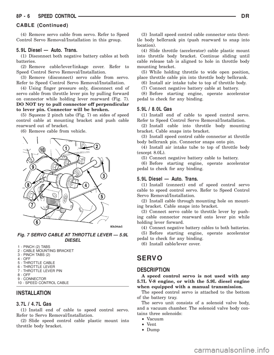
(4) Using finger pressure only, disconnect end of
servo cable from throttle lever pin by pulling forward
on connector while holding lever rearward (Fig. 7).
DO NOT try to pull connector off perpendicular
to lever pin. Connector will be broken.
(5) Squeeze 2 pinch tabs (Fig. 7) on sides of speed
control cable at mounting bracket and push cable
rearward out of bracket.
(6) Remove cable from vehicle.
INSTALLATION
3.7L / 4.7L Gas
(1) Install end of cable to speed control servo.
Refer to Servo Removal/Installation.
(2) Slide speed control cable plastic mount into
throttle body bracket.(3) Install speed control cable connector onto throt-
tle body bellcrank pin (push rearward to snap into
location).
(4) Slide throttle (accelerator) cable plastic mount
into throttle body bracket. Continue sliding until
cable release tab is aligned to hole in throttle body
mounting bracket.
(5) While holding throttle to wide open position,
place throttle cable pin into throttle body bellcrank.
(6) Install air intake tube to top of throttle body.
(7) Connect negative battery cable at battery.
(8) Before starting engine, operate accelerator
pedal to check for any binding.
5.9L / 8.0L Gas
(1) Install end of cable to speed control servo.
Refer to Speed Control Servo Removal/Installation.
(2) Install cable into throttle body mounting
bracket. Cable snaps into bracket.
(3) Install speed control cable connector at throttle
body bellcrank pin. Connector snaps onto pin.
(4) Install air intake tube to top of throttle body
(except 8.0L).
(5) Connect negative battery cable to battery.
(6) Before starting engine, operate accelerator
pedal to check for any binding.
5.9L Diesel Ð Auto. Trans.
(1) Install (connect) end of speed control servo
cable to speed control servo. Refer to Speed Control
Servo Removal/Installation.
(2) Install cable through mounting hole on mount-
ing bracket. Cable snaps into bracket.
(3) Connect servo cable to throttle lever by push-
ing cable connector rearward onto lever pin while
holding lever forward.
(4)
Connect negative battery cables to both batteries.
(5) Before starting engine, operate accelerator
pedal to check for any binding.
(6) Install cable/lever cover.
SERVO
DESCRIPTION
A speed control servo is not used with any
5.7L V-8 engine, or with the 5.9L diesel engine
when equipped with a manual transmission.
The speed control servo is attached to the bottom
of the battery tray.
The servo unit consists of a solenoid valve body,
and a vacuum chamber. The solenoid valve body con-
tains three solenoids:
²Vacuum
²Vent
²Dump
Fig. 7 SERVO CABLE AT THROTTLE LEVER Ð 5.9L
DIESEL
1 - PINCH (2) TABS
2 - CABLE MOUNTING BRACKET
3 - PINCH TABS (2)
4 - OFF
5 - THROTTLE CABLE
6 - THROTTLE LEVER
7 - THROTTLE LEVER PIN
8 - OFF
9 - CONNECTOR
10 - SPEED CONTROL CABLE
8P - 6 SPEED CONTROLDR
CABLE (Continued)