2003 DODGE RAM engine
[x] Cancel search: enginePage 2111 of 2895
OPERATION
NOTE: Refer to the Hydraulic Schematics for a visual
aid in determining valve location, operation and design.
CHECK BALLS
CHECK BALL
NUMBERDESCRIPTION
1 Allows either the manual valve to put line pressure on the 1-2 governor plug or the KD Valve to
put WOT line pressure on the 1-2 governor plug.
2 Allows either the manual valve to put line pressure on the 2-3 governor plug or the KD Valve to
put WOT line pressure on the 2-3 governor plug.
3 Allows either the Reverse circuit or the 3rd gear circuit to pressurize the front clutch.
4 Allows either the Manual Low circuit from the Manual Valve or the Reverse from the Manual
Valve circuit to pressurize the rear servo.
5 Directs line pressure to the spring end of the 2-3 shift valve in either Manual Low or Manual
2nd, forcing the downshift to 2nd gear regardless of governor pressure.
6 Provides a by-pass around the front servo orifice so that the servo can release quickly.
7 Provides a by-pass around the rear clutch orifice so that the clutch can release quickly.
8 Directs reverse line pressure through an orifice to the throttle valve eliminating the extra
leakage and insuring that Reverse line pressure pressure will be sufficient.
9 Provides a by-pass around the rear servo orifice so that the servo can release quickly.
10 Allows the lockup clutch to used at WOT in 3rd gear by putting line pressure from the 3-4
Timing Valve on the interlock area of the 2-3 shift valve, thereby preventing a 3rd gear Lock-up
to 2nd gear kickdown.
REGULATOR VALVE
The pressure regulator valve is needed to control
the hydraulic pressure within the system and reduce
the amount of heat produced in the fluid. The pres-
sure regulator valve is located in the valve body near
the manual valve. The pressure regulator valve train
controls the maximum pressure in the lines by
metering the dumping of fluid back into the sump.
Regulated pressure is referred to as ªline pressure.º
The regulator valve (Fig. 271) has a spring on one
end that pushes the valve to the left. This closes a
dump (vent) that is used to lower pressure. The closing
of the dump will cause the oil pressure to increase. Oil
pressure on the opposite end of the valve pushes the
valve to the right, opening the dump and lowering oil
pressure. The result is spring pressure working against
oil pressure to maintain the oil at specific pressures.
With the engine running, fluid flows from the pump to
the pressure regulator valve, manual valve, and the
interconnected circuits. As fluid is sent through pas-
sages to the regulator valve, the pressure pushes the
valve to the right against the large spring. It is also
sent to the reaction areas on the left side of the throttle
pressure plug and the line pressure plug. With the gearselector in the PARK position, fluid recirculates through
the regulator and manual valves back to the sump.
Meanwhile, the torque converter is filled slowly. In
all other gear positions (Fig. 272), fluid flows
between two right side lands to the switch valve and
torque converter. At low pump speeds, the flow is
controlled by the pressure valve groove to reduce
pressure to the torque converter. After the torque
converter and switch valve fill with fluid, the switch
valve becomes the controlling metering device for
torque converter pressure. The regulator valve then
begins to control the line pressure for the other
transmission circuits. The balance of the fluid pres-
sure pushing the valve to the right and the spring
pressure pushing to the left determines the size of
the metering passage at land #2 (land #1 being at
the far right of the valve in the diagram). As fluid
leaks past the land, it moves into a groove connected
to the filter or sump. As the land meters the fluid to
the sump, it causes the pressure to reduce and the
spring decreases the size of the metering passage.
When the size of the metering passage is reduced,
the pressure rises again and the size of the land is
increased again. Pressure is regulated by this con-
stant balance of hydraulic and spring pressure.
21 - 272 AUTOMATIC TRANSMISSION - 46REDR
VALVE BODY (Continued)
Page 2121 of 2895
THROTTLE VALVE
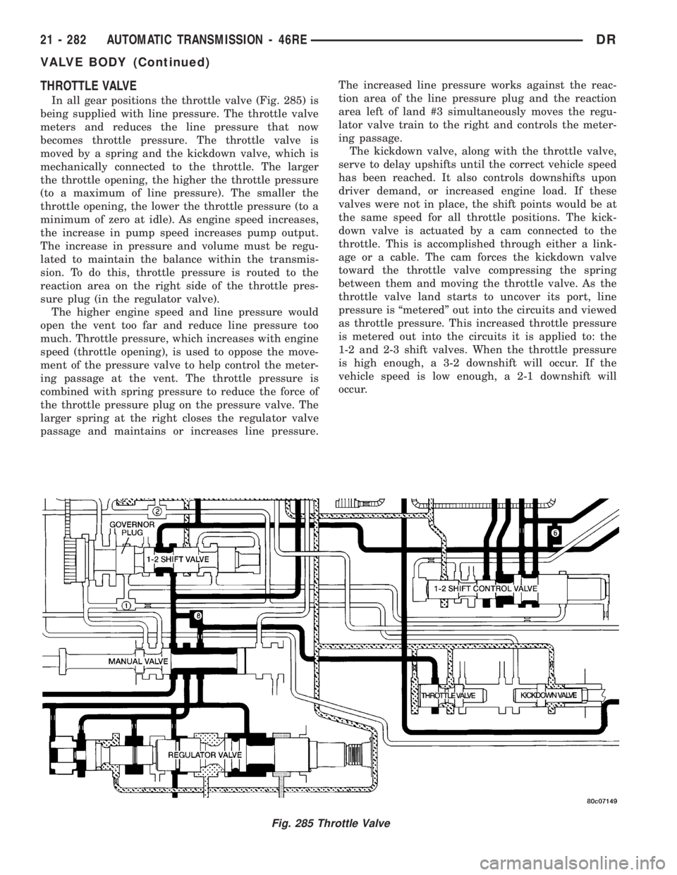
In all gear positions the throttle valve (Fig. 285) is
being supplied with line pressure. The throttle valve
meters and reduces the line pressure that now
becomes throttle pressure. The throttle valve is
moved by a spring and the kickdown valve, which is
mechanically connected to the throttle. The larger
the throttle opening, the higher the throttle pressure
(to a maximum of line pressure). The smaller the
throttle opening, the lower the throttle pressure (to a
minimum of zero at idle). As engine speed increases,
the increase in pump speed increases pump output.
The increase in pressure and volume must be regu-
lated to maintain the balance within the transmis-
sion. To do this, throttle pressure is routed to the
reaction area on the right side of the throttle pres-
sure plug (in the regulator valve).
The higher engine speed and line pressure would
open the vent too far and reduce line pressure too
much. Throttle pressure, which increases with engine
speed (throttle opening), is used to oppose the move-
ment of the pressure valve to help control the meter-
ing passage at the vent. The throttle pressure is
combined with spring pressure to reduce the force of
the throttle pressure plug on the pressure valve. The
larger spring at the right closes the regulator valve
passage and maintains or increases line pressure.The increased line pressure works against the reac-
tion area of the line pressure plug and the reaction
area left of land #3 simultaneously moves the regu-
lator valve train to the right and controls the meter-
ing passage.
The kickdown valve, along with the throttle valve,
serve to delay upshifts until the correct vehicle speed
has been reached. It also controls downshifts upon
driver demand, or increased engine load. If these
valves were not in place, the shift points would be at
the same speed for all throttle positions. The kick-
down valve is actuated by a cam connected to the
throttle. This is accomplished through either a link-
age or a cable. The cam forces the kickdown valve
toward the throttle valve compressing the spring
between them and moving the throttle valve. As the
throttle valve land starts to uncover its port, line
pressure is ªmeteredº out into the circuits and viewed
as throttle pressure. This increased throttle pressure
is metered out into the circuits it is applied to: the
1-2 and 2-3 shift valves. When the throttle pressure
is high enough, a 3-2 downshift will occur. If the
vehicle speed is low enough, a 2-1 downshift will
occur.
Fig. 285 Throttle Valve
21 - 282 AUTOMATIC TRANSMISSION - 46REDR
VALVE BODY (Continued)
Page 2151 of 2895
AUTOMATIC TRANSMISSION -
48RE
DESCRIPTION
The 48RE (Fig. 1) is a four speed fully automatic
transmission with an electronic governor. The 48RE
is equipped with a lock-up clutch in the torque con-
verter. First through third gear ranges are provided
by the clutches, bands, overrunning clutch, and plan-
etary gear sets in the transmission. Fourth gear
range is provided by the overdrive unit that contains
an overdrive clutch, direct clutch, planetary gear set,
and overrunning clutch.
The transmission contains a front, rear, and direct
clutch which function as the input driving compo-
nents. It also contains the kickdown (front) and thelow/reverse (rear) bands which, along with the over-
running clutch and overdrive clutch, serve as the
holding components. The driving and holding compo-
nents combine to select the necessary planetary gear
components, in the front, rear, or overdrive planetary
gear set, transfer the engine power from the input
shaft through to the output shaft.
The valve body is mounted to the lower side of the
transmission and contains the valves to control pres-
sure regulation, fluid flow control, and clutch/band
application. The oil pump is mounted at the front of
the transmission and is driven by the torque con-
verter hub. The pump supplies the oil pressure nec-
essary for clutch/band actuation and transmission
lubrication.
21 - 312 AUTOMATIC TRANSMISSION - 48REDR
Page 2153 of 2895
IDENTIFICATION
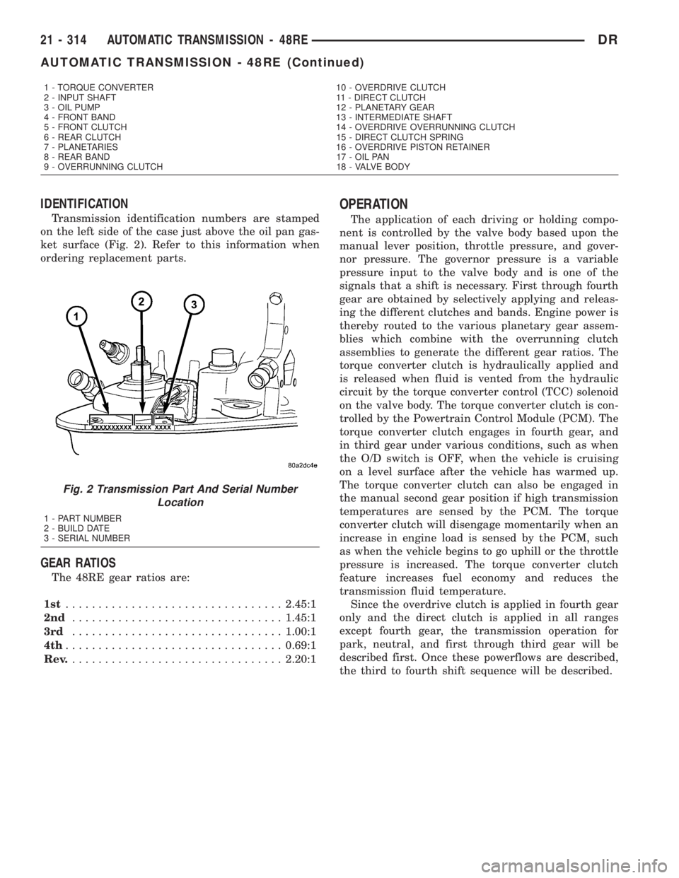
Transmission identification numbers are stamped
on the left side of the case just above the oil pan gas-
ket surface (Fig. 2). Refer to this information when
ordering replacement parts.
GEAR RATIOS
The 48RE gear ratios are:
1st.................................2.45:1
2nd................................1.45:1
3rd................................1.00:1
4th.................................0.69:1
Rev.................................2.20:1
OPERATION
The application of each driving or holding compo-
nent is controlled by the valve body based upon the
manual lever position, throttle pressure, and gover-
nor pressure. The governor pressure is a variable
pressure input to the valve body and is one of the
signals that a shift is necessary. First through fourth
gear are obtained by selectively applying and releas-
ing the different clutches and bands. Engine power is
thereby routed to the various planetary gear assem-
blies which combine with the overrunning clutch
assemblies to generate the different gear ratios. The
torque converter clutch is hydraulically applied and
is released when fluid is vented from the hydraulic
circuit by the torque converter control (TCC) solenoid
on the valve body. The torque converter clutch is con-
trolled by the Powertrain Control Module (PCM). The
torque converter clutch engages in fourth gear, and
in third gear under various conditions, such as when
the O/D switch is OFF, when the vehicle is cruising
on a level surface after the vehicle has warmed up.
The torque converter clutch can also be engaged in
the manual second gear position if high transmission
temperatures are sensed by the PCM. The torque
converter clutch will disengage momentarily when an
increase in engine load is sensed by the PCM, such
as when the vehicle begins to go uphill or the throttle
pressure is increased. The torque converter clutch
feature increases fuel economy and reduces the
transmission fluid temperature.
Since the overdrive clutch is applied in fourth gear
only and the direct clutch is applied in all ranges
except fourth gear, the transmission operation for
park, neutral, and first through third gear will be
described first. Once these powerflows are described,
the third to fourth shift sequence will be described.
1 - TORQUE CONVERTER 10 - OVERDRIVE CLUTCH
2 - INPUT SHAFT 11 - DIRECT CLUTCH
3 - OIL PUMP 12 - PLANETARY GEAR
4 - FRONT BAND 13 - INTERMEDIATE SHAFT
5 - FRONT CLUTCH 14 - OVERDRIVE OVERRUNNING CLUTCH
6 - REAR CLUTCH 15 - DIRECT CLUTCH SPRING
7 - PLANETARIES 16 - OVERDRIVE PISTON RETAINER
8 - REAR BAND 17 - OIL PAN
9 - OVERRUNNING CLUTCH 18 - VALVE BODY
Fig. 2 Transmission Part And Serial Number
Location
1 - PART NUMBER
2 - BUILD DATE
3 - SERIAL NUMBER
21 - 314 AUTOMATIC TRANSMISSION - 48REDR
AUTOMATIC TRANSMISSION - 48RE (Continued)
Page 2154 of 2895
PARK POWERFLOW
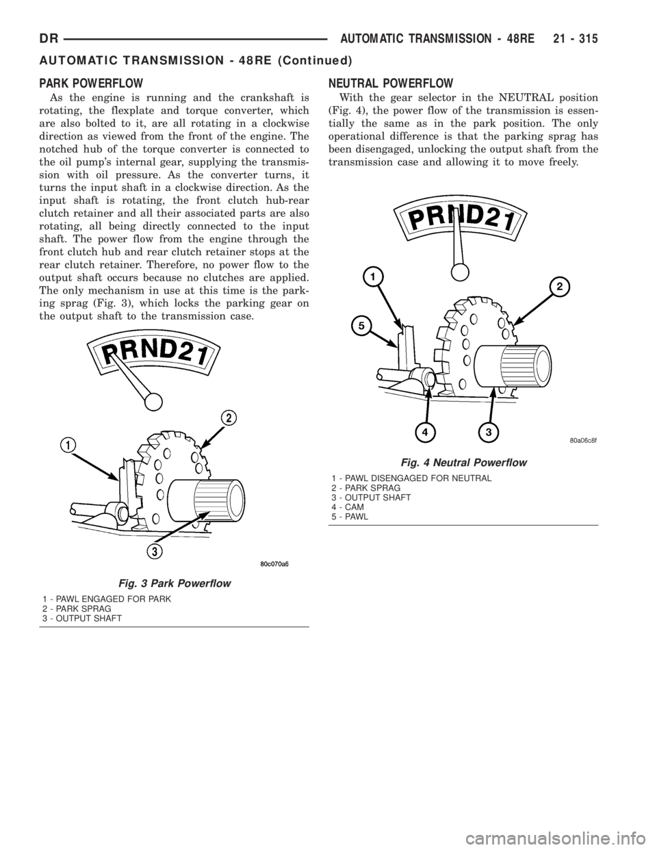
As the engine is running and the crankshaft is
rotating, the flexplate and torque converter, which
are also bolted to it, are all rotating in a clockwise
direction as viewed from the front of the engine. The
notched hub of the torque converter is connected to
the oil pump's internal gear, supplying the transmis-
sion with oil pressure. As the converter turns, it
turns the input shaft in a clockwise direction. As the
input shaft is rotating, the front clutch hub-rear
clutch retainer and all their associated parts are also
rotating, all being directly connected to the input
shaft. The power flow from the engine through the
front clutch hub and rear clutch retainer stops at the
rear clutch retainer. Therefore, no power flow to the
output shaft occurs because no clutches are applied.
The only mechanism in use at this time is the park-
ing sprag (Fig. 3), which locks the parking gear on
the output shaft to the transmission case.
NEUTRAL POWERFLOW
With the gear selector in the NEUTRAL position
(Fig. 4), the power flow of the transmission is essen-
tially the same as in the park position. The only
operational difference is that the parking sprag has
been disengaged, unlocking the output shaft from the
transmission case and allowing it to move freely.
Fig. 3 Park Powerflow
1 - PAWL ENGAGED FOR PARK
2 - PARK SPRAG
3 - OUTPUT SHAFT
Fig. 4 Neutral Powerflow
1 - PAWL DISENGAGED FOR NEUTRAL
2 - PARK SPRAG
3 - OUTPUT SHAFT
4 - CAM
5-PAWL
DRAUTOMATIC TRANSMISSION - 48RE 21 - 315
AUTOMATIC TRANSMISSION - 48RE (Continued)
Page 2155 of 2895
REVERSE POWERFLOW
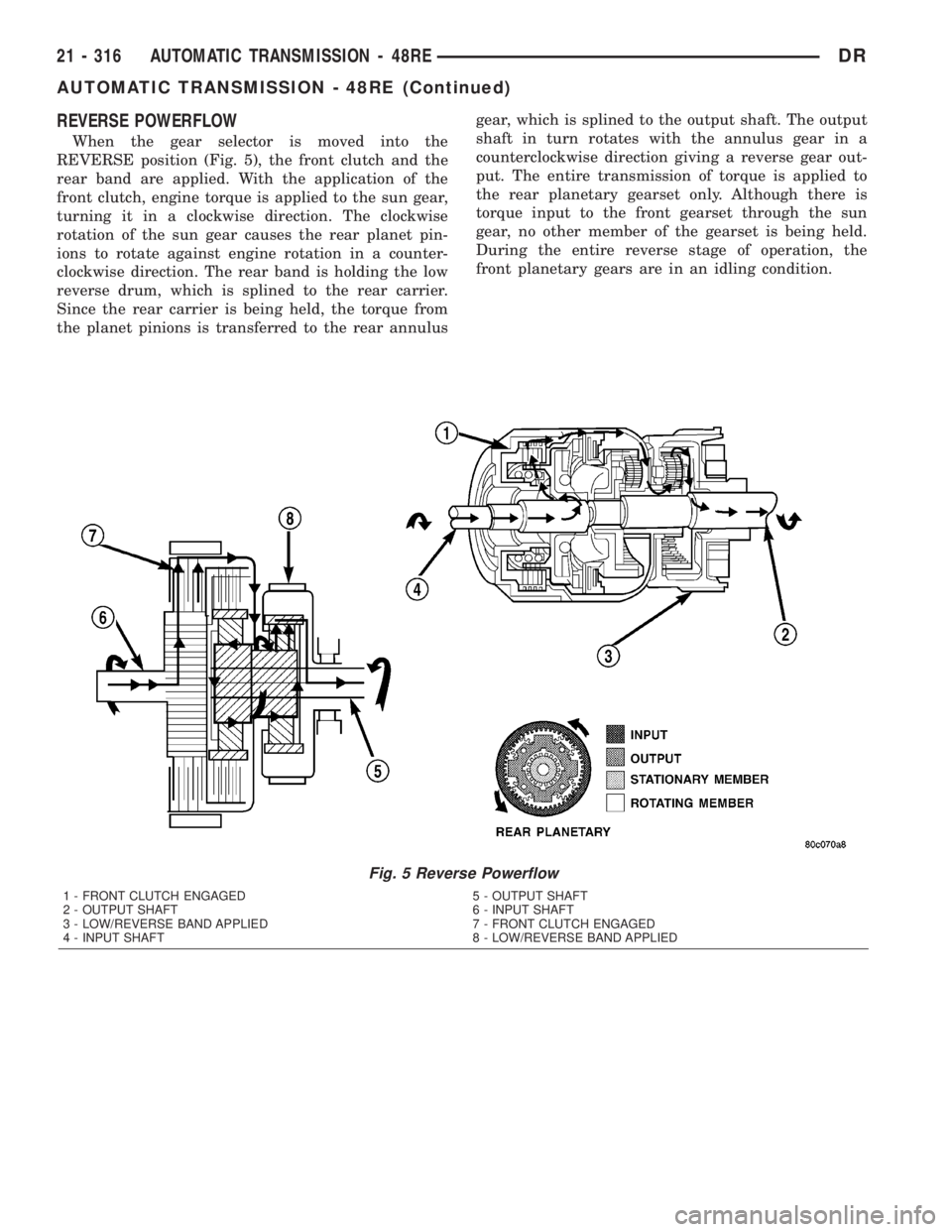
When the gear selector is moved into the
REVERSE position (Fig. 5), the front clutch and the
rear band are applied. With the application of the
front clutch, engine torque is applied to the sun gear,
turning it in a clockwise direction. The clockwise
rotation of the sun gear causes the rear planet pin-
ions to rotate against engine rotation in a counter-
clockwise direction. The rear band is holding the low
reverse drum, which is splined to the rear carrier.
Since the rear carrier is being held, the torque from
the planet pinions is transferred to the rear annulusgear, which is splined to the output shaft. The output
shaft in turn rotates with the annulus gear in a
counterclockwise direction giving a reverse gear out-
put. The entire transmission of torque is applied to
the rear planetary gearset only. Although there is
torque input to the front gearset through the sun
gear, no other member of the gearset is being held.
During the entire reverse stage of operation, the
front planetary gears are in an idling condition.
Fig. 5 Reverse Powerflow
1 - FRONT CLUTCH ENGAGED 5 - OUTPUT SHAFT
2 - OUTPUT SHAFT 6 - INPUT SHAFT
3 - LOW/REVERSE BAND APPLIED 7 - FRONT CLUTCH ENGAGED
4 - INPUT SHAFT 8 - LOW/REVERSE BAND APPLIED
21 - 316 AUTOMATIC TRANSMISSION - 48REDR
AUTOMATIC TRANSMISSION - 48RE (Continued)
Page 2156 of 2895
FIRST GEAR POWERFLOW
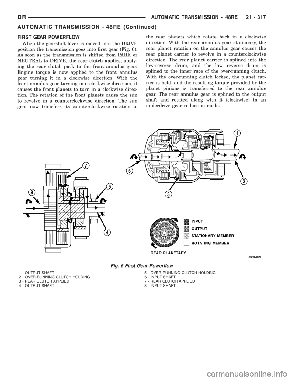
When the gearshift lever is moved into the DRIVE
position the transmission goes into first gear (Fig. 6).
As soon as the transmission is shifted from PARK or
NEUTRAL to DRIVE, the rear clutch applies, apply-
ing the rear clutch pack to the front annulus gear.
Engine torque is now applied to the front annulus
gear turning it in a clockwise direction. With the
front annulus gear turning in a clockwise direction, it
causes the front planets to turn in a clockwise direc-
tion. The rotation of the front planets cause the sun
to revolve in a counterclockwise direction. The sun
gear now transfers its counterclockwise rotation tothe rear planets which rotate back in a clockwise
direction. With the rear annulus gear stationary, the
rear planet rotation on the annulus gear causes the
rear planet carrier to revolve in a counterclockwise
direction. The rear planet carrier is splined into the
low-reverse drum, and the low reverse drum is
splined to the inner race of the over-running clutch.
With the over-running clutch locked, the planet car-
rier is held, and the resulting torque provided by the
planet pinions is transferred to the rear annulus
gear. The rear annulus gear is splined to the output
shaft and rotated along with it (clockwise) in an
underdrive gear reduction mode.
Fig. 6 First Gear Powerflow
1 - OUTPUT SHAFT 5 - OVER-RUNNING CLUTCH HOLDING
2 - OVER-RUNNING CLUTCH HOLDING 6 - INPUT SHAFT
3 - REAR CLUTCH APPLIED 7 - REAR CLUTCH APPLIED
4 - OUTPUT SHAFT 8 - INPUT SHAFT
DRAUTOMATIC TRANSMISSION - 48RE 21 - 317
AUTOMATIC TRANSMISSION - 48RE (Continued)
Page 2157 of 2895
SECOND GEAR POWERFLOW
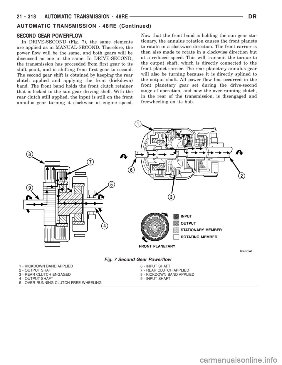
In DRIVE-SECOND (Fig. 7), the same elements
are applied as in MANUAL-SECOND. Therefore, the
power flow will be the same, and both gears will be
discussed as one in the same. In DRIVE-SECOND,
the transmission has proceeded from first gear to its
shift point, and is shifting from first gear to second.
The second gear shift is obtained by keeping the rear
clutch applied and applying the front (kickdown)
band. The front band holds the front clutch retainer
that is locked to the sun gear driving shell. With the
rear clutch still applied, the input is still on the front
annulus gear turning it clockwise at engine speed.Now that the front band is holding the sun gear sta-
tionary, the annulus rotation causes the front planets
to rotate in a clockwise direction. The front carrier is
then also made to rotate in a clockwise direction but
at a reduced speed. This will transmit the torque to
the output shaft, which is directly connected to the
front planet carrier. The rear planetary annulus gear
will also be turning because it is directly splined to
the output shaft. All power flow has occurred in the
front planetary gear set during the drive-second
stage of operation, and now the over-running clutch,
in the rear of the transmission, is disengaged and
freewheeling on its hub.
Fig. 7 Second Gear Powerflow
1 - KICKDOWN BAND APPLIED 6 - INPUT SHAFT
2 - OUTPUT SHAFT 7 - REAR CLUTCH APPLIED
3 - REAR CLUTCH ENGAGED 8 - KICKDOWN BAND APPLIED
4 - OUTPUT SHAFT 9 - INPUT SHAFT
5 - OVER-RUNNING CLUTCH FREE-WHEELING
21 - 318 AUTOMATIC TRANSMISSION - 48REDR
AUTOMATIC TRANSMISSION - 48RE (Continued)