2003 DODGE RAM engine
[x] Cancel search: enginePage 1995 of 2895
STANDARD PROCEDURE - ALUMINUM
THREAD REPAIR
Damaged or worn threads in the aluminum trans-
mission case and valve body can be repaired by the
use of Heli-CoilsŸ, or equivalent. This repair con-
sists of drilling out the worn-out damaged threads.
Then tap the hole with a special Heli-CoilŸ tap, or
equivalent, and installing a Heli-CoilŸ insert, or
equivalent, into the hole. This brings the hole back to
its original thread size.
Heli-CoilŸ, or equivalent, tools and inserts are
readily available from most automotive parts suppli-
ers.
REMOVAL
NOTE: The overdrive unit can be removed and ser-
viced separately. It is not necessary to remove the
entire transmission assembly to perform overdrive
unit repairs.
(1) Disconnect battery negative cable.
(2) Raise vehicle.
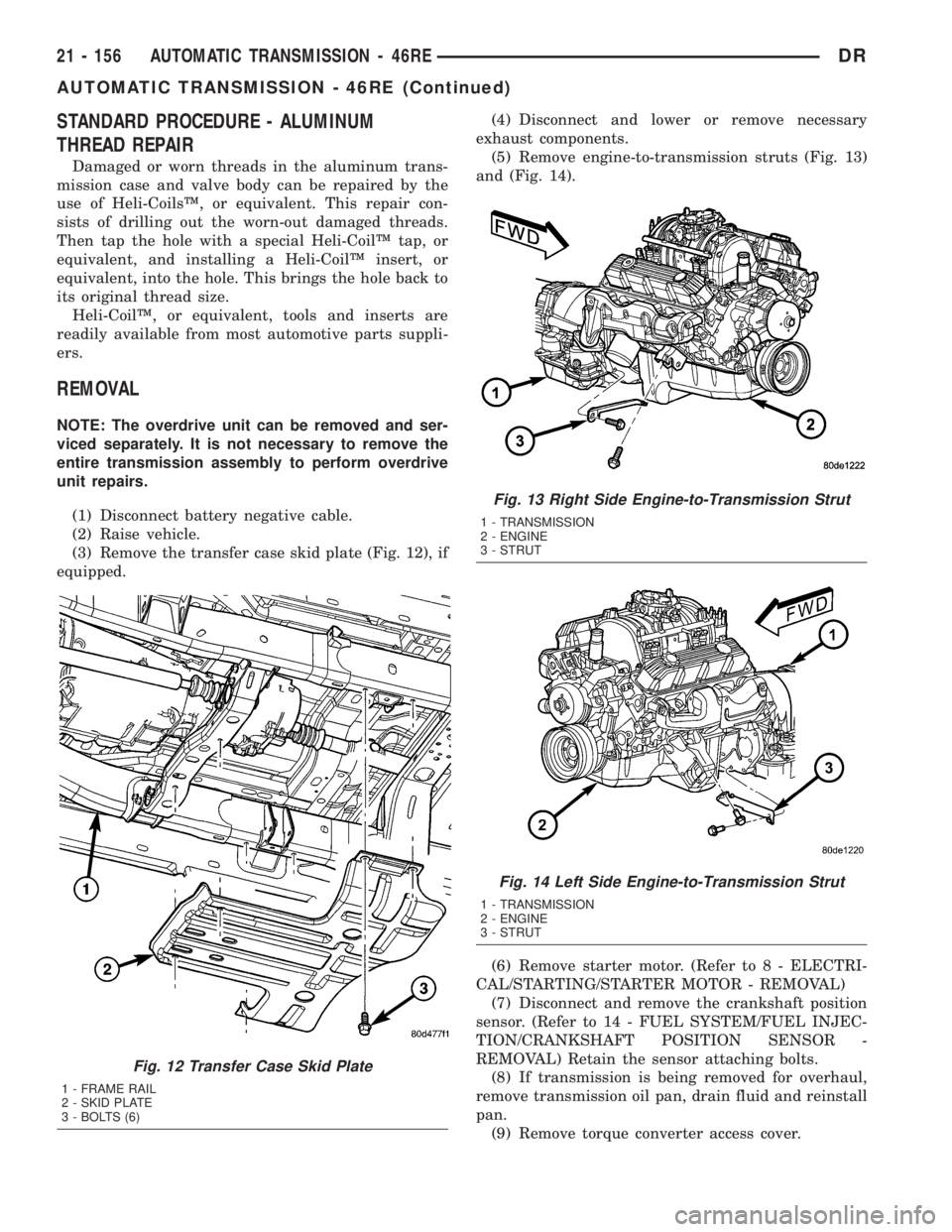
(3) Remove the transfer case skid plate (Fig. 12), if
equipped.(4) Disconnect and lower or remove necessary
exhaust components.
(5) Remove engine-to-transmission struts (Fig. 13)
and (Fig. 14).
(6) Remove starter motor. (Refer to 8 - ELECTRI-
CAL/STARTING/STARTER MOTOR - REMOVAL)
(7) Disconnect and remove the crankshaft position
sensor. (Refer to 14 - FUEL SYSTEM/FUEL INJEC-
TION/CRANKSHAFT POSITION SENSOR -
REMOVAL) Retain the sensor attaching bolts.
(8) If transmission is being removed for overhaul,
remove transmission oil pan, drain fluid and reinstall
pan.
(9) Remove torque converter access cover.
Fig. 12 Transfer Case Skid Plate
1 - FRAME RAIL
2 - SKID PLATE
3 - BOLTS (6)
Fig. 13 Right Side Engine-to-Transmission Strut
1 - TRANSMISSION
2 - ENGINE
3 - STRUT
Fig. 14 Left Side Engine-to-Transmission Strut
1 - TRANSMISSION
2 - ENGINE
3 - STRUT
21 - 156 AUTOMATIC TRANSMISSION - 46REDR
AUTOMATIC TRANSMISSION - 46RE (Continued)
Page 1996 of 2895
(10) Rotate crankshaft in clockwise direction until
converter bolts are accessible. Then remove bolts one
at a time. Rotate crankshaft with socket wrench on
dampener bolt.
(11) Mark propeller shaft and axle yokes for
assembly alignment. Then disconnect and remove
propeller shaft. On4x4models, remove both propel-
ler shafts. (Refer to 3 - DIFFERENTIAL & DRIV-
ELINE/PROPELLER SHAFT/PROPELLER SHAFT -
REMOVAL)
(12) Disconnect wires from the transmission range
sensor and transmission solenoid connector.
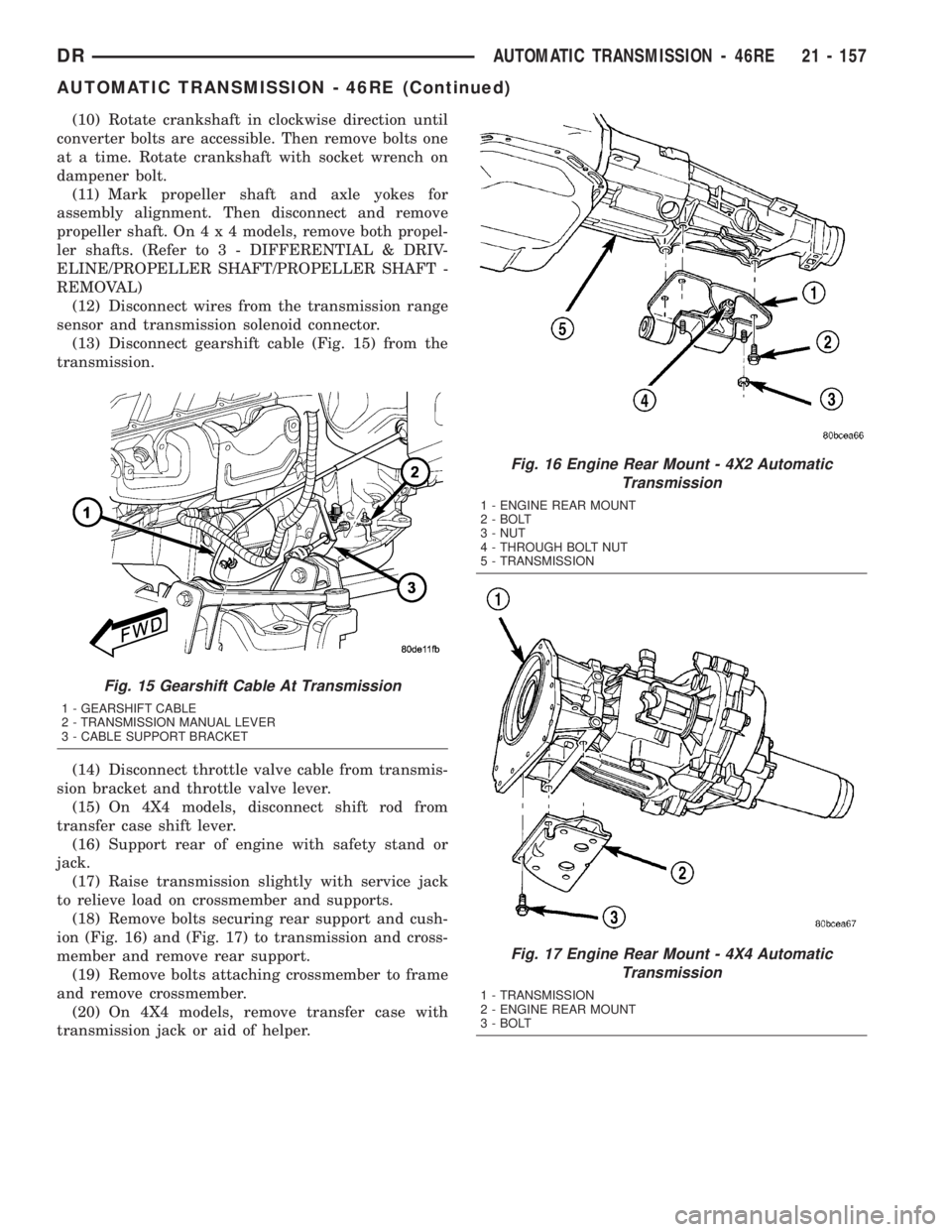
(13) Disconnect gearshift cable (Fig. 15) from the
transmission.
(14) Disconnect throttle valve cable from transmis-
sion bracket and throttle valve lever.
(15) On 4X4 models, disconnect shift rod from
transfer case shift lever.
(16) Support rear of engine with safety stand or
jack.
(17) Raise transmission slightly with service jack
to relieve load on crossmember and supports.
(18) Remove bolts securing rear support and cush-
ion (Fig. 16) and (Fig. 17) to transmission and cross-
member and remove rear support.
(19) Remove bolts attaching crossmember to frame
and remove crossmember.
(20) On 4X4 models, remove transfer case with
transmission jack or aid of helper.
Fig. 15 Gearshift Cable At Transmission
1 - GEARSHIFT CABLE
2 - TRANSMISSION MANUAL LEVER
3 - CABLE SUPPORT BRACKET
Fig. 16 Engine Rear Mount - 4X2 Automatic
Transmission
1 - ENGINE REAR MOUNT
2 - BOLT
3 - NUT
4 - THROUGH BOLT NUT
5 - TRANSMISSION
Fig. 17 Engine Rear Mount - 4X4 Automatic
Transmission
1 - TRANSMISSION
2 - ENGINE REAR MOUNT
3 - BOLT
DRAUTOMATIC TRANSMISSION - 46RE 21 - 157
AUTOMATIC TRANSMISSION - 46RE (Continued)
Page 1997 of 2895
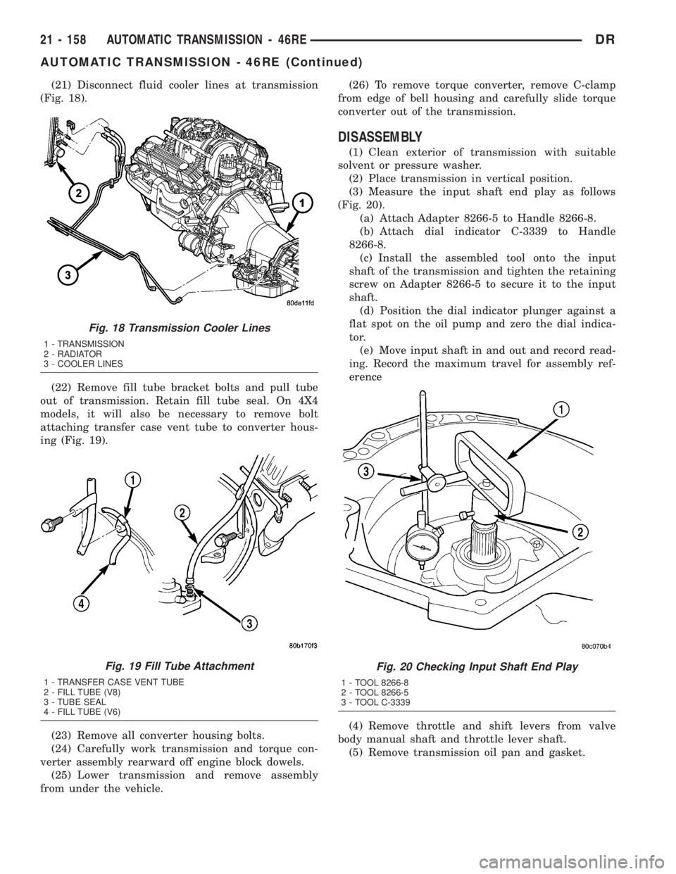
(21) Disconnect fluid cooler lines at transmission
(Fig. 18).
(22) Remove fill tube bracket bolts and pull tube
out of transmission. Retain fill tube seal. On 4X4
models, it will also be necessary to remove bolt
attaching transfer case vent tube to converter hous-
ing (Fig. 19).
(23) Remove all converter housing bolts.
(24) Carefully work transmission and torque con-
verter assembly rearward off engine block dowels.
(25) Lower transmission and remove assembly
from under the vehicle.(26) To remove torque converter, remove C-clamp
from edge of bell housing and carefully slide torque
converter out of the transmission.
DISASSEMBLY
(1) Clean exterior of transmission with suitable
solvent or pressure washer.
(2) Place transmission in vertical position.
(3) Measure the input shaft end play as follows
(Fig. 20).
(a) Attach Adapter 8266-5 to Handle 8266-8.
(b) Attach dial indicator C-3339 to Handle
8266-8.
(c) Install the assembled tool onto the input
shaft of the transmission and tighten the retaining
screw on Adapter 8266-5 to secure it to the input
shaft.
(d) Position the dial indicator plunger against a
flat spot on the oil pump and zero the dial indica-
tor.
(e) Move input shaft in and out and record read-
ing. Record the maximum travel for assembly ref-
erence
(4) Remove throttle and shift levers from valve
body manual shaft and throttle lever shaft.
(5) Remove transmission oil pan and gasket.
Fig. 18 Transmission Cooler Lines
1 - TRANSMISSION
2 - RADIATOR
3 - COOLER LINES
Fig. 19 Fill Tube Attachment
1 - TRANSFER CASE VENT TUBE
2 - FILL TUBE (V8)
3 - TUBE SEAL
4 - FILL TUBE (V6)
Fig. 20 Checking Input Shaft End Play
1 - TOOL 8266-8
2 - TOOL 8266-5
3 - TOOL C-3339
21 - 158 AUTOMATIC TRANSMISSION - 46REDR
AUTOMATIC TRANSMISSION - 46RE (Continued)
Page 2012 of 2895
CAUTION: If the condition of the transmission
before the overhaul procedure caused excessive
metallic or fiber contamination in the fluid, replace
the torque converter. Fluid contamination and trans-
mission failure can result if not done.
(6) Install torque converter. Use C-clamp or metal
strap to hold converter in place for installation.
BAND ADJUSTMENT AND FINAL
(1) Adjust front and rear bands as follows:
(a) Loosen locknut on each band adjusting screw
4-5 turns.
(b) Tighten both adjusting screws to 8 N´m (72
in. lbs.).
(c) Back off front band adjusting screw 2-7/8
turns.
(d) Back off rear band adjusting screw 2 turns.
(e) Hold each adjusting screw in position and
tighten locknut to 34 N´m (25 ft. lbs.) torque.
(2) Install magnet in oil pan. Magnet seats on
small protrusion at corner of pan.
(3) Position new oil pan gasket on case and install
oil pan. Tighten pan bolts to 17 N´m (13 ft. lbs.).
(4) Install throttle valve and shift selector levers
on valve body manual lever shaft.
(5) Apply small quantity of dielectric grease to ter-
minal pins of solenoid case connector and transmis-
sion range sensor.
(6) Fill transmission with recommended fluid.
Refer to Service Procedures section of this group.
INSTALLATION
(1) Check torque converter hub and hub drive
notches for sharp edges burrs, scratches, or nicks.
Polish the hub and notches with 320/400 grit paper
and crocus cloth if necessary. The hub must be
smooth to avoid damaging pump seal at installation.
(2) Lubricate pocket in the rear oil pump seal lip
with transmission fluid.
(3) Lubricate converter pilot hub of the crankshaft
with a light coating of MopartHigh Temp Grease.
(4) Align and install converter in oil pump.
(5) Carefully insert converter in oil pump. Then
rotate converter back and forth until fully seated in
pump gears.
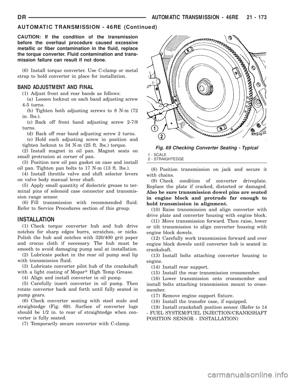
(6) Check converter seating with steel scale and
straightedge (Fig. 69). Surface of converter lugs
should be 1/2 in. to rear of straightedge when con-
verter is fully seated.
(7) Temporarily secure converter with C-clamp.(8) Position transmission on jack and secure it
with chains.
(9) Check condition of converter driveplate.
Replace the plate if cracked, distorted or damaged.
Also be sure transmission dowel pins are seated
in engine block and protrude far enough to
hold transmission in alignment.
(10) Raise transmission and align converter with
drive plate and converter housing with engine block.
(11) Move transmission forward. Then raise, lower
or tilt transmission to align converter housing with
engine block dowels.
(12) Carefully work transmission forward and over
engine block dowels until converter hub is seated in
crankshaft.
(13) Install bolts attaching converter housing to
engine.
(14) Install rear support.
(15) Install the rear transmission crossmember.
(16) Lower transmission onto crossmember and
install bolts attaching transmission mount to cross-
member.
(17) Remove engine support fixture.
(18) Install the transfer case, if equipped.
(19) Install crankshaft position sensor. (Refer to 14
- FUEL SYSTEM/FUEL INJECTION/CRANKSHAFT
POSITION SENSOR - INSTALLATION)
Fig. 69 Checking Converter Seating - Typical
1 - SCALE
2 - STRAIGHTEDGE
DRAUTOMATIC TRANSMISSION - 46RE 21 - 173
AUTOMATIC TRANSMISSION - 46RE (Continued)
Page 2034 of 2895
DIAGNOSIS AND TESTING - BRAKE
TRANSMISSION SHIFT INTERLOCK
(1) Verify that the key can only be removed in the
PARK position
(2) When the shift lever is in PARK And the shift
handle pushbutton is in the ªOUTº position, the igni-
tion key cylinder should rotate freely from OFF to
LOCK. When the shifter is in any other gear or neu-
tral position, the ignition key cylinder should not
rotate to the LOCK position.
(3) Shifting out of PARK should not be possible
when the ignition key cylinder is in the OFF posi-
tion.
(4) Shifting out of PARK should not be possible
while applying normal pushbutton force and ignition
key cylinder is in the RUN or START positions
unless the foot brake pedal is depressed approxi-
mately 1/2 inch (12mm).
(5) Shifting out of PARK should not be possible
when the ignition key cylinder is in the ACCESSORY
or LOCK positions.
(6) Shifting between any gears, NEUTRAL or into
PARK may be done without depressing foot brake
pedal with ignition switch in RUN or START posi-
tions.
ADJUSTMENTS - BRAKE TRANSMISSION
SHIFT INTERLOCK
Correct cable adjustment is important to proper
interlock operation. The gearshift cable must be cor-
rectly adjusted in order to shift out of PARK.
ADJUSTMENT PROCEDURE
(1) Remove the steering column trim as necessary
for access to the brake transmission shift interlock.
(2) Shift the transmission into the PARK position.
(3) Pull upward on both the BTSI lock tab and the
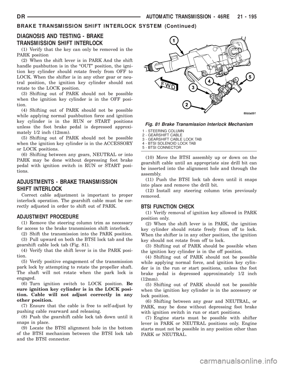
gearshift cable lock tab (Fig. 81).
(4) Verify that the shift lever is in the PARK posi-
tion.
(5) Verify positive engagement of the transmission
park lock by attempting to rotate the propeller shaft.
The shaft will not rotate when the park lock is
engaged.
(6) Turn ignition switch to LOCK position.Be
sure ignition key cylinder is in the LOCK posi-
tion. Cable will not adjust correctly in any
other position.
(7) Ensure that the cable is free to self-adjust by
pushing cable rearward and releasing.
(8) Push the gearshift cable lock tab down until it
snaps in place.
(9) Locate the BTSI alignment hole in the bottom
of the BTSI mechanism between the BTSI lock tab
and the BTSI connector.(10) Move the BTSI assembly up or down on the
gearshift cable until an appropriate size drill bit can
be inserted into the alignment hole and through the
assembly.
(11) Push the BTSI lock tab down until it snaps
into place and remove the drill bit.
(12) Install any steering column trim previously
removed.
BTSI FUNCTION CHECK
(1) Verify removal of ignition key allowed in PARK
position only.
(2) When the shift lever is in PARK, the ignition
key cylinder should rotate freely from off to lock.
When the shifter is in any other position, the ignition
key should not rotate from off to lock.
(3) Shifting out of PARK should be possible when
the ignition key cylinder is in the off position.
(4) Shifting out of PARK should not be possible
while applying normal force, and ignition key cylin-
der is in the run or start positions, unless the foot
brake pedal is depressed approximately 1/2 inch
(12mm).
(5) Shifting out of PARK should not be possible
when the ignition key cylinder is in the accessory or
lock position.
(6) Shifting between any gear and NEUTRAL, or
PARK, may be done without depressing foot brake
with ignition switch in run or start positions.
(7) Engine starts must be possible with shifter
lever in PARK or NEUTRAL positions only. Engine
starts must not be possible in any position other than
PARK or NEUTRAL.
Fig. 81 Brake Transmission Interlock Mechanism
1 - STEERING COLUMN
2 - GEARSHIFT CABLE
3 - GEARSHIFT CABLE LOCK TAB
4 - BTSI SOLENOID LOCK TAB
5 - BTSI CONNECTOR
DRAUTOMATIC TRANSMISSION - 46RE 21 - 195
BRAKE TRANSMISSION SHIFT INTERLOCK SYSTEM (Continued)
Page 2035 of 2895
(8) With shifter lever in the:
²PARK position - Apply upward force on the shift
arm and remove pressure. Engine starts must be
possible.
²PARK position - Apply downward force on the
shift arm and remove pressure. Engine starts must
be possible.
²NEUTRAL position - Normal position. Engine
starts must be possible.
²NEUTRAL position - Engine running and brakes
applied, apply upward force on the shift arm. Trans-
mission shall not be able to shift from neutral to
reverse.
ELECTRONIC GOVERNOR
DESCRIPTION
Governor pressure is controlled electronically. Com-
ponents used for governor pressure control include:
²Governor body
²Valve body transfer plate
²Governor pressure solenoid valve
²Governor pressure sensor
²Fluid temperature thermistor
²Throttle position sensor (TPS)
²Transmission speed sensor
²Powertrain control module (PCM)
GOVERNOR PRESSURE SOLENOID VALVE
The solenoid valve is a duty-cycle solenoid which
regulates the governor pressure needed for upshifts
and downshifts. It is an electro-hydraulic device
located in the governor body on the valve body trans-
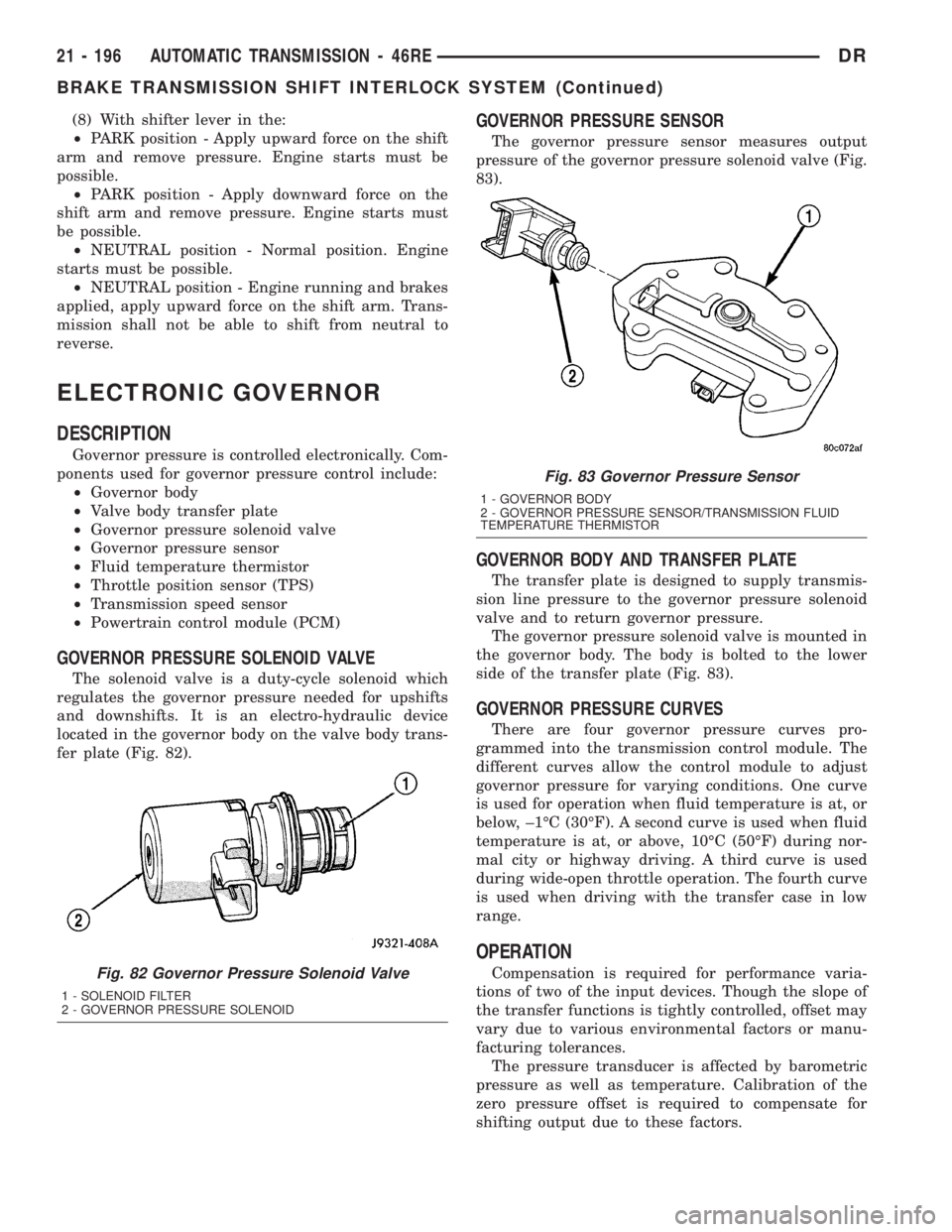
fer plate (Fig. 82).
GOVERNOR PRESSURE SENSOR
The governor pressure sensor measures output
pressure of the governor pressure solenoid valve (Fig.
83).
GOVERNOR BODY AND TRANSFER PLATE
The transfer plate is designed to supply transmis-
sion line pressure to the governor pressure solenoid
valve and to return governor pressure.
The governor pressure solenoid valve is mounted in
the governor body. The body is bolted to the lower
side of the transfer plate (Fig. 83).
GOVERNOR PRESSURE CURVES
There are four governor pressure curves pro-
grammed into the transmission control module. The
different curves allow the control module to adjust
governor pressure for varying conditions. One curve
is used for operation when fluid temperature is at, or
below, ±1ÉC (30ÉF). A second curve is used when fluid
temperature is at, or above, 10ÉC (50ÉF) during nor-
mal city or highway driving. A third curve is used
during wide-open throttle operation. The fourth curve
is used when driving with the transfer case in low
range.
OPERATION
Compensation is required for performance varia-
tions of two of the input devices. Though the slope of
the transfer functions is tightly controlled, offset may
vary due to various environmental factors or manu-
facturing tolerances.
The pressure transducer is affected by barometric
pressure as well as temperature. Calibration of the
zero pressure offset is required to compensate for
shifting output due to these factors.Fig. 82 Governor Pressure Solenoid Valve
1 - SOLENOID FILTER
2 - GOVERNOR PRESSURE SOLENOID
Fig. 83 Governor Pressure Sensor
1 - GOVERNOR BODY
2 - GOVERNOR PRESSURE SENSOR/TRANSMISSION FLUID
TEMPERATURE THERMISTOR
21 - 196 AUTOMATIC TRANSMISSION - 46REDR
BRAKE TRANSMISSION SHIFT INTERLOCK SYSTEM (Continued)
Page 2036 of 2895
Normal calibration will be performed when sump
temperature is above 50 degrees F, or in the absence
of sump temperature data, after the first 10 minutes
of vehicle operation. Calibration of the pressure
transducer offset occurs each time the output shaft
speed falls below 200 RPM. Calibration shall be
repeated each 3 seconds the output shaft speed is
below 200 RPM. A 0.5 second pulse of 95% duty cycle
is applied to the governor pressure solenoid valve
and the transducer output is read during this pulse.
Averaging of the transducer signal is necessary to
reject electrical noise.
Under cold conditions (below 50 degrees F sump),
the governor pressure solenoid valve response may
be too slow to guarantee 0 psi during the 0.5 second
calibration pulse. Calibration pulses are continued
during this period, however the transducer output
valves are discarded. Transducer offset must be read
at key-on, under conditions which promote a stable
reading. This value is retained and becomes the off-
set during the9cold9period of operation.
GOVERNOR PRESSURE SOLENOID VALVE
The inlet side of the solenoid valve is exposed to
normal transmission line pressure. The outlet side of
the valve leads to the valve body governor circuit.
The solenoid valve regulates line pressure to pro-
duce governor pressure. The average current sup-
plied to the solenoid controls governor pressure. One
amp current produces zero kPa/psi governor pres-
sure. Zero amps sets the maximum governor pres-
sure.
The powertrain control module (PCM) turns on the
trans control relay which supplies electrical power to
the solenoid valve. Operating voltage is 12 volts
(DC). The PCM controls the ground side of the sole-
noid using the governor pressure solenoid control cir-
cuit.
GOVERNOR PRESSURE SENSOR
The sensor output signal provides the necessary
feedback to the PCM. This feedback is needed to ade-
quately control governor pressure.
GOVERNOR BODY AND TRANSFER PLATE
The transfer plate channels line pressure to the
solenoid valve through the governor body. It also
channels governor pressure from the solenoid valve
to the governor circuit. It is the solenoid valve that
develops the necessary governor pressure.
GOVERNOR PRESSURE CURVES
LOW TRANSMISSION FLUID TEMPERATURE
When the transmission fluid is cold the conven-
tional governor can delay shifts, resulting in higherthan normal shift speeds and harsh shifts. The elec-
tronically controlled low temperature governor pres-
sure curve is higher than normal to make the
transmission shift at normal speeds and sooner. The
PCM uses a temperature sensor in the transmission
oil sump to determine when low temperature gover-
nor pressure is needed.
NORMAL OPERATION
Normal operation is refined through the increased
computing power of the PCM and through access to
data on engine operating conditions provided by the
PCM that were not available with the previous
stand-alone electronic module. This facilitated the
development of a load adaptive shift strategy - the
ability to alter the shift schedule in response to vehi-
cle load condition. One manifestation of this capabil-
ity is grade9hunting9prevention - the ability of the
transmission logic to delay an upshift on a grade if
the engine does not have sufficient power to main-
tain speed in the higher gear. The 3-2 downshift and
the potential for hunting between gears occurs with a
heavily loaded vehicle or on steep grades. When
hunting occurs, it is very objectionable because shifts
are frequent and accompanied by large changes in
noise and acceleration.
WIDE OPEN THROTTLE OPERATION
In wide-open throttle (WOT) mode, adaptive mem-
ory in the PCM assures that up-shifts occur at the
preprogrammed optimum speed. WOT operation is
determined from the throttle position sensor, which
is also a part of the emission control system. The ini-
tial setting for the WOT upshift is below the opti-
mum engine speed. As WOT shifts are repeated, the
PCM learns the time required to complete the shifts
by comparing the engine speed when the shifts occur
to the optimum speed. After each shift, the PCM
adjusts the shift point until the optimum speed is
reached. The PCM also considers vehicle loading,
grade and engine performance changes due to high
altitude in determining when to make WOT shifts. It
does this by measuring vehicle and engine accelera-
tion and then factoring in the shift time.
TRANSFER CASE LOW RANGE OPERATION
On four-wheel drive vehicles operating in low
range, the engine can accelerate to its peak more
rapidly than in Normal range, resulting in delayed
shifts and undesirable engine9flare.9The low range
governor pressure curve is also higher than normal
to initiate upshifts sooner. The PCM compares elec-
tronic vehicle speed signal used by the speedometer
to the transmission output shaft speed signal to
determine when the transfer case is in low range.
DRAUTOMATIC TRANSMISSION - 46RE 21 - 197
ELECTRONIC GOVERNOR (Continued)
Page 2040 of 2895
FLUID AND FILTER
DIAGNOSIS AND TESTING
DIAGNOSIS AND TESTING - EFFECTS OF
INCORRECT FLUID LEVEL
A low fluid level allows the pump to take in air
along with the fluid. Air in the fluid will cause fluid
pressures to be low and develop slower than normal.
If the transmission is overfilled, the gears churn the
fluid into foam. This aerates the fluid and causing
the same conditions occurring with a low level. In
either case, air bubbles cause fluid overheating, oxi-
dation and varnish buildup which interferes with
valve and clutch operation. Foaming also causes fluid
expansion which can result in fluid overflow from the
transmission vent or fill tube. Fluid overflow can eas-
ily be mistaken for a leak if inspection is not careful.
DIAGNOSIS AND TESTING - CAUSES OF
BURNT FLUID
Burnt, discolored fluid is a result of overheating
which has two primary causes.
(1) A result of restricted fluid flow through the
main and/or auxiliary cooler. This condition is usu-
ally the result of a faulty or improperly installed
drainback valve, a damaged main cooler, or severe
restrictions in the coolers and lines caused by debris
or kinked lines.
(2) Heavy duty operation with a vehicle not prop-
erly equipped for this type of operation. Trailer tow-
ing or similar high load operation will overheat the
transmission fluid if the vehicle is improperly
equipped. Such vehicles should have an auxiliary
transmission fluid cooler, a heavy duty cooling sys-
tem, and the engine/axle ratio combination needed to
handle heavy loads.
DIAGNOSIS AND TESTING - FLUID
CONTAMINATION
Transmission fluid contamination is generally a
result of:
²adding incorrect fluid
²failure to clean dipstick and fill tube when
checking level
²engine coolant entering the fluid
²internal failure that generates debris
²overheat that generates sludge (fluid break-
down)
²failure to replace contaminated converter after
repair
The use of non-recommended fluids can result in
transmission failure. The usual results are erratic
shifts, slippage, abnormal wear and eventual failuredue to fluid breakdown and sludge formation. Avoid
this condition by using recommended fluids only.
The dipstick cap and fill tube should be wiped
clean before checking fluid level. Dirt, grease and
other foreign material on the cap and tube could fall
into the tube if not removed beforehand. Take the
time to wipe the cap and tube clean before withdraw-
ing the dipstick.
Engine coolant in the transmission fluid is gener-
ally caused by a cooler malfunction. The only remedy
is to replace the radiator as the cooler in the radiator
is not a serviceable part. If coolant has circulated
through the transmission, an overhaul is necessary.
The torque converter should be replaced whenever
a failure generates sludge and debris. This is neces-
sary because normal converter flushing procedures
will not remove all contaminants.
STANDARD PROCEDURE
STANDARD PROCEDURE - FLUID LEVEL
CHECK
Low fluid level can cause a variety of conditions
because it allows the pump to take in air along with
the fluid. As in any hydraulic system, air bubbles
make the fluid spongy, therefore, pressures will be
low and build up slowly.
Improper filling can also raise the fluid level too
high. When the transmssion has too much fluid, the
geartrain churns up foam and cause the same condi-
tions which occur with a low fluid level.
In either case, air bubbles can cause overheating
and/or fluid oxidation, and varnishing. This can
interfere with normal valve, clutch, and accumulator
operation. Foaming can also result in fluid escaping
from the transmission vent where it may be mis-
taken for a leak.
After the fluid has been checked, seat the dipstick
fully to seal out water and dirt.
The transmission has a dipstick to check oil level.
It is located on the right side of the engine. Be sure
to wipe all dirt from dipstick handle before removing.
Fluid level is checked with the engine running at
curb idle speed, the transmission in NEUTRAL and
the transmission fluid at normal operating tempera-
ture.The engine should be running at idle
speed for at least one minute, with the vehicle
on level ground.
The transmission fluid level can be checked two
ways.
PROCEDURE ONE
(1) Transmission fluid must be at normal operat-
ing temperature for accurate fluid level check. Drive
DRAUTOMATIC TRANSMISSION - 46RE 21 - 201