2003 DODGE RAM engine
[x] Cancel search: enginePage 1881 of 2895
MANUAL TRANSMISSION - NV4500
TABLE OF CONTENTS
page page
MANUAL TRANSMISSION - NV4500
DESCRIPTION.........................42
OPERATION...........................42
DIAGNOSIS AND TESTING................43
REMOVAL.............................43
DISASSEMBLY.........................44
CLEANING............................60
INSPECTION..........................60
ASSEMBLY............................61
INSTALLATION.........................77
SPECIFICATIONS.......................79
SPECIAL TOOLS.......................79ADAPTER HOUSING SEAL
REMOVAL.............................83
INSTALLATION.........................83
EXTENSION HOUSING SEAL
REMOVAL.............................83
INSTALLATION.........................83
SHIFT MECHANISM
REMOVAL.............................84
INSTALLATION.........................85
SHIFT COVER
REMOVAL.............................86
INSTALLATION.........................86
MANUAL TRANSMISSION -
NV4500
DESCRIPTION
The NV4500 is a five speed constant mesh manual
transmission. All gear ranges including reverse are
synchronized. Fifth gear is an overdrive range. The
transmission has a cast iron gear case and aluminum
shift cover.
Two versions are used, a standard duty for 5.7L
applications and a heavy duty for V10 and Cummins
diesel applications. Main difference is a larger diam-
eter input shaft, for the heavy duty model.
Tapered roller bearings support the drive gear,
mainshaft and countershaft in the gear case. Roller
bearings in the drive gear support the forward end of
the mainshaft. The mainshaft gears are all supported
on caged type roller bearings. Drive gear thrust reac-
tion is controlled by a needle type thrust bearing.
The bearing is located at the forward end of the
mainshaft.
The transmission is a top loader style. The shift
lever is located in a shifter tower which is bolted to
the shift cover and operates the shift forks and rails
directly. The shift forks and rails are all located
within the aluminum cover which is bolted to the top
of the gear case.
IDENTIFICATION
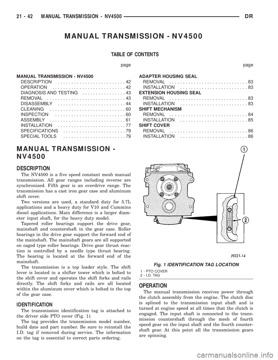
The transmission identification tag is attached to
the driver side PTO cover (Fig. 1).
The tag provides the transmission model number,
build date and part number. Be sure to reinstall the
I.D. tag if removed during service. The information
on the tag is essential to correct parts ordering.
OPERATION
The manual transmission receives power through
the clutch assembly from the engine. The clutch disc
is splined to the transmission input shaft and is
turned at engine speed at all times that the clutch is
engaged. The input shaft is connected to the trans-
mission countershaft through the mesh of fourth
speed gear on the input shaft and the fourth counter-
shaft gear. At this point all the transmission gears
are spinning.
Fig. 1 IDENTIFICATION TAG LOCATION
1 - PTO COVER
2 - I.D. TAG
21 - 42 MANUAL TRANSMISSION - NV4500DR
Page 1883 of 2895
(5) Remove shift tower and isolator plate from
transmission shift cover.
(6) Raise and support vehicle.
(7) Remove skid plate, if equipped.
(8) Mark propeller shaft and axle yokes for instal-
lation reference and remove shaft/shafts.
(9) Remove exhaust system Y-pipe.
(10) Disconnect speed sensor and backup light
switch connectors.
(11) Support engine with safety stand and a wood
block.
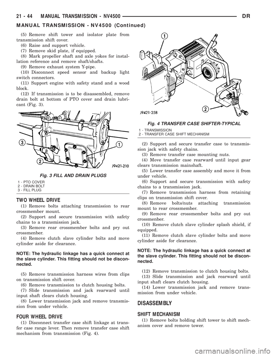
(12) If transmission is to be disassembled, remove
drain bolt at bottom of PTO cover and drain lubri-
cant (Fig. 3).
TWO WHEEL DRIVE
(1) Remove bolts attaching transmission to rear
crossmember mount.
(2) Support and secure transmission with safety
chains to a transmission jack.
(3) Remove rear crossmember bolts and pry out
crossmenber.
(4) Remove clutch slave cylinder bolts and move
cylinder aside for clearance.
NOTE: The hydraulic linkage has a quick connect at
the slave cylinder. This fitting should not be discon-
nected.
(5) Remove transmission harness wires from clips
on transmission shift cover.
(6) Remove transmission to clutch housing bolts.
(7) Slide transmission and jack rearward until
input shaft clears clutch housing.
(8) Lower transmission jack and remove transmis-
sion from under vehicle.
FOUR WHEEL DRIVE
(1) Disconnect transfer case shift linkage at trans-
fer case range lever. Then remove transfer case shift
mechanism from transmission (Fig. 4).(2) Support and secure transfer case to transmis-
sion jack with safety chains.
(3) Remove transfer case mounting nuts.
(4) Move transfer case rearward until input gear
clears transmission mainshaft.
(5) Lower transfer case assembly and move it from
under vehicle.
(6) Support and secure transmission with safety
chains to a transmission jack.
(7) Remove transmission harness from retaining
clips on transmission shift cover.
(8) Remove bolts/nuts attaching transmission
mount to rear crossmember.
(9) Remove rear crossmember bolts and pry out
crossmenber.
(10) Remove clutch slave cylinder splash shield, if
equipped.
(11) Remove clutch slave cylinder bolts and move
cylinder aside for clearance.
NOTE: The hydraulic linkage has a quick connect at
the slave cylinder. This fitting should not be discon-
nected.
(12) Remove transmission to clutch housing bolts.
(13) Slide transmission and jack rearward until
input shaft clears clutch housing.
(14) Lower transmission jack and remove trans-
mission from under vehicle.
DISASSEMBLY
SHIFT MECHANISM
(1) Remove bolts holding shift tower to shift mech-
anism cover and remove tower.
Fig. 3 FILL AND DRAIN PLUGS
1 - PTO COVER
2 - DRAIN BOLT
3 - FILL PLUG
Fig. 4 TRANSFER CASE SHIFTER-TYPICAL
1 - TRANSMISSION
2 - TRANSFER CASE SHIFT MECHANISM
21 - 44 MANUAL TRANSMISSION - NV4500DR
MANUAL TRANSMISSION - NV4500 (Continued)
Page 1917 of 2895
²release fork ball stud.
²propeller shaft slip yoke.
(2) Apply sealer to threads of bottom PTO cover
bolt and install bolt in case.
(3) Mount transmission on jack and position trans-
mission under vehicle.
(4) Raise transmission until input shaft is centered
in release bearing and clutch disc hub.
(5) Move transmission forward and start input
shaft in release bearing, clutch disc and pilot bush-
ing.
(6) Work transmission forward until seated against
clutch housing. Do not allow transmission to remain
unsupported after input shaft has entered clutch
disc.
(7) Install transmission bolts and tighten to 108
N´m (80 ft. lbs.).
(8) Install transmission mount on transmission or
rear crossmember.
(9) Install rear crossmember.
(10) Remove transmission jack and engine support
fixture.
(11) Position transmission harness wires in clips
on shift cover.
(12) Install clutch slave cylinder and install slave
cylinder shield, if equipped.
(13) Connect speed sensor and backup light switch
wires.
TWO WHEEL DRIVE
(1) Fill transmission with recommended lubricant.
Correct fill level is bottom edge of fill plug hole.
(2) Align and install propeller shaft.
(3) Lower vehicle.
(4) Clean the mating surfaces of shift tower, isola-
tor plate and shift cover with suitable wax and
grease remover.
(5) Apply Mopar Gasket Maker or equivalent to
the sealing surface of the shift cover. Do not over
apply sealant.
(6) Install the isolator plate onto the shift cover,
metal side down.
(7) Install the shift tower onto the isolator plate.
No sealant is necessary between the shift tower and
the isolator plate.
(8) Verify that the shift tower, isolator plate and
the shift tower bushings are properly aligned.
(9) Install the bolts to hold the shift tower to the
isolator plate and the shift cover. Tighten the shift
tower bolts to 10.2-11.25 N´m (7.5-8.3 ft. lbs.).
(10) Install the shift lever extension onto the shift
tower and lever assembly.
(11) Install shift boot and bezel.
(12) Connect battery negative cable.
FOUR WHEEL DRIVE
(1) Install transfer case shift mechanism on trans-
mission.
(2) Install transfer case on transmission jack.
Secure transfer case to jack with safety chains.
(3) Raise jack and align transfer case input gear
with transmission mainshaft.
(4) Move transfer case forward and seat it on
adapter.
(5) Install transfer case nuts and tighten to:
²If 3/8 studs 41-47 N´m (30-35 ft. lbs.).
²If 5/16 studs 30-41 N´m (22-30 ft. lbs.).
(6) Install transfer case shift mechanism to side of
transfer case.
(7) Connect transfer case shift lever to range lever
on transfer case.
(8) Align and connect propeller shafts.
(9) Fill transmission with required lubricant.
Check lubricant level in transfer case and add lubri-
cant if necessary.
(10) Install transfer case skid plate, if equipped
and crossmember. Tighten attaching bolts/nuts to 41
N´m (30 ft. lbs.).
(11) Install exhaust system components.
(12) Lower vehicle.
(13) Clean the mating surfaces of shift tower, iso-
lator plate and shift cover with suitable wax and
grease remover.
(14) Apply Mopar Gasket Maker or equivalent to
the sealing surface of the shift cover. Do not over
apply sealant.
(15) Install the isolator plate onto the shift cover,
metal side down.
(16) Install the shift tower onto the isolator plate.
No sealant is necessary between the shift tower and
the isolator plate.
(17) Verify that the shift tower, isolator plate and
the shift tower bushings are properly aligned.
(18) Install the bolts to hold the shift tower to the
isolator plate and the shift cover. Tighten the shift
tower bolts to 10.2-11.25 N´m (7.5-8.3 ft. lbs.).
(19) Install the shift lever extension onto the shift
tower and lever assembly.
(20) Install shift lever boot and bezel.
(21) Connect battery negative cable.
21 - 78 MANUAL TRANSMISSION - NV4500DR
MANUAL TRANSMISSION - NV4500 (Continued)
Page 1922 of 2895
ADAPTER HOUSING SEAL
REMOVAL
(1) Raise and support vehicle.
(2) Mark the propeller shafts and yokes for instal-
lation reference and remove the shafts.
(3) Support transmission with a transmission jack.
(4) Remove engine rear support.
(5) Remove transfer case.
(6) Remove adapter housing seal with a pry tool or
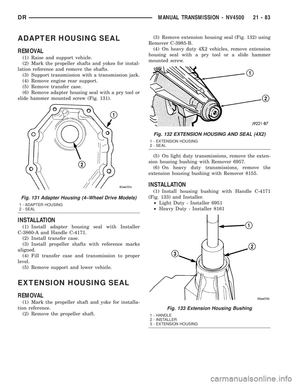
slide hammer mounted screw (Fig. 131).
INSTALLATION
(1) Install adapter housing seal with Installer
C-3860-A and Handle C-4171.
(2) Install transfer case.
(3) Install propeller shafts with reference marks
aligned.
(4) Fill transfer case and transmission to proper
level.
(5) Remove support and lower vehicle.
EXTENSION HOUSING SEAL
REMOVAL
(1) Mark the propeller shaft and yoke for installa-
tion reference.
(2) Remove the propeller shaft.(3) Remove extension housing seal (Fig. 132) using
Remover C-3985-B.
(4) On heavy duty 4X2 vehicles, remove extension
housing seal with a pry tool or a slide hammer
mounted screw.
(5) On light duty transmissions, remove the exten-
sion housing bushing with Remover 6957.
(6) On heavy duty transmissions, remove the
extension housing bushing with Remover 8155.
INSTALLATION
(1) Install housing bushing with Handle C-4171
(Fig. 133) and Installer.
²Light Duty - Installer 6951
²Heavy Duty - Installer 8161
Fig. 131 Adapter Housing (4±Wheel Drive Models)
1 - ADAPTER HOUSING
2 - SEAL
Fig. 132 EXTENSION HOUSING AND SEAL (4X2)
1 - EXTENSION HOUSING
2 - SEAL
Fig. 133 Extension Housing Bushing
1 - HANDLE
2 - INSTALLER
3 - EXTENSION HOUSING
DRMANUAL TRANSMISSION - NV4500 21 - 83
Page 1929 of 2895
(2) Remove screws attaching shift boot to floorpan.
Then slide boot upward on the shift lever.
(3) Remove the bolts holding the shift tower to the
isolator plate and transmission gear case.
(4) Remove the shift tower and isolator plate from
the transmission gear case.
(5) Raise and support vehicle.
(6) Remove skid plate, if equipped.
(7) Mark propeller shaft/shafts and axle yokes for
installation reference.
(8) Remove propeller shaft.
(9) Disconnect and remove exhaust system as nec-
essary.
(10) Disconnect wires at backup light switch.
(11) Support engine with adjustable safety stand
and wood block.
(12) If transmission is to be disassembled for
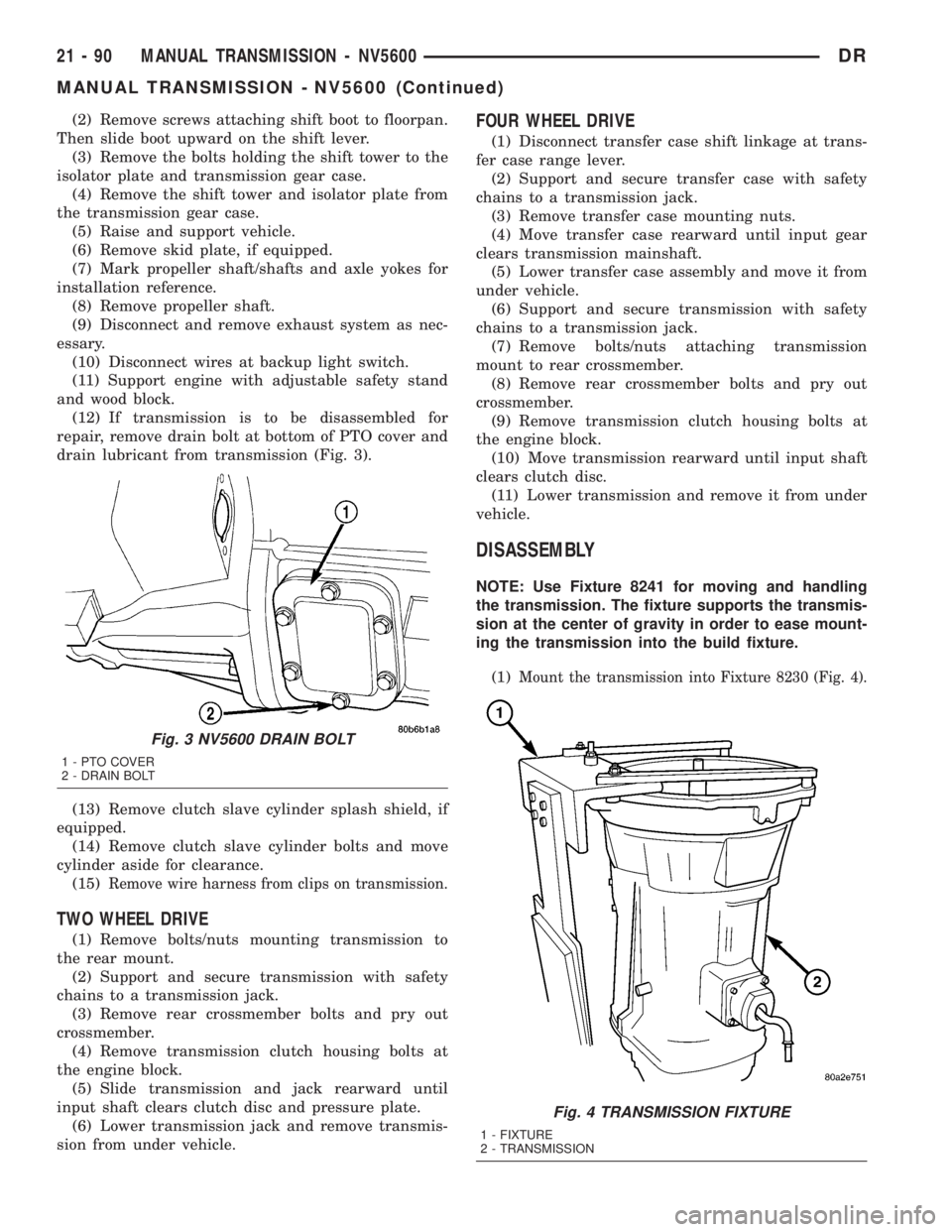
repair, remove drain bolt at bottom of PTO cover and
drain lubricant from transmission (Fig. 3).
(13) Remove clutch slave cylinder splash shield, if
equipped.
(14) Remove clutch slave cylinder bolts and move
cylinder aside for clearance.
(15)
Remove wire harness from clips on transmission.
TWO WHEEL DRIVE
(1) Remove bolts/nuts mounting transmission to
the rear mount.
(2) Support and secure transmission with safety
chains to a transmission jack.
(3) Remove rear crossmember bolts and pry out
crossmember.
(4) Remove transmission clutch housing bolts at
the engine block.
(5) Slide transmission and jack rearward until
input shaft clears clutch disc and pressure plate.
(6) Lower transmission jack and remove transmis-
sion from under vehicle.
FOUR WHEEL DRIVE
(1) Disconnect transfer case shift linkage at trans-
fer case range lever.
(2) Support and secure transfer case with safety
chains to a transmission jack.
(3) Remove transfer case mounting nuts.
(4) Move transfer case rearward until input gear
clears transmission mainshaft.
(5) Lower transfer case assembly and move it from
under vehicle.
(6) Support and secure transmission with safety
chains to a transmission jack.
(7) Remove bolts/nuts attaching transmission
mount to rear crossmember.
(8) Remove rear crossmember bolts and pry out
crossmember.
(9) Remove transmission clutch housing bolts at
the engine block.
(10) Move transmission rearward until input shaft
clears clutch disc.
(11) Lower transmission and remove it from under
vehicle.
DISASSEMBLY
NOTE: Use Fixture 8241 for moving and handling
the transmission. The fixture supports the transmis-
sion at the center of gravity in order to ease mount-
ing the transmission into the build fixture.
(1)
Mount the transmission into Fixture 8230 (Fig. 4).
Fig. 3 NV5600 DRAIN BOLT
1 - PTO COVER
2 - DRAIN BOLT
Fig. 4 TRANSMISSION FIXTURE
1 - FIXTURE
2 - TRANSMISSION
21 - 90 MANUAL TRANSMISSION - NV5600DR
MANUAL TRANSMISSION - NV5600 (Continued)
Page 1935 of 2895
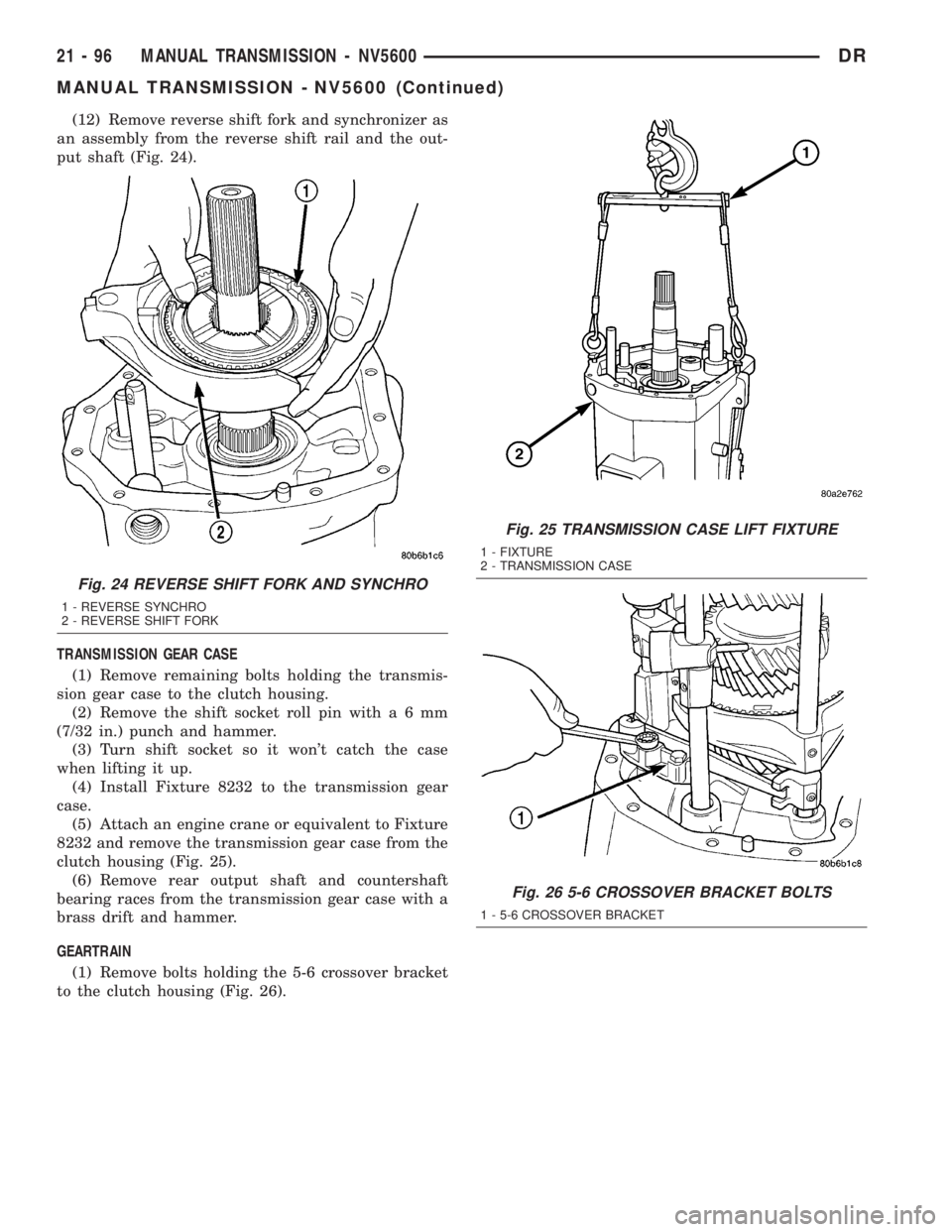
(12) Remove reverse shift fork and synchronizer as
an assembly from the reverse shift rail and the out-
put shaft (Fig. 24).
TRANSMISSION GEAR CASE
(1) Remove remaining bolts holding the transmis-
sion gear case to the clutch housing.
(2) Remove the shift socket roll pin witha6mm
(7/32 in.) punch and hammer.
(3) Turn shift socket so it won't catch the case
when lifting it up.
(4) Install Fixture 8232 to the transmission gear
case.
(5) Attach an engine crane or equivalent to Fixture
8232 and remove the transmission gear case from the
clutch housing (Fig. 25).
(6) Remove rear output shaft and countershaft
bearing races from the transmission gear case with a
brass drift and hammer.
GEARTRAIN
(1) Remove bolts holding the 5-6 crossover bracket
to the clutch housing (Fig. 26).
Fig. 24 REVERSE SHIFT FORK AND SYNCHRO
1 - REVERSE SYNCHRO
2 - REVERSE SHIFT FORK
Fig. 25 TRANSMISSION CASE LIFT FIXTURE
1 - FIXTURE
2 - TRANSMISSION CASE
Fig. 26 5-6 CROSSOVER BRACKET BOLTS
1 - 5-6 CROSSOVER BRACKET
21 - 96 MANUAL TRANSMISSION - NV5600DR
MANUAL TRANSMISSION - NV5600 (Continued)
Page 1936 of 2895
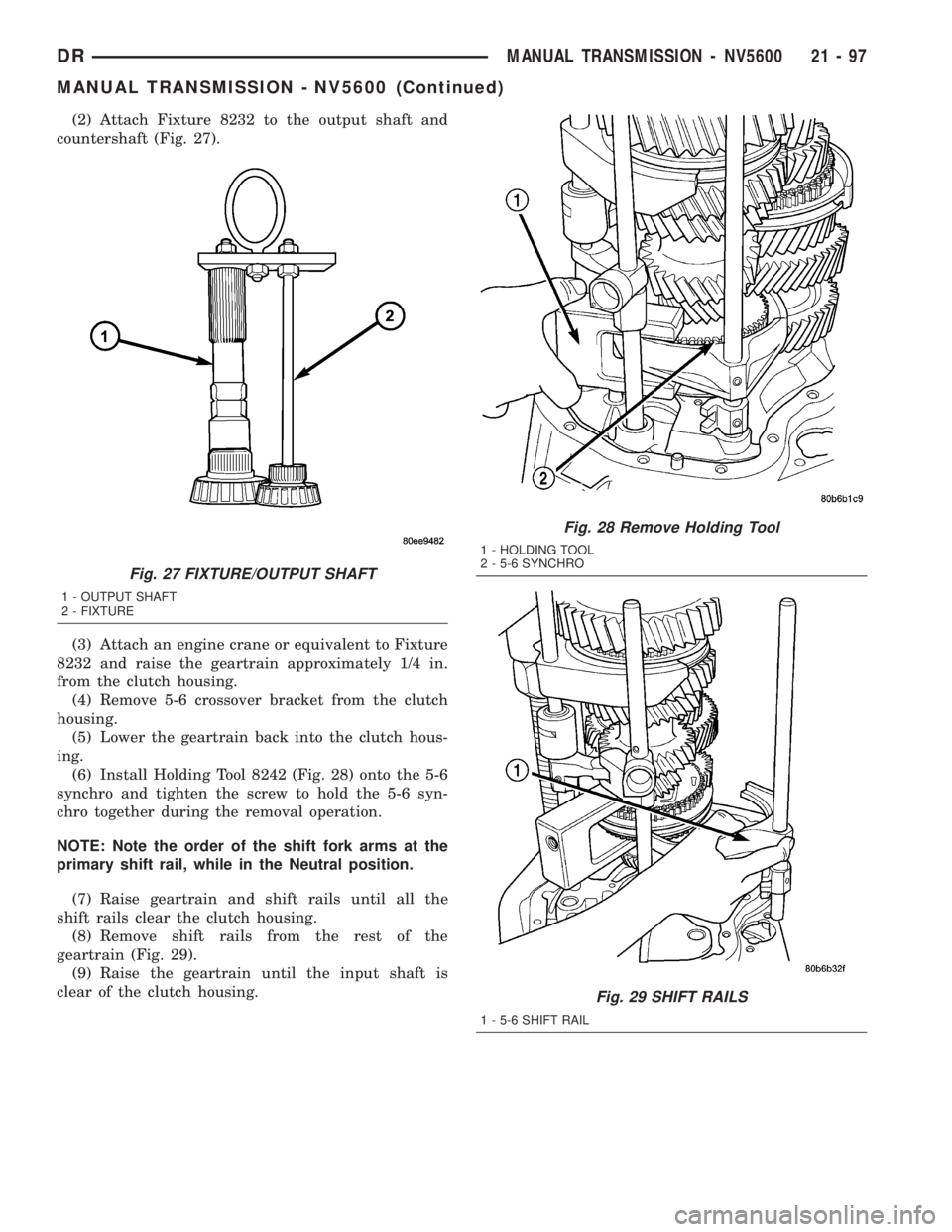
(2) Attach Fixture 8232 to the output shaft and
countershaft (Fig. 27).
(3) Attach an engine crane or equivalent to Fixture
8232 and raise the geartrain approximately 1/4 in.
from the clutch housing.
(4) Remove 5-6 crossover bracket from the clutch
housing.
(5) Lower the geartrain back into the clutch hous-
ing.
(6) Install Holding Tool 8242 (Fig. 28) onto the 5-6
synchro and tighten the screw to hold the 5-6 syn-
chro together during the removal operation.
NOTE: Note the order of the shift fork arms at the
primary shift rail, while in the Neutral position.
(7) Raise geartrain and shift rails until all the
shift rails clear the clutch housing.
(8) Remove shift rails from the rest of the
geartrain (Fig. 29).
(9) Raise the geartrain until the input shaft is
clear of the clutch housing.
Fig. 27 FIXTURE/OUTPUT SHAFT
1 - OUTPUT SHAFT
2 - FIXTURE
Fig. 28 Remove Holding Tool
1 - HOLDING TOOL
2 - 5-6 SYNCHRO
Fig. 29 SHIFT RAILS
1 - 5-6 SHIFT RAIL
DRMANUAL TRANSMISSION - NV5600 21 - 97
MANUAL TRANSMISSION - NV5600 (Continued)
Page 1954 of 2895
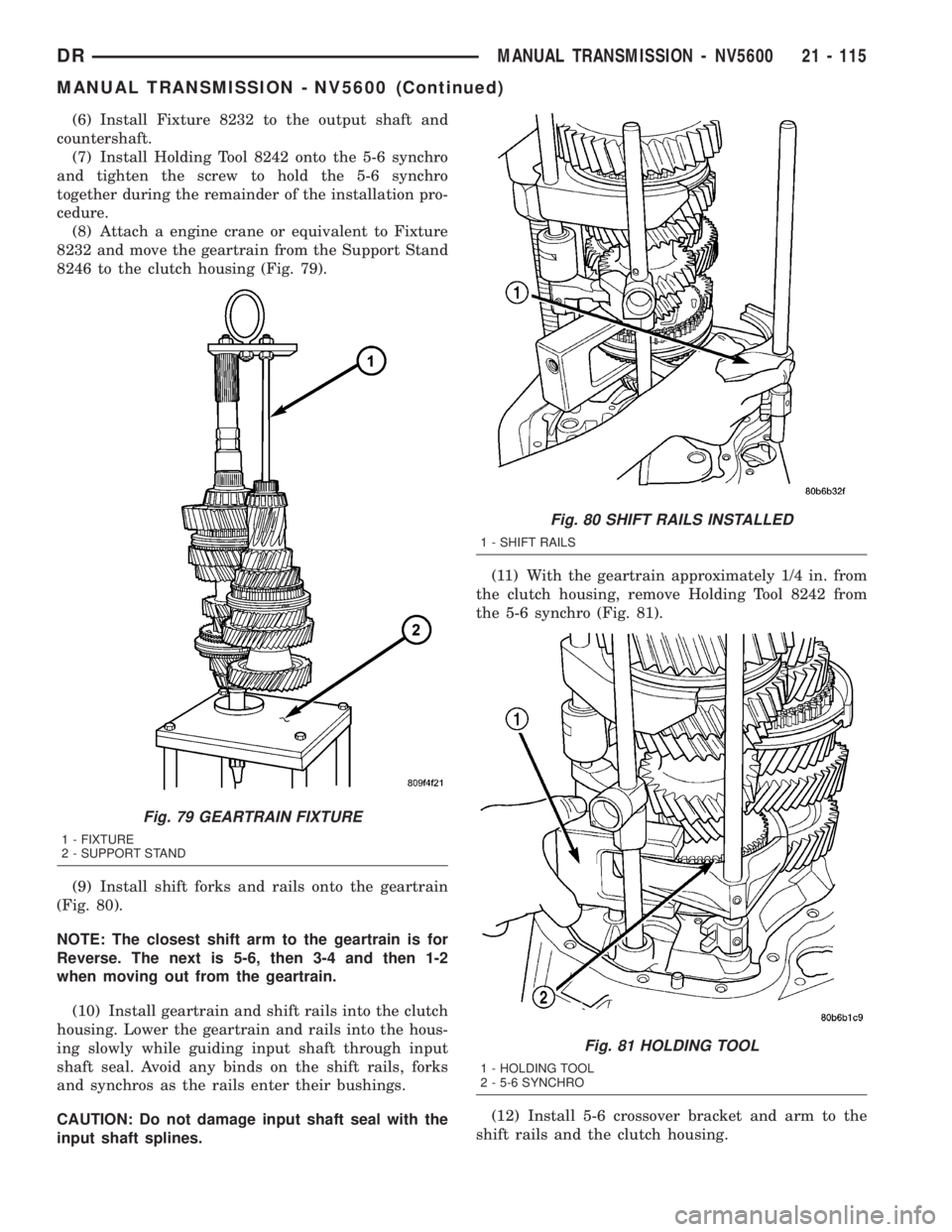
(6) Install Fixture 8232 to the output shaft and
countershaft.
(7) Install Holding Tool 8242 onto the 5-6 synchro
and tighten the screw to hold the 5-6 synchro
together during the remainder of the installation pro-
cedure.
(8) Attach a engine crane or equivalent to Fixture
8232 and move the geartrain from the Support Stand
8246 to the clutch housing (Fig. 79).
(9) Install shift forks and rails onto the geartrain
(Fig. 80).
NOTE: The closest shift arm to the geartrain is for
Reverse. The next is 5-6, then 3-4 and then 1-2
when moving out from the geartrain.
(10) Install geartrain and shift rails into the clutch
housing. Lower the geartrain and rails into the hous-
ing slowly while guiding input shaft through input
shaft seal. Avoid any binds on the shift rails, forks
and synchros as the rails enter their bushings.
CAUTION: Do not damage input shaft seal with the
input shaft splines.(11) With the geartrain approximately 1/4 in. from
the clutch housing, remove Holding Tool 8242 from
the 5-6 synchro (Fig. 81).
(12) Install 5-6 crossover bracket and arm to the
shift rails and the clutch housing.
Fig. 79 GEARTRAIN FIXTURE
1 - FIXTURE
2 - SUPPORT STAND
Fig. 80 SHIFT RAILS INSTALLED
1 - SHIFT RAILS
Fig. 81 HOLDING TOOL
1 - HOLDING TOOL
2 - 5-6 SYNCHRO
DRMANUAL TRANSMISSION - NV5600 21 - 115
MANUAL TRANSMISSION - NV5600 (Continued)