Page 91 of 1690
32092±05
G24249
Oil Hose
Vacuum HoseO±Ring
Vacuum Pump Assy
Vacuum Hose
Check Valve Sub±assy
Vacuum Pump Union Gasket
Straight Pin
Vacuum Pump End Cover Snap Ring
CouplingVaccup Pump Housing
Vacuum pump Blade A
Straight Pin
N�m (kgf�cm, ft�lbf) : Specified torque
� Non±reusable part�
O±Ring �
�
Gasket �
Gasket � �
O±Ring �
Union bolt
7.8 (80, 69 in.�lbf)
7.8 (80, 69 in.�lbf)
7.8 (80, 69 in.�lbf)
14 (140, 10)
21 (214, 15)
21 (214, 15)
Air Cleaner Cap Sub±assy
74 (750, 54)
Connector
Vacuum pump Rotor
32±34
± BRAKEVACUUM PUMP ASSY (1CD±FTV)
AVENSIS REPAIR MANUAL (RM1018E)
COMPONENTS
Page 92 of 1690

32±35
AVENSIS REPAIR MANUAL (RM1018E)
OVERHAUL
1. REMOVE AIR CLEANER CAP SUB±ASSY
2. REMOVE VACUUM PU")
320W2±01
G24251
Vacuum Hose
Oil Hose
F45364
F08966
F08967
± BRAKEVACUUM PUMP ASSY (1CD±FTV)
32±35
AVENSIS REPAIR MANUAL (RM1018E)
OVERHAUL
1. REMOVE AIR CLEANER CAP SUB±ASSY
2. REMOVE VACUUM PUMP ASSY
(a) Disconnect the 2 vacuum hoses and oil hose from the
vacuum pump assy.
(b) Remove the 2 bolts and vacuum pump assy.
(c) Remove the 2 O±rings from the vacuum pump assy.
3. INSPECT VACUUM PUMP ASSY
(a) Turn the coupling counterclockwise direction by hand
when seeing from the coupling direction and check for
any abnormality such as dragging or torque fluctuation.
NOTICE:
Pay coupling attention, because the engine oil remained in
the pump escapes while coupling is turning.
4. REMOVE VACUUM PUMP UNION
(a) Using soft jaws on a vise, hold the vacuum pump assy in
a vise.
NOTICE:
Do not tighten the vise excessively and perform the work
while holding the vacuum pump assy by hand.
(b) Remove the union bolt, vacuum pump union and 2 gas-
kets.
5. REMOVE CHECK VALVE SUB±ASSY
(a) Remove the check valve sub±assy and gasket.
Page 95 of 1690
F08969
F08984
New Gasket
F08985
New Gasket
New Gasket
F45364
32±38
± BRAKEVACUUM PUMP ASSY (1CD±FTV)
AVENSIS REPAIR MANUAL (RM1018E)
(h) Using soft jaws on the vise, hold the vacuum pump in the
vise.
NOTICE:
Do not tighten the vise to tightly.
(i) Tighten the 3 bolts.
Torque: 7.8 N�m (80 kgf�cm, 69 in.�lbf)
14. INSTALL CHECK VALVE SUB±ASSY
(a) Install the check valve sub±assy and a new gasket.
Torque: 74 N�m (750 kgf�cm, 54 ft�lbf)
15. INSTALL VACUUM PUMP UNION
(a) Install the vacuum pump union and 2 new gaskets with
the union bolt.
Torque: 14 N�m (140 kgf�cm, 10 ft�lbf)
HINT:
Align and insert the pin of the union into the matching hole of
the casing.
16. INSPECT VACUUM PUMP ASSY
(a) Turn the gear counterclockwise direction by hand when
seeing from the vacuum pump gear direction and check
for any abnormality such as dragging or torque fluctua-
tion.
Page 96 of 1690

32±39
AVENSIS REPAIR MANUAL (RM1018E)
17. INSTALL VACUUM PUMP ASSY
(a) Coat 2 new O±rings with engine")
G24250
Vacuum HoseNew O±Ring
Oil Hose
F45366
Vacuum Gauge
± BRAKEVACUUM PUMP ASSY (1CD±FTV)
32±39
AVENSIS REPAIR MANUAL (RM1018E)
17. INSTALL VACUUM PUMP ASSY
(a) Coat 2 new O±rings with engine oil, and install them to the
vacuum pump assy.
(b) Install the vacuum pump assy aligning the coupling with
the slit of the camshaft.
(c) Install the 2 bolts.
Torque: 21 N�m (214 kgf�cm, 15 ft�lbf)
(d) Connect 2 vacuum hoses and oil hose.
18. INSPECT CHECK VACUUM PUMP OPERATION
(a) Slide the clip, then disconnect the vacuum hose from vac-
uum pump assy.
(b) Connect the hose of the vacuum gauge to the vacuum
pump assy.
(c) Block off another hose of the vacuum gauge with the hose
clamp No.2.
(d) Start the engine and warm it up for more than 2 minutes.
(e) With the engine idle, check the negative pressure of the
vacuum pump assy.
Standard: More than 650 mmHg (86.7 kPa).
(f) Remove the vacuum gauge from the vacuum pump assy.
(g) Connect the vacuum hose with the clip to the vacuum
pump assy.
19. INSTALL AIR CLEANER CAP SUB±ASSY
Page 97 of 1690

YAWRATE SENSOR
REPLACEMENT
NOTICE:
�Dont use the dropped or damaged yawrate sensor.
�Free from t")
320GM±02
G23169
G23170
G23171
G23170
±
BRAKE YAWRATE SENSOR
32±63
AVENSIS REPAIR MANUAL (RM1018E)
YAWRATE SENSOR
REPLACEMENT
NOTICE:
�Don't use the dropped or damaged yawrate sensor.
�Free from the foreing matters between yawrate sensor braket and body.
�Make sure the sensor direction.
1.REMOVE FRONT SEAT ASSEMBLY LH (See page 72±11 or 72±16)
2. REMOVE YAWRATE SENSOR BRACKET
(a) Remove the bolt and upper part of the yawrate sensorbracket.
3. REMOVE YAWRATE SENSOR
(a) Disconnect the yawrate sensor connector from the yaw- rate sensor.
(b) Remove the 2 bolts and the yawrate sensor with the yaw- rate sensor bracket from the body.
(c) Remove the 2 nuts and yawrate sensor from the yawrate sensor bracket.
4. INSTALL YAWRATE SENSOR
(a) Install the 2 nuts and yawrate sensor to the yawrate sen- sor bracket.
Torque: 6 N �m (61 ft �lbf, 53 in. �lbf)
(b) Install the 2 bolts and the yawrate sensor with the yawrate sensor bracket to the body.
Torque: 21 N �m (214 ft �lbf, 15 ft �lbf)
(c) Connect the yawrate sensor connector to the yawrate sensor.
Page 98 of 1690
G23169
32±64
±
BRAKE YAWRATE SENSOR
AVENSIS REPAIR MANUAL (RM1018E)
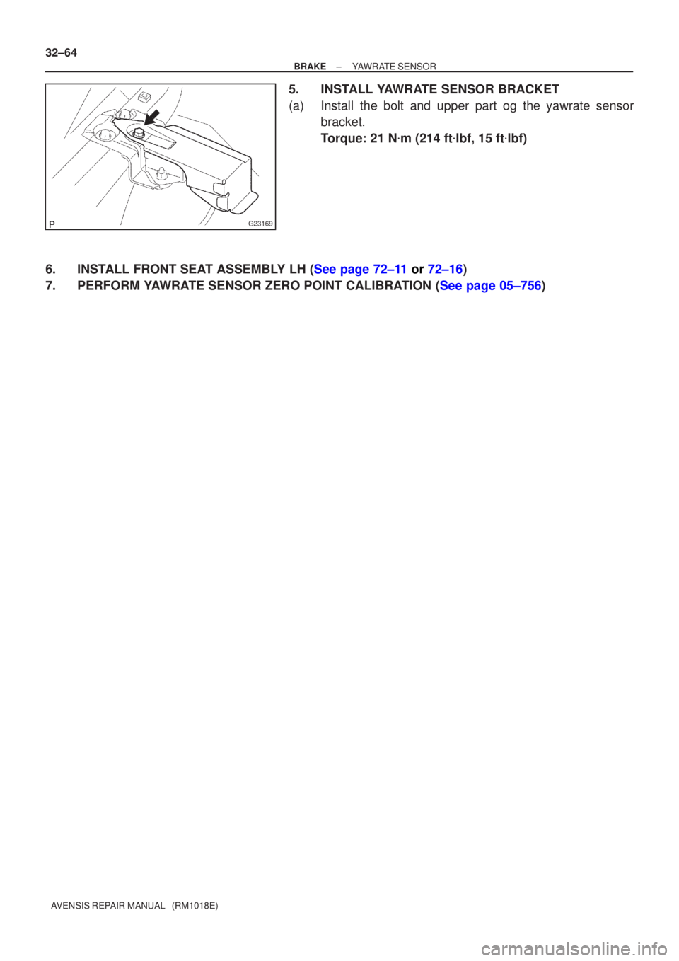
5. INSTALL YAWRATE SENSOR BRACKET
(a) Install the bolt and upper part og the yawrate sensor bracket.
Torque: 21 N �m (214 ft �lbf, 15 ft �lbf)
6.INSTALL FRONT SEAT ASSEMBLY LH (See page 72±11 or 72±16)
7.PERFORM YAWRATE SENSOR ZERO POINT CALIBRATION (See page 05±756)
Page 99 of 1690

YAWRATE SENSOR
REPLACEMENT
NOTICE:
�Dont use the dropped or damaged yawrate sensor.
�Free from t")
320GM±02
G23169
G23170
G23171
G23170
±
BRAKE YAWRATE SENSOR
32±63
AVENSIS REPAIR MANUAL (RM1018E)
YAWRATE SENSOR
REPLACEMENT
NOTICE:
�Don't use the dropped or damaged yawrate sensor.
�Free from the foreing matters between yawrate sensor braket and body.
�Make sure the sensor direction.
1.REMOVE FRONT SEAT ASSEMBLY LH (See page 72±11 or 72±16)
2. REMOVE YAWRATE SENSOR BRACKET
(a) Remove the bolt and upper part of the yawrate sensorbracket.
3. REMOVE YAWRATE SENSOR
(a) Disconnect the yawrate sensor connector from the yaw- rate sensor.
(b) Remove the 2 bolts and the yawrate sensor with the yaw- rate sensor bracket from the body.
(c) Remove the 2 nuts and yawrate sensor from the yawrate sensor bracket.
4. INSTALL YAWRATE SENSOR
(a) Install the 2 nuts and yawrate sensor to the yawrate sen- sor bracket.
Torque: 6 N �m (61 ft �lbf, 53 in. �lbf)
(b) Install the 2 bolts and the yawrate sensor with the yawrate sensor bracket to the body.
Torque: 21 N �m (214 ft �lbf, 15 ft �lbf)
(c) Connect the yawrate sensor connector to the yawrate sensor.
Page 100 of 1690
G23169
32±64
±
BRAKE YAWRATE SENSOR
AVENSIS REPAIR MANUAL (RM1018E)
5. INSTALL YAWRATE SENSOR BRACKET
(a) Install the bolt and upper part og the yawrate sensor bracket.
Torque: 21 N �m (214 ft �lbf, 15 ft �lbf)
6.INSTALL FRONT SEAT ASSEMBLY LH (See page 72±11 or 72±16)
7.PERFORM YAWRATE SENSOR ZERO POINT CALIBRATION (See page 05±756)


AVENSIS REPAIR MANUAL (RM1018E)
(h) Using soft jaws on the vise, hold the vacuum pump in the
v")