Page 75 of 1690

24. INSTALL FRONT DISC BRAKE CYLINDER SLIDE PIN
KIT
(a) Apply")
F45419
Cylinder Slide Pin
Lithium soap base glycol grease
F45421
Union Bolt
±
BRAKE FRONT BRAKE
32±45
AVENSIS REPAIR MANUAL (RM1018E)
24. INSTALL FRONT DISC BRAKE CYLINDER SLIDE PIN
KIT
(a) Apply lithium soap base glycol grease to the a new front
disc brake cylinder slide bush.
(b) Install the front disc brake cylinder slide bush to the bot- tom side of the front disc brake cylinder slide pin (No.2).
(c) Apply lithium soap base glycol grease to the sliding part
and the sealing surface of the 2 cylinder slide pins.
(d) Install the 2 front disc brake cylinder slide pins to the front disc brake cylinder mounting LH.
25. INSTALL FRONT DISC BRAKE PAD KIT
(a) Install the 2 front disc brake pad support plates (No.1) and 2 front disc bra\
ke pad support plates (No.2) to the front disc brake cylinder mounting LH.
(b) Install the disc brake pad kit front to the front disc brake cylinder mo\
unting LH.
NOTICE:
There should be no oil or grease on the friction surfaces of the pads an\
d the disc.
26. INSTALL DISC BRAKE CYLINDER ASSY LH
(a) Install the disc brake cylinder assy LH with the 2 bolts.Torque: 30 N �m (306 kgf �cm, 22 ft �lbf)
(b) Install a new gasket and flexible hose with the union bolt.
Torque: 29 N �m (296 kgf �cm, 21 ft �lbf)
HINT:
Install the flexible hose lock securely in the lock hole in the disc
brake cylinder assy LH.
27.FILL RESERVOIR WITH BRAKE FLUID (See page 32±4)
28.BLEED MASTER CYLINDER (See page 32±4)
(a) w/o VSC: SST 09023±00100
(b) w/ VSC: SST 09023±38400
29.BLEED BRAKE LINE (See page 32±4)
30.CHECK FLUID LEVEL IN RESERVOIR (See page 32±4)
31. CHECK BRAKE FLUID LEAKAGE
32. INSTALL FRONT WHEEL
Torque: 103 N �m (1,050 kgf �cm, 76 ft �lbf)
Page 76 of 1690
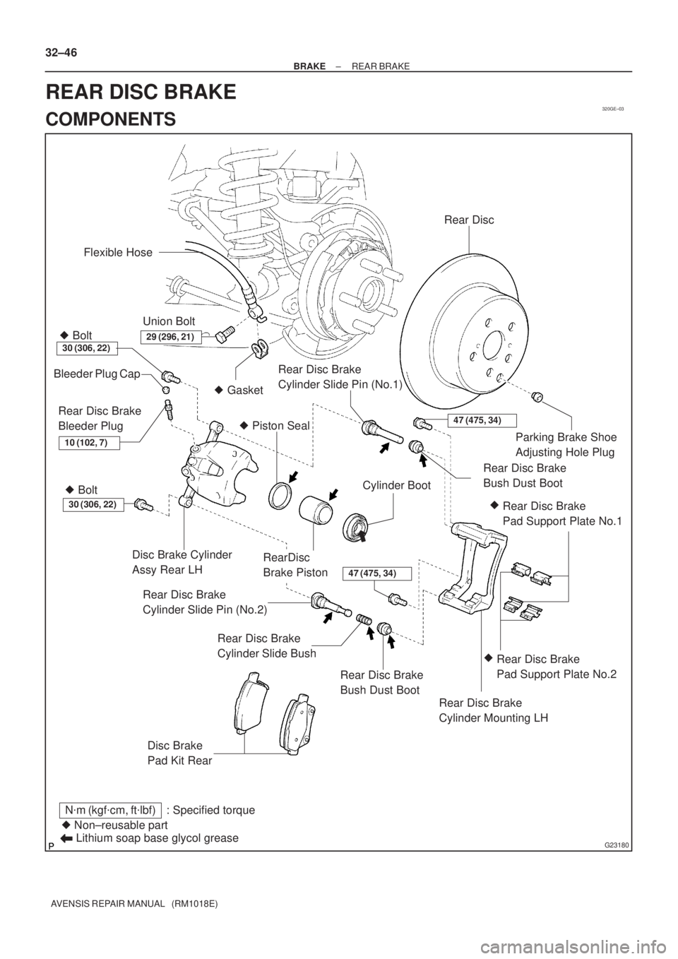
320GE±03
G23180
� Gasket Flexible Hose
30 (306, 22)
Disc Brake Cylinder
Assy Rear LH
Disc Brake
Pad Kit Rear
� Non±reusable part
N�m (kgf�cm, ft�lbf) : Specified torque
Lithium soap base glycol grease
Rear Disc Brake
Bush Dust Boot
Rear Disc Brake
Pad Support Plate No.1
Rear Disc Brake
Cylinder Mounting LH
RearDisc
Brake Piston
Cylinder Boot � Piston Seal
Rear Disc Brake
Cylinder Slide Pin (No.2) Bleeder Plug Cap
Rear Disc Brake
Bleeder Plug
Rear Disc Brake
Cylinder Slide Bush
Rear Disc Brake
Cylinder Slide Pin (No.1)
Rear Disc Brake
Bush Dust Boot Rear Disc
Parking Brake Shoe
Adjusting Hole Plug
47 (475, 34)
30 (306, 22)
47 (475, 34)
29 (296, 21)
10 (102, 7)
Rear Disc Brake
Pad Support Plate No.2
Union Bolt
�� � Bolt � Bolt
32±46
± BRAKEREAR BRAKE
AVENSIS REPAIR MANUAL (RM1018E)
REAR DISC BRAKE
COMPONENTS
Page 80 of 1690

19.INSPECT DISC RUNOUT
(a)Temporarily f")
F45708
F45750Lithium soap base glycol grease
Cylinder Boot
Piston
G23231Cylinder Boot
Piston
F45704
32±50
±
BRAKE REAR BRAKE
AVENSIS REPAIR MANUAL (RM1018E)
19.INSPECT DISC RUNOUT
(a)Temporarily fasten the rear disc with the hub nuts. Torque: 103 N �m (1,050 kgf �cm, 76 ft �lbf)
(b)Using a dial indicator, measure the disc runout 10 mm (0.39 in.) away from the outer edge of the rear disc.
Maximum disc runout: 0.15 mm (0.0059 in.)
(c)If the disc runout is maximum value or greater, check the
bearing play in the axial direction and check for the axle
hub runout (See page 30±2). If the bearing play and axle
hub runout are normal, adjust the disc runout or grind it
on a ºOn±carº brake lathe.
20. TEMPORARILY TIGHTEN REAR DISC BRAKE BLEEDER PLUG
(a) Temporarily install the rear disc brake bleeder plug to the disc brake cy\
linder assy rear LH.
21. INSTALL PISTON SEAL
(a) Apply the lithium soap base glycol grease to a new piston seal.
(b) Install the piston seal to the disc brake cylinder assy rear LH. 22. INSTALL REAR DISC BRAKE PISTON
(a) Apply lithium soap base glycol grease to the rear discbrake piston and a new cylinder boot.
(b) Install the cylinder boot to the rear disc brake piston.
(c) Install the piston to the disc brake cylinder assy LH.
NOTICE:
Do not install the piston forcibly in the disc brake cylinder.
23. INSTALL CYLINDER BOOT
(a) Using SST and a hammer, install the cylinder boot to the disc brake cylinder assy rear LH.
SST 09710±06051
NOTICE:
Do not damage the cylinder boot.
HINT:
Install the boot securely to the disc brake cylinder rear LH.
24. INSTALL REAR DISC BRAKE CYLINDER MOUNTING LH
(a) Install the rear disc brake cylinder mounting LH with the
2 bolts.
Torque: 47 N �m (475 kgf �cm, 34 ft �lbf)
Page 81 of 1690

F45439
Front Disc Brake Cylinder MountingBush Dust Boot
Lithium soap base glycol grease
F45701
Cylinder Slide Pin
Lithium soap base glycol grease
G23181
Union bolt
±
BRAKE REAR BRAKE
32±51
AVENSIS REPAIR MANUAL (RM1018E)
25.INSTALL REAR DISC BRAKE BUSH DUST BOOT
(a)Apply lithium soap base glycol grease to the sealing sur-
face of 2 new bush dust boots.
(b)Install the 2 bush dust boots to the rear disc brake cylinder mounting LH.
26.INSTALL REAR DISC BRAKE CYLINDER SLIDE PIN KIT
(a)Apply lithium soap base glycol grease to sealing surface of a new cylinder slide bush.
(b)Install the rear disc brake cylinder slide bush to the bottom side of the rear disc brake cylinder slide pin (No.2).
(c)Apply lithium soap base glycol grease to the sliding part and the sealing surface of the 2 rear disc brake cylinder
slide pins.
(d)Install the rear disc brake cylinder slide pin (No.1) and rear
disc brake cylinder slide pin (No.2) to the rear disc brake
cylinder mounting LH.
27.INSTALL REAR DISC BRAKE PAD KIT
(a)Install the 2 rear disc brake pad support plates No.1 and 2 rear disc brake pad\
support plate No.2 to the rear disc brake cylinder mounting LH.
(b)Install the disc brake pad kit rear to the disc brake cylinder mounting \
LH.
28.INSTALL DISC BRAKE CYLINDER ASSY REAR LH
(a)Install the disc brake cylinder assy rear LH with the 2 bolts.Torque: 30 N �m (306 kgf �cm, 22 ft �lbf)
(b)Install a new gasket and flexible hose with the union bolt. Torque: 29 N �m (296 kgf �cm, 21 ft �lbf)
HINT:
Install the flexible hose lock securely in to the lock hole in the
disc brake cylinder assy rear LH.
29.FILL RESERVOIR WITH BRAKE FLUID (See page 32±4)
30.BLEED MASTER CYLINDER (See page 32±4)
(a) w/o VSC: SST 09023±00100
(b) w/ VSC: SST 09023±38400
31.BLEED BRAKE LINE (See page 32±4)
32.CHECK FLUID LEVEL IN RESERVOIR (See page 32±4)
Page 82 of 1690
32±52
± BRAKEREAR BRAKE
AVENSIS REPAIR MANUAL (RM1018E)
33. CHECK BRAKE FLUID LEAKAGE
34. INSTALL REAR WHEEL
Torque: 103 N�m (1,050 kgf�cm, 76 ft�lbf)
Page 84 of 1690

7. INSTALL SKID CONTROL SENSOR
(a) Clean the contacting surface of the axle hub and that of a new skid co")
G23168
F08658
SST
G23167
32±62
±
BRAKE SKID CONTROL SENSOR
AVENSIS REPAIR MANUAL (RM1018E)
7. INSTALL SKID CONTROL SENSOR
(a) Clean the contacting surface of the axle hub and that of a new skid control sensor.
NOTICE:
Make sure the sensor rotor is clean.
(b) Place the skid control sensor on the axle hub so that the connector comes into the most downward position under
the on vehicle condition.
(c) Using SST and a press, install the skid control sensor to the axle hub.
NOTICE:
�Do not tap the skid control sensor directly with a ham-
mer.
�Check that there is no foreign matter on the skid con-
trol sensor detection portion.
�Press in the skid control sensor straight and slowly.
SST 09830±36010, 09950±60010 (09951±00650), 09950±70010 (09951±07100)
8.INSTALL REAR AXLE HUB & BEARING ASSY LH (See page 30±31)
9. INSTALL REAR BRAKE DRUM SUB±ASSY
(a) Aligning the matchmarks, install the rear disc.
10. INSTALL REAR DISC BRAKE CALIPER ASSY LH
(a) Install the rear disc brake caliper assy LH with the 2 bolts. Torque: 47 N �m (475 kgf �cm, 34 ft �lbf)
11. CONNECT SKID CONTROL SENSOR WIRE
(a) Connect the connector from the skid control sensor.
12. INSTALL REAR WHEEL Torque: 103 N �m (1,050 kgf �cm, 76 ft �lbf)
13.INSPECT AND ADJUST REAR WHEEL ALIGNMENT (See page 27±4)
14.CHECK ABS SPEED SENSOR SIGNAL (See page 05±699)
Page 85 of 1690
3201P±05
G23166
F40024
G23165
G23165
± BRAKESPEED SENSOR FRONT LH
32±59
AVENSIS REPAIR MANUAL (RM1018E)
SPEED SENSOR FRONT LH
REPLACEMENT
HINT:
Replace the RH side by using the same procedures as those for the LH side.
1. REMOVE FRONT WHEEL
2. REMOVE FRONT FENDER LINER LH
3. REMOVE SPEED SENSOR FRONT LH
(a) Disconnect the resin clip and speed sensor wire harness
from the body and clamp.
(b) Disconnect the speed sensor connector.
(c) Remove the 2 clamp bolts holding the sensor harness
from the body and shock absorber.
(d) Remove the bolt and separate the speed sensor front LH.
NOTICE:
Prevent foeingn matter from attaching to the sensor tip.
4. INSTALL SPEED SENSOR FRONT LH
(a) Install the speed sensor front LH with the bolt.
Torque: 8.0 N�m (82 kgf�cm, 71 in.�lbf)
NOTICE:
Prevent foeingn matter from attaching to the sensor tip.
Page 86 of 1690
F40024
A
B
G23166
32±60
±
BRAKE SPEED SENSOR FRONT LH
AVENSIS REPAIR MANUAL (RM1018E)
(b)Install the sensor harness clamp with the 2 bolts ºAº and ºBº to the body and shock absorber.
Torque:
Bolt A: 8.0 N �m (82 kgf �cm, 71 in. �lbf)
Bolt B: 29 N �m (296 kgf �cm, 21 ft �lbf)
NOTICE:
Do not twist the sensor wire when installing the sensor.
(c)Connect the speed sensor connector.
(d)Connect the resin clip and speed sensor wire harness to the body and clamp.
5.INSTALL FRONT FENDER LINER LH
6.INSTALL FRONT WHEEL Torque: 103 N �m (1,050 kgf �cm, 76 ft �lbf)
7.CHECK ABS SPEED SENSOR SIGNAL (See page 05±699)

SPEED SENSOR FRONT LH
REPLACEMENT
HINT:
Replace the RH side by using the same procedures as")

(b)Install the sensor harness clamp with the 2 bolts ºAº and ºBº to the body and shock absorber.
Torque:
B")