Page 114 of 1690
D30779
LHD Steering Position Type:
RHD Steering Position Type:
D30780MP Grease
D30781
± CLUTCHCLUTCH PEDAL SUB±ASSY (MTM)
42±9
AVENSIS REPAIR MANUAL (RM1018E)
15. INSTALL CLUTCH PEDAL NO.1 CUSHION
(a) LHD steering position type:
Using needle±nose pliers, install the No.1 cushion to the
clutch pedal.
(b) RHD steering position type:
Using needle±nose pliers, install the 2 No.1 cushions to
the clutch pedal.
16. INSTALL CLUTCH PEDAL BUSH
(a) Apply MP grease to the inner, outer and end surface of 2
new bushes.
(b) Install the 2 bushes to the clutch pedal.
17. INSTALL CLUTCH PEDAL PAD
18. INSTALL CLUTCH PEDAL SUB±ASSY
(a) Install the clutch pedal to the clutch pedal support with the
bolt and nut.
Torque: 37 N�m (375 kgf�cm, 27 ft�lbf)
HINT:
Install the bolt from the right side of the vehicle.
Page 115 of 1690

AVENSIS REPAIR MANUAL (RM1018E)
19. INSTALL CLUTCH PEDAL")
D30783MP Grease
D30775MP Grease
D26300
LHD Steering
Position Type:RHD Steering
Position Type: 42±10
± CLUTCHCLUTCH PEDAL SUB±ASSY (MTM)
AVENSIS REPAIR MANUAL (RM1018E)
19. INSTALL CLUTCH PEDAL TURNOVER BUSH (W/
TURN OVER)
(a) Apply MP grease to the inside of the turn over bush.
(b) Install the turn over bush to the clutch pedal support.
20. INSTALL CLUTCH PEDAL TURNOVER BUSH (W/
TURN OVER)
(a) Apply MP grease to the inside of the turn over bush.
(b) Install the turn over bush to the clutch pedal.
21. INSTALL TURN OVER SPRING SEAT COMPRESSION
SPRING (W/ TURN OVER)
(a) Apply MP grease to the contact surface of the bush and
spring.
(b) Install the spring to the clutch pedal and clutch pedal sup-
port.
22. INSTALL CLUTCH PEDAL SUPPORT SUB±ASSY
(a) LHD steering position type:
Install the clutch pedal support to the vehicle with the 2
nuts and bolt.
Torque:
Bolt: 19 N�m (195 kgf�cm, 14 ft�lbf)
Nut: 12 N�m (120 kgf�cm, 9 ft�lbf)
(b) RHD steering position type:
Install the clutch pedal support to the vehicle with the 2
bolts and 2 nuts.
Torque:
Bolt: 19 N�m (195 kgf�cm, 14 ft�lbf)
Nut: 12 N�m (120 kgf�cm, 9 ft�lbf)
Page 117 of 1690
4202X±03
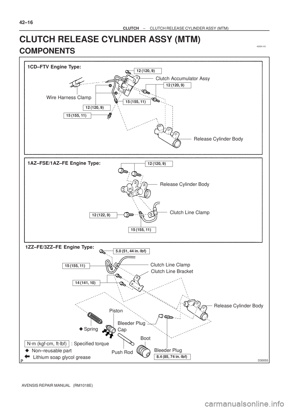
D30055Lithium soap glycol grease
N�m (kgf�cm, ft�lbf) : Specified torque
�Non±reusable part 1CD±FTV Engine Type:
Bleeder PlugRelease Cylinder Body
Piston
Push RodBoot Bleeder Plug
Cap
8.4 (85, 74 in.�lbf)
Wire Harness ClampClutch Accumulator Assy
Spring
1AZ±FSE/1AZ±FE Engine Type:
15 (155, 11)
12 (120, 9)
�
12 (120, 9)
Release Cylinder Body
12 (120, 9)
Release Cylinder Body
Clutch Line Clamp
Clutch Line Bracket
15 (155, 11)
12 (122, 9)
5.0 (51, 44 in.�lbf)1ZZ±FE/3ZZ±FE Engine Type:
15 (155, 11)Clutch Line Clamp
14 (141, 10)
15 (155, 11)
12 (120, 9)
42±16
± CLUTCHCLUTCH RELEASE CYLINDER ASSY (MTM)
AVENSIS REPAIR MANUAL (RM1018E)
CLUTCH RELEASE CYLINDER ASSY (MTM)
COMPONENTS
Page 119 of 1690

AVENSIS REPAIR MANUAL (RM1018E)
5. REMOVE CLUTCH RELEASE CYLINDER ASSY
(")
D30488
1ZZ±FE/3ZZ±FE Engine Type:
1AZ±FE/1AZ±FSE Engine Type:
D26804
42±18
± CLUTCHCLUTCH RELEASE CYLINDER ASSY (MTM)
AVENSIS REPAIR MANUAL (RM1018E)
5. REMOVE CLUTCH RELEASE CYLINDER ASSY
(EXCEPT 1CD±FTV ENGINE TYPE)
(a) 1ZZ±FE/3ZZ±FE Engine Type:
Remove the 3 bolts, clutch release cylinder assy, and
clutch line bracket.
(b) 1AZ±FE/1AZ±FSE Engine Type:
Remove the 3 bolts and clutch release cylinder assy.
6. REMOVE CLUTCH RELEASE CYLINDER ASSY
(1CD±FTV ENGINE TYPE)
(a) Using a 12 mm deep socket wrench, remove the 2 bolts
and clutch release cylinder assy.
7. REMOVE CLUTCH RELEASE CYLINDER KIT
(a) Remove the boot from the cylinder body.
(b) Remove the push rod from the cylinder body.
(c) Remove the piston from the cylinder body.
NOTICE:
Be careful not to damage the inside of the cylinder body.
(d) Remove the spring from the cylinder body.
(e) Remove the bleeder plug cap from the bleeder plug.
8. REMOVE RELEASE CYLINDER BLEEDER PLUG
9. INSTALL RELEASE CYLINDER BLEEDER PLUG
Torque: 8.3 N�m (85 kgf�cm, 73 in.�lbf)
Page 120 of 1690

(1)
(1)
(1)
(2) (2)
± CLUTCHCLUTCH RELEASE CYLINDER ASSY (MTM)
42±19
AVENSIS REPAIR MANUAL (RM1018E)
10. INSTAL")
CL0672
D26804
D30488
1ZZ±FE/3ZZ±FE Engine Type:
1AZ±FE/1AZ±FSE Engine Type:(1)
(1)
(1)
(1)
(2) (2)
± CLUTCHCLUTCH RELEASE CYLINDER ASSY (MTM)
42±19
AVENSIS REPAIR MANUAL (RM1018E)
10. INSTALL CLUTCH RELEASE CYLINDER KIT
(a) Install the bleeder plug cap to the bleeder plug.
(b) Install a new spring to the cylinder body.
(c) Coat the parts with lithium soap base glycol grease, as
shown in the illustration.
(d) Install the piston to the cylinder body.
NOTICE:
Be careful not to damage the inside of the cylinder body.
(e) Install the push rod to the cylinder body.
(f) Install the boot to the cylinder body.
11. INSTALL CLUTCH RELEASE CYLINDER ASSY
(1CD±FTV ENGINE TYPE)
(a) Using a 12 mm deep socket wrench, install the clutch re-
lease cylinder assy with the 2 bolts.
Torque: 12 N�m (120 kgf�cm, 9 ft�lbf)
12. INSTALL CLUTCH RELEASE CYLINDER ASSY
(EXCEPT 1CD±FTV ENGINE TYPE)
(a) 1ZZ±FE/3ZZ±FE Engine Type:
(1) Install the clutch release cylinder and clutch line
bracket with the 2 bolts.
Torque: 14 N�m (141 kgf�cm, 10 ft�lbf)
(2) Install the flexible hose tube with the bolt.
Torque: 5.0 N�m (51 kgf�cm, 44 in.�lbf)
(b) 1AZ±FE/1AZ±FSE Engine Type:
(1) Install the clutch release cylinder with the 2 bolts.
Torque: 12 N�m (120 kgf�cm, 9 ft�lbf)
(2) Install the flexible hose tube with the bolt.
Torque: 12 N�m (122 kgf�cm, 9 ft�lbf)
Page 121 of 1690
D30814
D30487
SST(s)
1ZZ±FE/3ZZ±FE Engine Type:
1AZ±FE/1AZ±FSE Engine Type:SST(s)
42±20
±
CLUTCH CLUTCH RELEASE CYLINDER ASSY (MTM)
AVENSIS REPAIR MANUAL (RM1018E)
13. INSTALL CLUTCH ACCUMULATOR ASSY (1CD±FTV ENGINE TYPE)
(a) Install the clutch accumulator assy with the 2 nuts and
bolt.
Torque: 12 N �m (120 kgf �cm, 9 ft �lbf)
(b) Using SST(s), connect the 2 flexible hose tubes. SST 09023±00100
Torque: 15 N �m (155 kgf �cm, 11 ft �lbf)
(c) Connect the wire harness clamp.
14. CONNECT CLUTCH RELEASE CYLINDER TO FLEXIBLE HOSE TUBE (EXCEPT 1CD±FTV ENGINE
TYPE)
(a) Using SST(s), connect the flexible hose tube. SST 09023±00100
Torque: 15 N �m (155 kgf �cm, 11 ft �lbf)
15.INSTALL AIR TUBE NO.1 (1CD±FTV ENGINE TYPE) (See page 14±286)
16. INSTALL BATTERY (1CD±FTV ENGINE TYPE)
17. BLEED CLUTCH PIPE LINE
(a) Fill the brake reservoir tank with the brake fluid and bleed clutch syst\
em. Torque: 8.3 N �m (85 kgf �cm, 73 in. �lbf)
18. CHECK CLUTCH FLUID LEAKAGE
Page 123 of 1690
4206H±01
D26321
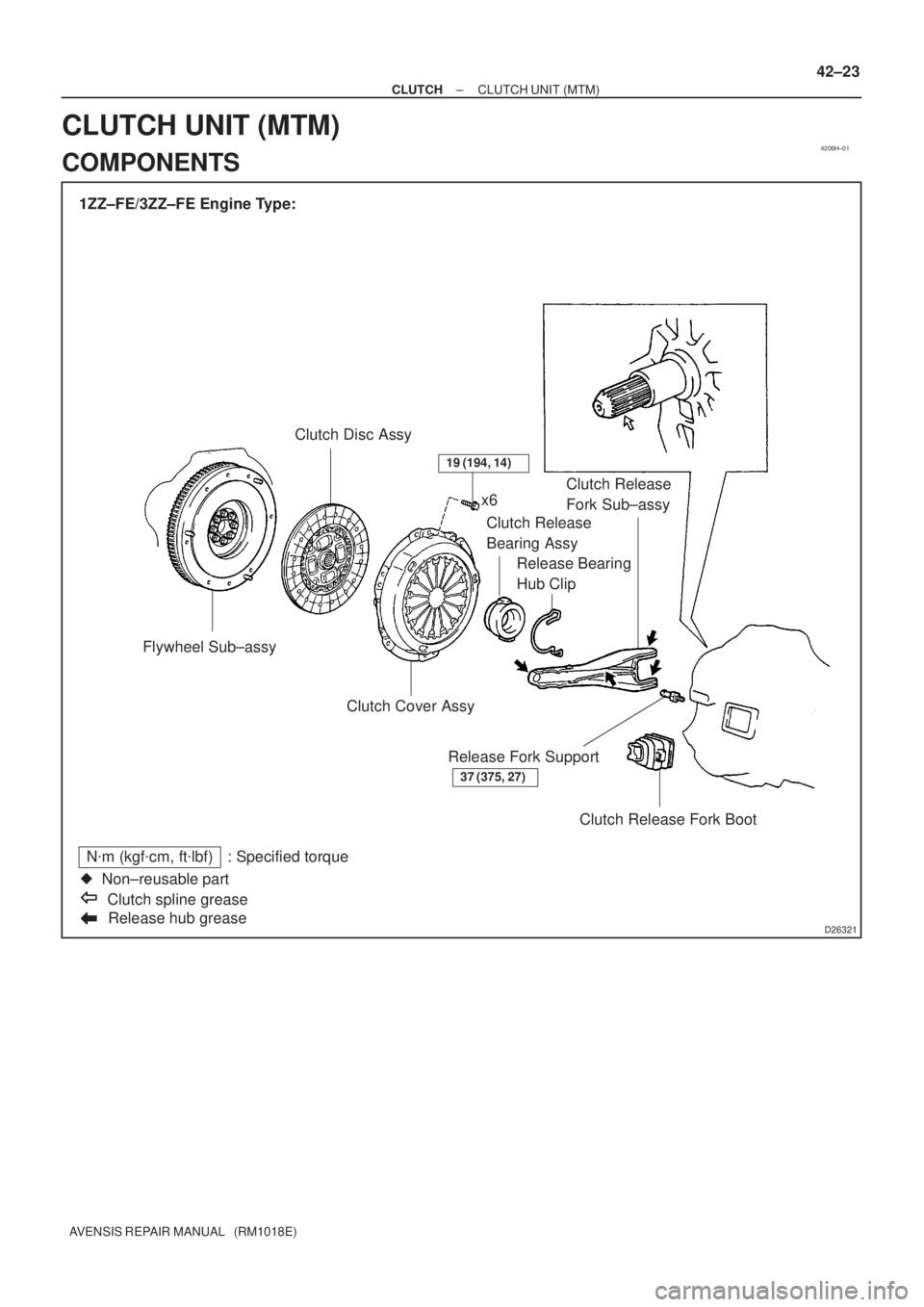
1ZZ±FE/3ZZ±FE Engine Type:
Flywheel Sub±assyClutch Disc Assy
Release hub grease
N�m (kgf�cm, ft�lbf) : Specified torque
�Non±reusable part
Clutch spline greasex6
Clutch Release
Bearing Assy
Release Bearing
Hub ClipClutch Release
Fork Sub±assy
Clutch Cover Assy
Clutch Release Fork Boot Release Fork Support
37 (375, 27)
19 (194, 14)
± CLUTCHCLUTCH UNIT (MTM)
42±23
AVENSIS REPAIR MANUAL (RM1018E)
CLUTCH UNIT (MTM)
COMPONENTS
Page 124 of 1690
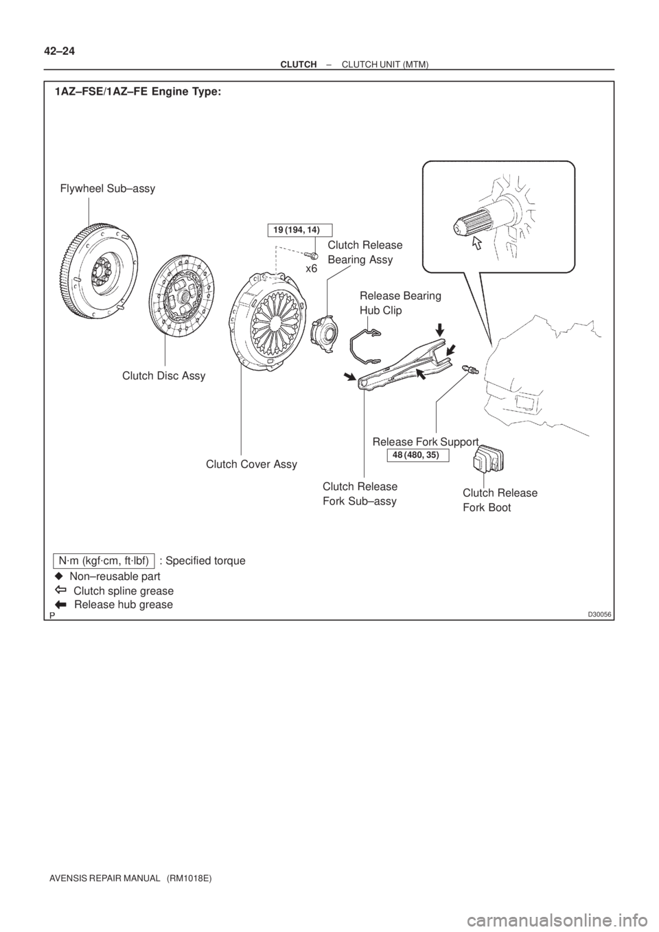
D30056Release hub grease
N�m (kgf�cm, ft�lbf) : Specified torque
�Non±reusable part
Clutch spline grease 1AZ±FSE/1AZ±FE Engine Type:
Flywheel Sub±assy
Clutch Disc Assy
Clutch Release
Fork Sub±assy Clutch Cover AssyRelease Bearing
Hub Clip Clutch Release
Bearing Assy
Release Fork Support
Clutch Release
Fork Boot
48 (480, 35)
19 (194, 14)
x6 42±24
± CLUTCHCLUTCH UNIT (MTM)
AVENSIS REPAIR MANUAL (RM1018E)

42±9
AVENSIS REPAIR MANUAL (RM1018E)
15. INSTALL CLUTCH PEDAL NO.1 CUSHIO")

1ZZ±FE/3ZZ±FE Engine Type:
1AZ±FE/1AZ±FSE Engine Type:SST(s)
42±20
±
CLUTCH CLUTCH RELEASE CYLINDER ASSY (MTM)
AVENSIS REPAIR MANUAL (RM1018E)
13. INSTALL CLUTCH ACCUMUL")