Page 45 of 1690
F45161
Brake Master
Cylinder Sub±assy
Clutch Master Cylinder AssyM/T Transaxle: Vacuum Tank Diesel Engine Type:
Brake Fulid Level
Switch Connector Accelerator Control
Cable Support
20 (204, 15)
19 (194, 14)
Clutch Reservoir
Hose M/T Transaxle: Brake Booster Assy� Brake Booster Gasket
Brake Master Cylinder
ClevisClip Clevis Pin
13 (130, 9)
15 (155, 11) *1
29 (296, 21) *2
15 (155, 11)
N�m (kgf�cm, ft�lbf)
: Specified torque
5.4 (55, 48 in.�lbf)
8.3 (85, 73 in.�lbf)
Wave Washer
Check Valve Grommet
15 (155, 11)
5.4 (55, 48 in.�lbf)
*1 w/ ABS:
*2 w/ VSC:
32±24
± BRAKEBRAKE BOOSTER ASSY (RHD)
AVENSIS REPAIR MANUAL (RM1018E)
Page 50 of 1690
C80805
C82119
C81275
C81274
F45367
± BRAKEBRAKE BOOSTER ASSY (RHD)
32±29
AVENSIS REPAIR MANUAL (RM1018E)
18. INSTALL BRAKE BOOSTER ASSY
(a) Install the clevis to the booster push rod.
(b) Install the brake booster assy with the 4 nuts.
Torque: 13 N�m (130 kgf�cm, 9 ft�lbf)
(c) Connect the vacuum hose to the check valve.
(d) Install the engine mounting bracket RH to the body with
the 3 bolts.
Torque: 52 N�m (530 kgf�cm, 39 ft�lbf)
(e) Install the bolt to the rear engine mounting bracket.
Torque: 87 N�m (887 kgf�cm, 64 ft�lbf)
(f) Install the bolt and nut to the front engine mounting brack-
et.
Torque: 52 N�m (530 kgf�cm, 39 ft�lbf)
(g) Install the 2 nuts to the engine mounting bracket RH.
Torque: 52 N�m (530 kgf�cm, 39 ft�lbf)
(h) Install the engine under cover.
(i) Connect the vacuum hose to the brake booster assy.
(j) Gasoline engine type:
Install the vacuum pipe with 2 bolts to the body.
Torque: 5.4 N�m (55 kgf�cm, 48 in.�lbf)
Page 51 of 1690
F45363Vacuum tank
F45362
F45361
C80802
32±30
± BRAKEBRAKE BOOSTER ASSY (RHD)
AVENSIS REPAIR MANUAL (RM1018E)
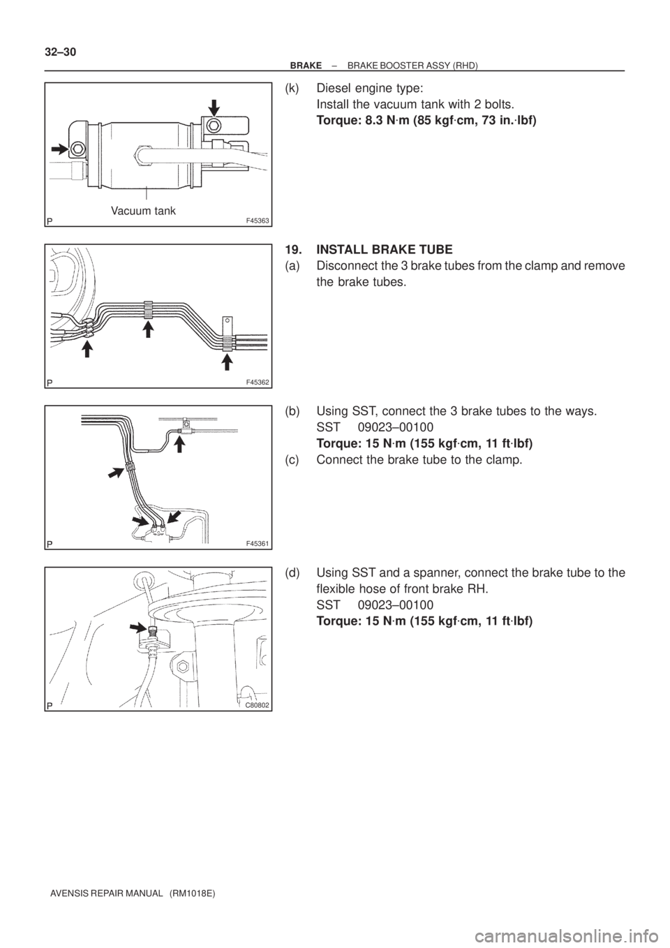
(k) Diesel engine type:
Install the vacuum tank with 2 bolts.
Torque: 8.3 N�m (85 kgf�cm, 73 in.�lbf)
19. INSTALL BRAKE TUBE
(a) Disconnect the 3 brake tubes from the clamp and remove
the brake tubes.
(b) Using SST, connect the 3 brake tubes to the ways.
SST 09023±00100
Torque: 15 N�m (155 kgf�cm, 11 ft�lbf)
(c) Connect the brake tube to the clamp.
(d) Using SST and a spanner, connect the brake tube to the
flexible hose of front brake RH.
SST 09023±00100
Torque: 15 N�m (155 kgf�cm, 11 ft�lbf)
Page 52 of 1690

F45057
w/o VSC:
w/ VSC:
To Master
Cylinder Rear
To
Master
Cylinder
Front
To Rear Wheel
RH
To Front Wheel LH
To Front Wheel RH
To Rear Wheel
LH
A
To
Master
Cylinder
FrontTo Master
Cylinder
Rear
To Rear
Wheel RH
To Front Wheel LHTo Front Wheel RH
To Rear
Wheel LH
AA
AA
BB
C80806
±
BRAKE BRAKE BOOSTER ASSY (RHD)
32±31
AVENSIS REPAIR MANUAL (RM1018E)
(e) w/o VSC:
Using SST, connect the 6 brake tubes to the brake actua-
tor, as shown in the illustration.
SST 09023±00100
Torque: 15 N �m (155 kgf �cm, 11 ft �lbf)
(f) w/ VSC: Using SST, connect the 6 brake tubes to the brake actua-
tor as shown in the illustration.
SST 09023±00100, 09023±38400
Torque:
A: 15 N �m (155 kgf �cm, 11 ft �lbf)
B: 29 N �m (296 kgf �cm, 21 ft �lbf)
(g) Install the brake tube clamps with the 2 bolts. Torque: 5.4 N �m (55 kgf �cm, 48 in. �lbf)
20. INSTALL FRONT WHEEL RH
21.INSTALL CYLINDER HEAD COVER SUB±ASSY (GASOLINE ENGINE TYPE) (See page 14±81)
22.INSTALL IGNITION COIL ASSY (GASOLINE ENGINE TYPE) (See page 14±81)
23.INSTALL INJECTOR ASSY (DIESEL ENGINE TYPE) (See page 14±318)
24.INSTALL CYLINDER HEAD COVER SUB±ASSY (DIESEL ENGINE TYPE) (See page 14±318)
25.INSTALL TIMING BELT NO.2 COVER (DIESEL ENGINE TYPE) (See page 14±307)
Page 55 of 1690
F42258
G24222
± BRAKEBRAKE FLUID
32±5
AVENSIS REPAIR MANUAL (RM1018E)
3. BLEED BRAKE LINE
(a) Connect the vinyl tube to the brake caliper.
(b) Depress the brake pedal several times, then loosen the
bleeder plug with the pedal depressed.
(c) At the point when the fluid stops, coming out tighten the
bleeder plug, then release the brake pedal.
(d) Repeat (b) and (c) until all the air in the fluid has been bled
out.
(e) Repeat the above procedure to bleed the air out of the
brake line for each wheel.
Torque: 10 N�m (102 kgf�cm, 7 ft.�lbf)
4. CHECK FLUID LEVEL IN RESERVOIR
(a) Check the fluid level and add fluid if necessary.
Fluid: SAE J1704 or FMVSS No. 116 DOT4
Page 56 of 1690
320W5±01
G24285
LHD Steering Position Type:
Charcoal Canister Assy
Brake Fluid Level
Switch Connector
Clutch Reservoir
Tube M/T Transaxle:Brake Booster Assy
Clip
Way
20 (204, 15)
15 (155, 11)
15 (155, 11)*1
29 (296, 21)*2
15 (155, 11)*1
29 (296, 21)*2
Brake Master
Cylinder Sub±assy
20 (204, 15)
Engin Room Relay Block
RHD Steering Position Type:Air Cleaner Cap Sub±assy
Brake Fluid Level
Switch ConnectorBrake Master
Cylinder Sub±assy
Clip
Accelerator Control
Cable Support
20 (204, 15)
*1
w/ ABS:*2 w/ VSC:N�m (kgf�cm, ft�lbf) : Specified torque
15 (155, 11)*1
29 (296, 21)*2
15 (155, 11)*1
29 (296, 21)*2
Clutch Reservoir
Tube M/T Transaxle:
Brake Booster Assy
5.4 (55, 48 in.�lbf)
Fuel Filter Assy Diesel Engin Type:
± BRAKEBRAKE MASTER CYLINDER SUB±ASSY
32±11
AVENSIS REPAIR MANUAL (RM1018E)
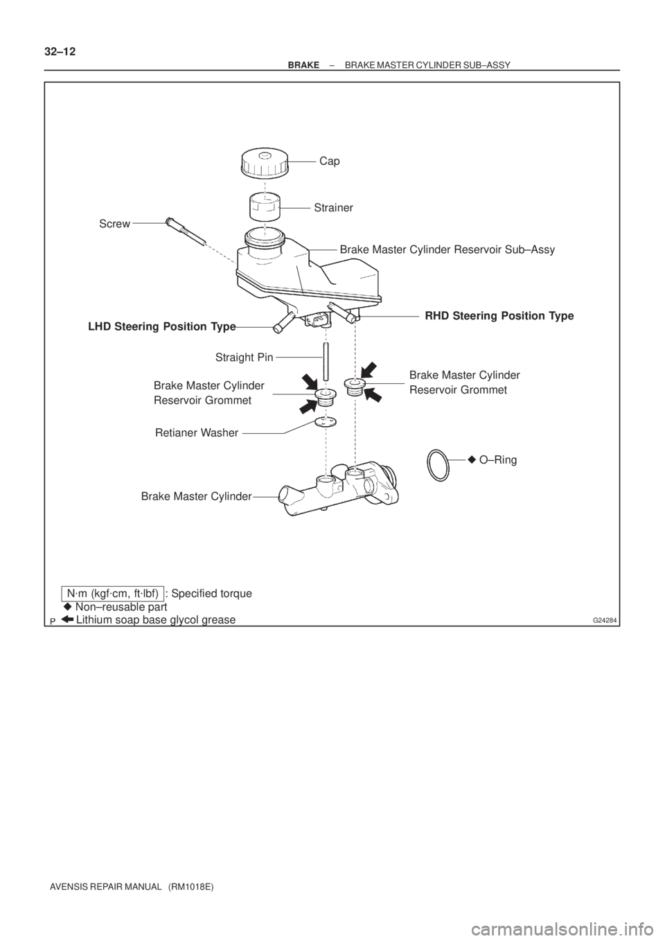
BRAKE MASTER CYLINDER SUB±ASSY
COMPONENTS
Page 57 of 1690
G24284
Cap
Strainer
Brake Master Cylinder Reservoir Sub±Assy
Brake Master Cylinder
Reservoir Grommet
Brake Master Cylinder
Straight Pin
Screw
Lithium soap base glycol grease � Non±reusable part
N�m (kgf�cm, ft�lbf) : Specified torque
Brake Master Cylinder
Reservoir Grommet LHD Steering Position TypeRHD Steering Position Type
� O±Ring
Retianer Washer
32±12
± BRAKEBRAKE MASTER CYLINDER SUB±ASSY
AVENSIS REPAIR MANUAL (RM1018E)
Page 60 of 1690

10. INSTALL BRAKE MASTER CYLINDER SUB±ASSY
(LHD STEERING POSITION TYPE)
(a) Install the ne")
F45393
G24217
G24218
F45394
± BRAKEBRAKE MASTER CYLINDER SUB±ASSY
32±15
AVENSIS REPAIR MANUAL (RM1018E)
10. INSTALL BRAKE MASTER CYLINDER SUB±ASSY
(LHD STEERING POSITION TYPE)
(a) Install the new O±ring from the brake master cylinder
sub±assy.
(b) Install the brake master cylinder sub±assy and way
bracket with the 2 nuts.
Torque: 20 N�m (204 kgf�cm, 15 ft�lbf)
(c) Using SST, connect the 2 brake lines to the way.
SST 09023±00100
Torque: 15 N�m (155 kgf�cm, 11 ft�lbf)
(d) w/o VSC:
Using SST, connect the 2 brake lines to the brake master
cylinder sub±assy.
SST 09023±00100
Torque: 15 N�m (155 kgf�cm, 11 ft�lbf)
(e) w/ VSC:
Using SST, connect the 2 brake lines to the brake master
cylinder sub±assy.
SST 09023±38400
Torque: 29 N�m (296 kgf�cm, 21 ft�lbf)
(f) M/T transaxle:
Slide the clip and connect the clutch reservoir tube.
(g) Connect the brake fluid level switch connector.
11. INSTALL BRAKE MASTER CYLINDER SUB±ASSY
(RHD STEERING POSITION TYPE)
(a) Install the new O±ring from the brake master cylinder
sub±assy.
(b) Install the brake master cylinder sub±assy and accelera-
tor control cable support with the 2 nuts.
Torque: 20 N�m (204 kgf�cm, 15 ft�lbf)

19 (")

32±29
AVENSIS REPAIR MANUAL (RM1018E)
18. INSTALL BRAKE BOOSTER ASSY
(a) Install the clevis to the booster push rod.
(b) Install")

3. BLEED BRAKE LINE
(a) Connect the vinyl tube to the brake caliper.
(b) Depress the brake pedal several times, then loosen th")

15 (155, 11)
15 (155")