Page 125 of 1690
D30057
1CD±FTV Engine Type:
Flywheel Sub±assyClutch Disc Assy
Clutch Release Fork Sub±assy Clutch Cover Assy
Release Bearing
Hub Clip Clutch Release
Bearing Assy
Release Fork Support
Clutch Release
Fork Boot
37 (375, 27)
19 (194, 14)
x6
Release hub grease
N�m (kgf�cm, ft�lbf) : Specified torque
�Non±reusable part
Clutch spline grease
± CLUTCHCLUTCH UNIT (MTM)
42±25
AVENSIS REPAIR MANUAL (RM1018E)
Page 128 of 1690

Q01060
D30059
1CD±FTV Engine Type: Others:
Flywheel Side
SST(s)
D26323
SST(s)
Matchmarks 7
1 (Temporally), 4
3
6
2.58
D00205
SST(s)
42±28
± CLUTCHCLUTCH UNIT (MTM)
AVENSIS REPAIR MANUAL (RM1018E)
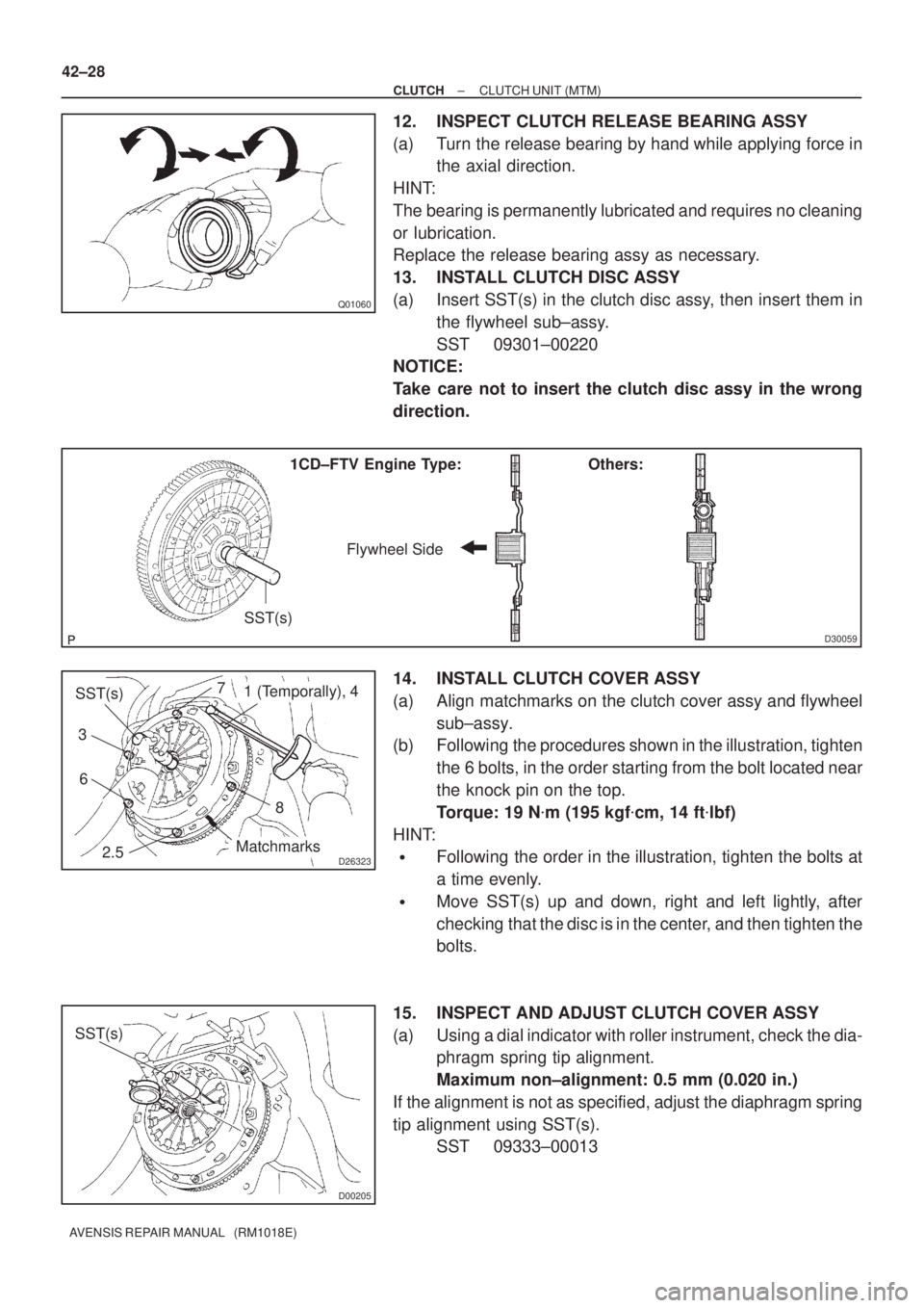
12. INSPECT CLUTCH RELEASE BEARING ASSY
(a) Turn the release bearing by hand while applying force in
the axial direction.
HINT:
The bearing is permanently lubricated and requires no cleaning
or lubrication.
Replace the release bearing assy as necessary.
13. INSTALL CLUTCH DISC ASSY
(a) Insert SST(s) in the clutch disc assy, then insert them in
the flywheel sub±assy.
SST 09301±00220
NOTICE:
Take care not to insert the clutch disc assy in the wrong
direction.
14. INSTALL CLUTCH COVER ASSY
(a) Align matchmarks on the clutch cover assy and flywheel
sub±assy.
(b) Following the procedures shown in the illustration, tighten
the 6 bolts, in the order starting from the bolt located near
the knock pin on the top.
Torque: 19 N�m (195 kgf�cm, 14 ft�lbf)
HINT:
�Following the order in the illustration, tighten the bolts at
a time evenly.
�Move SST(s) up and down, right and left lightly, after
checking that the disc is in the center, and then tighten the
bolts.
15. INSPECT AND ADJUST CLUTCH COVER ASSY
(a) Using a dial indicator with roller instrument, check the dia-
phragm spring tip alignment.
Maximum non±alignment: 0.5 mm (0.020 in.)
If the alignment is not as specified, adjust the diaphragm spring
tip alignment using SST(s).
SST 09333±00013
Page 129 of 1690

D26819
EXCEPT 1CD±FTV Engine Type:
1CD±FTV Engine Type:
Release Hub Grease
±
CLUTCH CLUTCH UNIT (MTM)
42±29
AVENSIS REPAIR MANUAL (RM1018E)
16. INSTALL RELEASE FORK SUPPORT
(a) Install the release fork support to the transaxle assy.
Torque:
1ZZ±FE/3ZZ±FE/1CD±FTV Engine Type: 37 N �m (375 kgf �cm, 27 ft �lbf)
1AZ±FSE/1AZ±FE Engine Type: 47 N �m (480 kgf �cm, 35 ft �lbf)
17. INSTALL RELEASE BEARING HUB CLIP
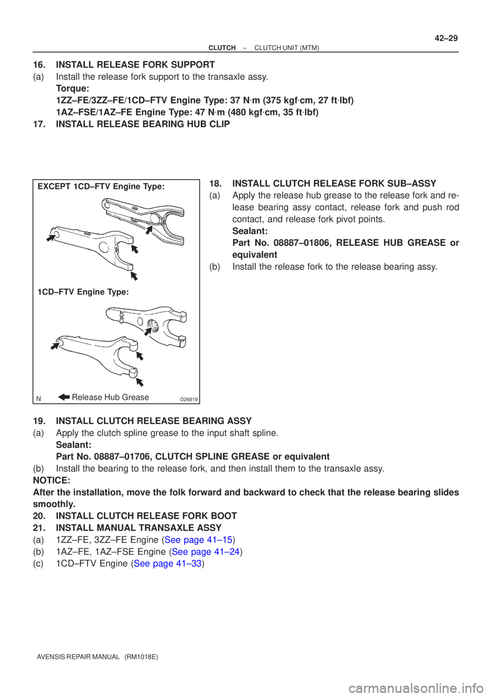
18. INSTALL CLUTCH RELEASE FORK SUB±ASSY
(a) Apply the release hub grease to the release fork and re-lease bearing assy contact, release fork and push rod
contact, and release fork pivot points.
Sealant:
Part No. 08887±01806, RELEASE HUB GREASE or
equivalent
(b) Install the release fork to the release bearing assy.
19. INSTALL CLUTCH RELEASE BEARING ASSY
(a) Apply the clutch spline grease to the input shaft spline. Sealant:
Part No. 08887±01706, CLUTCH SPLINE GREASE or equivalent
(b) Install the bearing to the release fork, and then install them to the tr\
ansaxle assy.
NOTICE:
After the installation, move the folk forward and backward to check that\
the release bearing slides
smoothly.
20. INSTALL CLUTCH RELEASE FORK BOOT
21. INSTALL MANUAL TRANSAXLE ASSY
(a)1ZZ±FE, 3ZZ±FE Engine (See page 41±15)
(b)1AZ±FE, 1AZ±FSE Engine (See page 41±24)
(c)1CD±FTV Engine (See page 41±33)
Page 130 of 1690
69067±02
B67410
± COMMUNICATION SYSTEMHIGH PITCHED HORN ASSY
69±5
AVENSIS REPAIR MANUAL (RM1018E)
HIGH PITCHED HORN ASSY
REPLACEMENT
1. REMOVE HIGH PITCHED HORN ASSY
(a) Disconnect the connector.
(b) Remove the bolt and horn.
2. INSTALL HIGH PITCHED HORN ASSY
(a) Place the stay onto the baffle part in the radiator support
upper, and then install the horn with the bolt.
Torque: 20 N�m (204 kgf�cm, 15 ft�lbf)
(b) Connect the connector.
Page 134 of 1690
69068±02
B67411
69±4
± COMMUNICATION SYSTEMLOW PITCHED HORN ASSY
AVENSIS REPAIR MANUAL (RM1018E)
LOW PITCHED HORN ASSY
REPLACEMENT
1. REMOVE LOW PITCHED HORN ASSY
(a) Disconnect the connector.
(b) Remove the bolt and horn.
2. INSTALL LOW PITCHED HORN ASSY
(a) Place the stay onto the baffle part in the radiator support
upper, and then install the horn with the bolt.
Torque: 20 N�m (204 kgf�cm, 15 ft�lbf)
(b) Connect the connector.
Page 145 of 1690
A79301
Upper Hook
Fan
Shroud
Radiator
16±12
±
COOLING RADIATOR ASSY(1ZZ±FE/3ZZ±FE)
AVENSIS REPAIR MANUAL (RM1018E)
10.INSTALL RADIATOR ASSY
(a)Align the 2 keyways of the fan shroud with the 2 keys lo- cated on the lower bottom of the radiator and fit them.
(b)Install the fan should to the radiator with the 2 upper hooks. You can hear ºclickº sounds when the hooks are
securely fitted.
(c)Install the 2 support radiator LWRs to the radiator.
(d)Install the radiator with the 2 bolts and 2 radiator support
uppers.
Torque: 19 N �m (194 kgf �cm, 14 ft �lbf)
(e)Install the relay block with the 2 bolts.
(f)Connect the fan connector and 2 harness clamps.
11.ADD ENGINE COOLANT (See page 16±7)
12.CHECK FOR ENGINE COOLANT LEAKS (See page 16±1)
Page 166 of 1690

160MD±01
A79169
Water Drain
Plug
Radiator Drain Plug
A63951
A
B 16±44
± COOLINGENGINE COOLANT (1CD±FTV)
AVENSIS REPAIR MANUAL (RM1018E)
ENGINE COOLANT (1CD±FTV)
REPLACEMENT
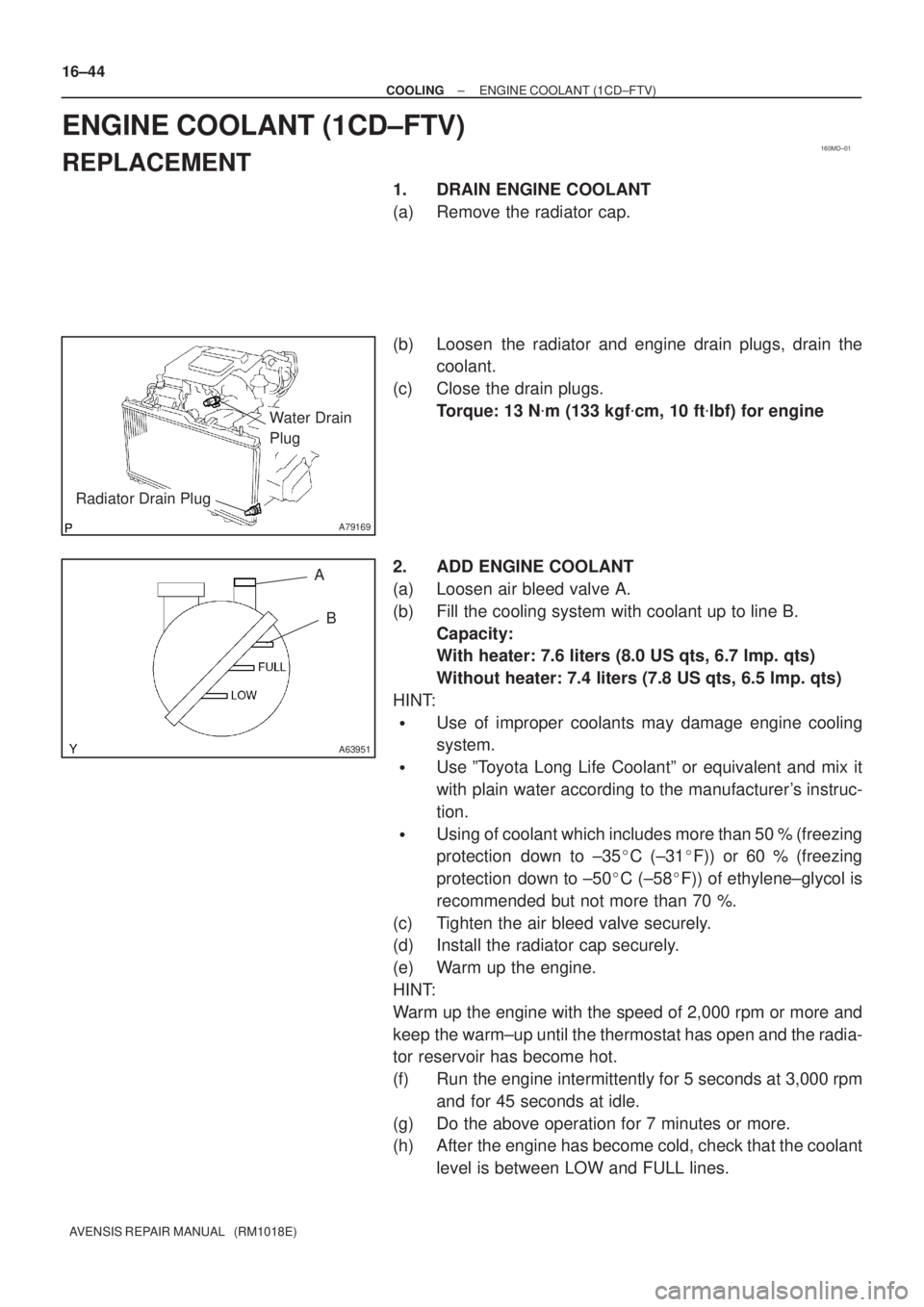
1. DRAIN ENGINE COOLANT
(a) Remove the radiator cap.
(b) Loosen the radiator and engine drain plugs, drain the
coolant.
(c) Close the drain plugs.
Torque: 13 N�m (133 kgf�cm, 10 ft�lbf) for engine
2. ADD ENGINE COOLANT
(a) Loosen air bleed valve A.
(b) Fill the cooling system with coolant up to line B.
Capacity:
With heater: 7.6 liters (8.0 US qts, 6.7 lmp. qts)
Without heater: 7.4 liters (7.8 US qts, 6.5 lmp. qts)
HINT:
�Use of improper coolants may damage engine cooling
system.
�Use ºToyota Long Life Coolantº or equivalent and mix it
with plain water according to the manufacturer's instruc-
tion.
�Using of coolant which includes more than 50 % (freezing
protection down to ±35�C (±31�F)) or 60 % (freezing
protection down to ±50�C (±58�F)) of ethylene±glycol is
recommended but not more than 70 %.
(c) Tighten the air bleed valve securely.
(d) Install the radiator cap securely.
(e) Warm up the engine.
HINT:
Warm up the engine with the speed of 2,000 rpm or more and
keep the warm±up until the thermostat has open and the radia-
tor reservoir has become hot.
(f) Run the engine intermittently for 5 seconds at 3,000 rpm
and for 45 seconds at idle.
(g) Do the above operation for 7 minutes or more.
(h) After the engine has become cold, check that the coolant
level is between LOW and FULL lines.
Page 168 of 1690

160MH±01
A64364
Radiator CapCylinder Block
Drain Cock Plug
Drain Pipe
Radiator
Drain Cock Plug
± COOLINGENGINE COOLANT (1ZZ±FE/3ZZ±FE)
16±7
AVENSIS REPAIR MANUAL (RM1018E)
ENGINE COOLANT (1ZZ±FE/3ZZ±FE)
REPLACEMENT
1. DRAIN ENGINE COOLANT
CAUTION:
To avoid the danger of being burned, do not remove the ra-
diator cap while the engine and radiator are still hot.
Thermal expansion will cause hot engine coolant and
steam to blow out from the radiator.
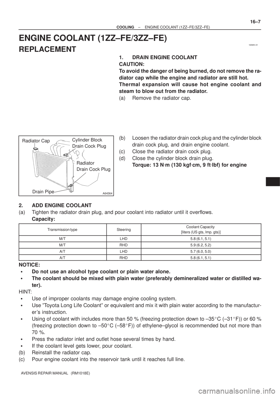
(a) Remove the radiator cap.
(b) Loosen the radiator drain cock plug and the cylinder block
drain cock plug, and drain engine coolant.
(c) Close the radiator drain cock plug.
(d) Close the cylinder block drain plug.
Torque: 13 N�m (130 kgf�cm, 9 ft�lbf) for engine
2. ADD ENGINE COOLANT
(a) Tighten the radiator drain plug, and pour coolant into radiator until it overflows.
Capacity:
Transmission typeSteeringCoolant Capacity
[liters (US gts, lmp. gts)]
M/TLHD5.8 (6.1, 5.1)
M/TRHD5.9 (6.2, 5.2)
A/TLHD5.7 (6.0, 5.0)
A/TRHD5.8 (6.1, 5.1)
NOTICE:
�Do not use an alcohol type coolant or plain water alone.
�The coolant should be mixed with plain water (preferably demineralized water or distilled wa-
ter).
HINT:
�Use of improper coolants may damage engine cooling system.
�Use ºToyota Long Life Coolantº or equivalent and mix it with plain water according to the manufactur-
er's instruction.
�Using of coolant with includes more than 50 % (freezing protection down to ±35�C (±31�F)) or 60 %
(freezing protection down to ±50�C (±58�F)) of ethylene±glycol is recommended but not more than
70 %.
�Press the radiator inlet and outlet hose several times by hand.
�If the coolant level gets lower, pour coolant.
(b) Reinstall the radiator cap.
(c) Pour engine coolant into the reservoir tank until it reaches full line.