Page 170 of 1690
160MX±01
16±24
±
COOLING RADIATOR ASSY(1AZ±FE)
AVENSIS REPAIR MANUAL (RM1018E)
RADIATOR ASSY(1AZ±FE)
REPLACEMENT
1.DRAIN COOLANT (See page 16±19)
2.REMOVE RADIATOR SUPPORT OPENING COVER
3.REMOVE ENGINE ROOM COVER SIDE
4.REMOVE ENGINE UNDER COVER RH
5.DISCONNECT RADIATOR HOSE INLET
6.DISCONNECT RADIATOR HOSE OUTLET
7.REMOVE RADIATOR SUPPORT UPPER
(a)Disconnect the fan w/ motor wire harness, connector and the horn connect\
or.
(b)Remove 4 bolts, the nut and the radiator support.
8.REMOVE RADIATOR ASSY
(a)Remove 2 upper support, and radiator assembly
9.REMOVE RADIATOR SUPPORT LOWER
10.REMOVE FAN ASSY W/MOTOR
(a)Remove 6 bolts and fan w/motor.
11.INSTALL FAN ASSY W/MOTOR
12.INSTALL RADIATOR SUPPORT LOWER
13.INSTALL RADIATOR ASSY
14.INSTALL RADIATOR SUPPORT UPPER
(a)Install radiator support with 2 bolts. Torque: 19 N �m (194 kgf �cm,14 ft �lbf)
15.ADD COOLANT (See page 16±19)
16.INSPECT CHECK FOR ENGINE COOLANT LEAKS (See page 16±13)
Page 171 of 1690
160MS±01
16±36
±
COOLING RADIATOR ASSY(1AZ±FSE)
AVENSIS REPAIR MANUAL (RM1018E)
RADIATOR ASSY(1AZ±FSE)
REPLACEMENT
1.DRAIN COOLANT (See page 16±31)
2.REMOVE RADIATOR SUPPORT OPENING COVER
3.REMOVE ENGINE ROOM COVER SIDE
4.REMOVE ENGINE UNDER COVER RH
5.DISCONNECT RADIATOR HOSE INLET
6.DISCONNECT RADIATOR HOSE OUTLET
7.REMOVE RADIATOR SUPPORT UPPER
(a)Disconnect the fan w/ motor wire harness, connector and the horn connect\
or.
(b)Remove 4 bolts, the nut and the radiator support.
8.REMOVE RADIATOR ASSY
(a)Remove 2 upper support, and radiator assembly
9.REMOVE RADIATOR SUPPORT LOWER
10.REMOVE FAN ASSY W/MOTOR
(a)Remove 6 bolts and fan w/motor.
11.INSTALL FAN ASSY W/MOTOR
12.INSTALL RADIATOR SUPPORT LOWER
13.INSTALL RADIATOR ASSY
14.INSTALL RADIATOR SUPPORT UPPER
(a)Install radiator support with 2 bolts. Torque: 19 N �m (194 kgf �cm,14 ft �lbf)
15.ADD COOLANT (See page 16±31)
16.INSPECT CHECK FOR ENGINE COOLANT LEAKS (See page 16±25)
Page 172 of 1690

16±51
AVENSIS REPAIR MANUAL (RM1018E)
RADIATOR ASSY(1CD±FTV)
REPLACEMENT
1.DRAIN ENGINE COOLANT(See page 16±44)
2.REMOVE RADIATOR SUPPORT OPENING COVE")
160MG±01
±
COOLING RADIATOR ASSY(1CD±FTV)
16±51
AVENSIS REPAIR MANUAL (RM1018E)
RADIATOR ASSY(1CD±FTV)
REPLACEMENT
1.DRAIN ENGINE COOLANT(See page 16±44)
2.REMOVE RADIATOR SUPPORT OPENING COVER
3.REMOVE ENGINE ROOM COVER SIDE
4.REMOVE RADIATOR RESERVE TANK ASSY(See page 16±50)
5.DISCONNECT RADIATOR HOSE INLET
6.DISCONNECT RADIATOR HOSE OUTLET
7.REMOVE RADIATOR ASSY
(a)Remove the 2 bolts and separate the relay box.
(b)Remove the 2 upper support and radiator assy.
8.REMOVE RADIATOR SUPPORT LOWER
9.REMOVE FAN ASSY W/MOTOR
(a)Remove the 2 bolts and the fan w/motor.
10.INSTALL FAN ASSY W/MOTOR
Torque: 7.5 N �m (76 kgf �cm, 66 in. �lbf)
11.INSTALL RADIATOR ASSY
(a)Install the 2 upper support and the radiator assembly to the vehicle. Torque: 19 N �m (194 kgf �cm, 14 ft �lbf)
(b)Install the 2 bolts and the relay box.
Torque: 5.3 N �m (54 kgf �cm, 47 in. �lbf)
12.INSTALL RADIATOR RESERVE TANK ASSY(See page 16±50)
13.ADD ENGINE COOLANT(See page 16±44)
14.CHECK FOR ENGINE COOLANT LEAKS(See page 16±44)
Page 174 of 1690
A79301
Upper Hook
Fan
Shroud
Radiator
16±12
±
COOLING RADIATOR ASSY(1ZZ±FE/3ZZ±FE)
AVENSIS REPAIR MANUAL (RM1018E)
10.INSTALL RADIATOR ASSY
(a)Align the 2 keyways of the fan shroud with the 2 keys lo- cated on the lower bottom of the radiator and fit them.
(b)Install the fan should to the radiator with the 2 upper hooks. You can hear ºclickº sounds when the hooks are
securely fitted.
(c)Install the 2 support radiator LWRs to the radiator.
(d)Install the radiator with the 2 bolts and 2 radiator support
uppers.
Torque: 19 N �m (194 kgf �cm, 14 ft �lbf)
(e)Install the relay block with the 2 bolts.
(f)Connect the fan connector and 2 harness clamps.
11.ADD ENGINE COOLANT (See page 16±7)
12.CHECK FOR ENGINE COOLANT LEAKS (See page 16±1)
Page 175 of 1690

16±35
AVENSIS REPAIR MANUAL (RM1018E)
THERMOSTAT(1AZ±FSE)
REPLACEMENT
1.DRAIN COOLANT (See page 16±31)
2.REMOVE RADIATOR SUPPORT OPE")
160MQ±01
A56451
A77424
10�10�
±
COOLING THERMOSTAT(1AZ±FSE)
16±35
AVENSIS REPAIR MANUAL (RM1018E)
THERMOSTAT(1AZ±FSE)
REPLACEMENT
1.DRAIN COOLANT (See page 16±31)
2.REMOVE RADIATOR SUPPORT OPENING COVER
3.REMOVE ENGINE ROOM COVER SIDE
4.REMOVE ENGINE UNDER COVER RH
5.REMOVE FAN AND GENERATOR V BELT (See page 14±185)
SST09249±63010
6.REMOVE GENERATOR ASSY (See page 19±20)
7.REMOVE WATER INLET
(a)Remove 2 nuts, and disconnect the water inlet from thecylinder block.
8.REMOVE THERMOSTAT 9.INSTALL THERMOSTAT
(a)Install a new gasket to the thermostat.
(b)Install the thermostat with the jiggle valve upward.
HINT:
The jiggle valve may be set within 10� on either side of the pre-
scribed position.
10.INSTALL WATER INLET
(a)Install the water inlet with 2 nuts. Torque: 9.0 N �m (92 kgf �cm,7 in. �lbf)
11.INSTALL GENERATOR ASSY (See page 19±20)
12.INSTALL FAN AND GENERATOR V BELT (See page 14±185) SST 09249±63010
13.ADD COOLANT (See page 16±31)
14.INSPECT CHECK FOR ENGINE COOLANT LEAKS(See page 16±25)
Page 176 of 1690
160MF±01
A79171
A79172
10�10�
16±50
±
COOLING THERMOSTAT(1CD±FTV)
AVENSIS REPAIR MANUAL (RM1018E)
THERMOSTAT(1CD±FTV)
REPLACEMENT
1.REMOVE RADIATOR SUPPORT OPENING COVER
2.REMOVE ENGINE ROOM COVER SIDE
3.DRAIN ENGINE COOLANT(See page 16±44)
4.REMOVE RADIATOR RESERVE TANK ASSY
(a)Disconnect the water by±pass hose No. 1 and water by±pass hose No.\
2.
(b)Remove the 2 bolts and the reserve tank assembly.
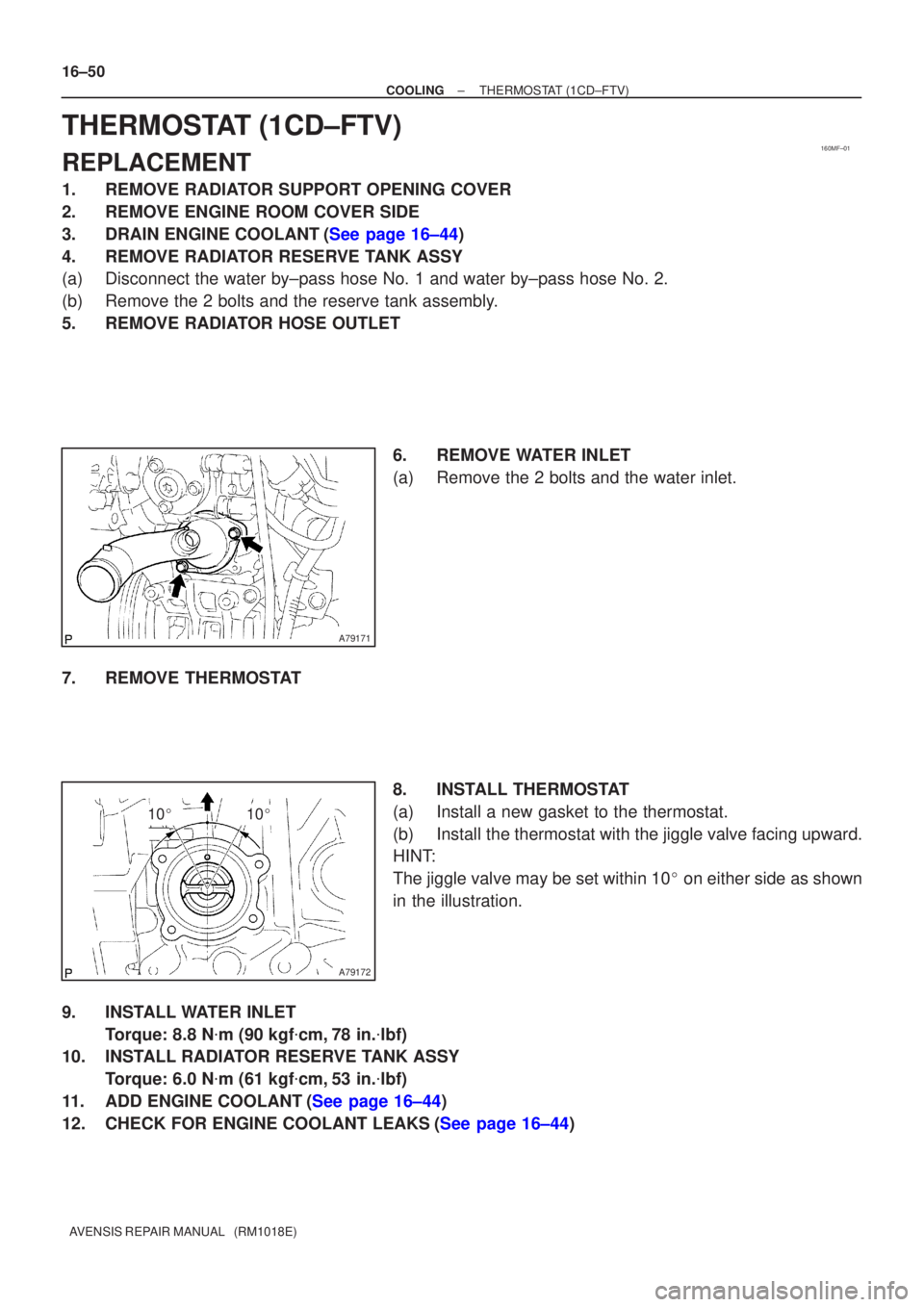
5.REMOVE RADIATOR HOSE OUTLET 6.REMOVE WATER INLET
(a)Remove the 2 bolts and the water inlet.
7.REMOVE THERMOSTAT 8.INSTALL THERMOSTAT
(a)Install a new gasket to the thermostat.
(b)Install the thermostat with the jiggle valve facing upward.
HINT:
The jiggle valve may be set within 10� on either side as shown
in the illustration.
9.INSTALL WATER INLET Torque: 8.8 N �m (90 kgf �cm,78 in. �lbf)
10.INSTALL RADIATOR RESERVE TANK ASSY
Torque: 6.0 N �m (61 kgf �cm,53 in. �lbf)
11.ADD ENGINE COOLANT(See page 16±44)
12.CHECK FOR ENGINE COOLANT LEAKS(See page 16±44)
Page 177 of 1690
160MJ±01
A62118
10�10�
16±10
±
COOLING THERMOSTAT(1ZZ±FE/3ZZ±FE)
AVENSIS REPAIR MANUAL (RM1018E)
THERMOSTAT(1ZZ±FE/3ZZ±FE)
REPLACEMENT
1.REMOVE RADIATOR SUPPORT OPENING COVER (See page 14±27)
2.ENGINE ROOM COVER SIDE (See page 14±27)
3.REMOVE ENGINE UNDER COVER SUB±ASSY NO.1 (See page 14±27)
4.DRAIN ENGINE COOLANT (See page 16±1)
5.REMOVE FAN AND GENERATOR V BELT (See page 14±5)
6.REMOVE GENERATOR ASSY (See page 19±7)
7.REMOVE WATER INLET
(a)Remove the 2 nuts and the water inlet.
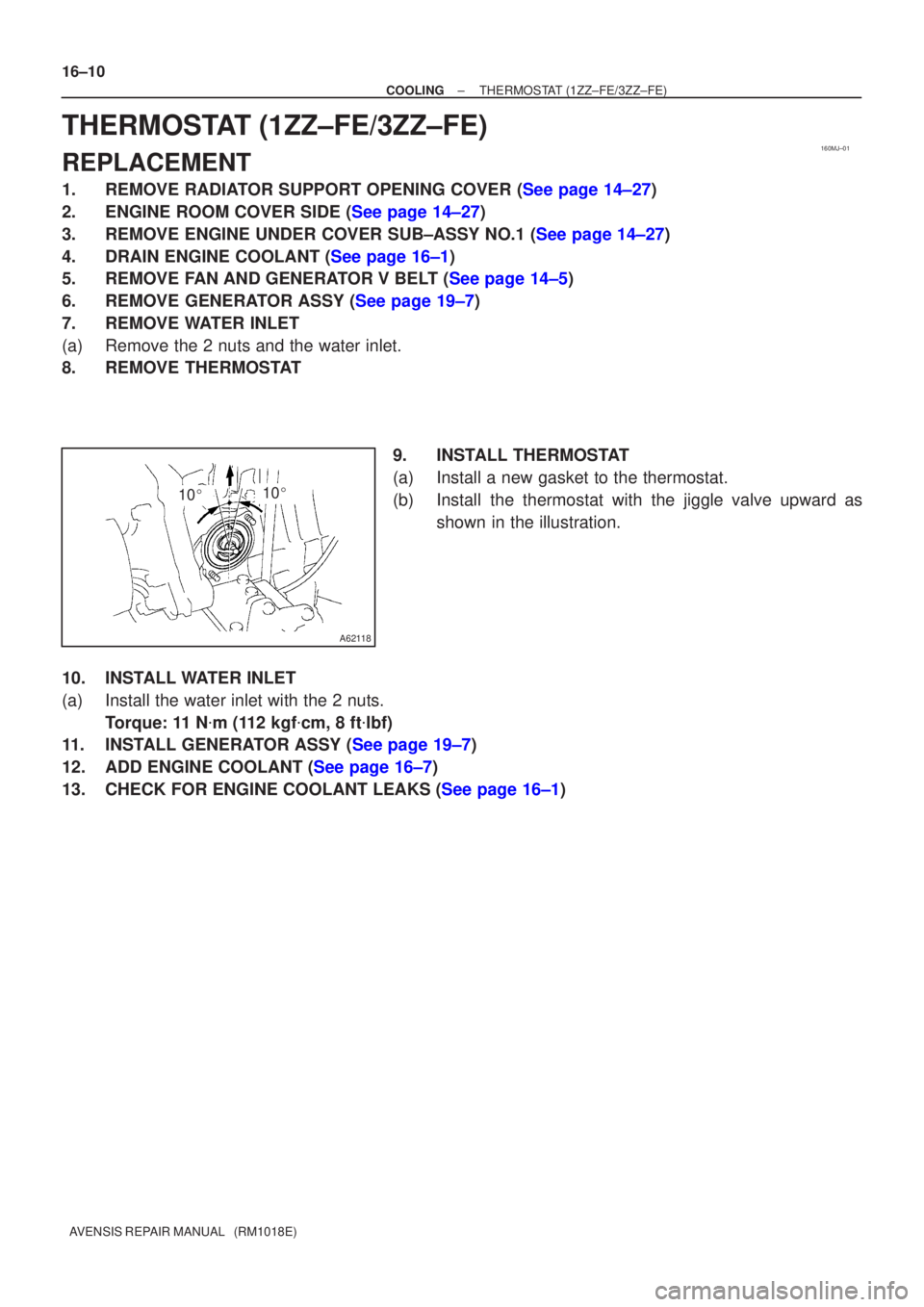
8.REMOVE THERMOSTAT 9.INSTALL THERMOSTAT
(a)Install a new gasket to the thermostat.
(b)Install the thermostat with the jiggle valve upward asshown in the illustration.
10.INSTALL WATER INLET
(a)Install the water inlet with the 2 nuts. Torque: 11 N �m (112 kgf �cm, 8 ft �lbf)
11.INSTALL GENERATOR ASSY (See page 19±7)
12.ADD ENGINE COOLANT (See page 16±7)
13.CHECK FOR ENGINE COOLANT LEAKS (See page 16±1)
Page 178 of 1690

16±23
AVENSIS REPAIR MANUAL (RM1018E)
THERMOSTAT(1AZ±FE)
REPLACEMENT
1.DRAIN COOLANT(See page 16±19)
2.REMOVE RADIATOR SUPPORT OPENIN")
160MT±01
A56451
A77424
10�10�
±
COOLING THERMOSTAT(1AZ±FE)
16±23
AVENSIS REPAIR MANUAL (RM1018E)
THERMOSTAT(1AZ±FE)
REPLACEMENT
1.DRAIN COOLANT(See page 16±19)
2.REMOVE RADIATOR SUPPORT OPENING COVER
3.REMOVE ENGINE ROOM COVER SIDE
4.REMOVE ENGINE UNDER COVER RH
5.REMOVE FAN AND GENERATOR V BELT (See page 14±105)
SST09249±63010
6.REMOVE GENERATOR ASSY (See page 19±20)
7.REMOVE WATER INLET
(a)Remove 2 nuts, and disconnect the water inlet from thecylinder block.
8.REMOVE THERMOSTAT 9.INSTALL THERMOSTAT
(a)Install a new gasket to the thermostat.
(b)Install the thermostat with the jiggle valve upward.
HINT:
The jiggle valve may be set within 10� on either side of the pre-
scribed position.
10.INSTALL WATER INLET
(a)Install the water inlet with 2 nuts. Torque: 9.0 N �m (92 kgf �cm,7 in. �lbf)
11.INSTALL GENERATOR ASSY (See page 19±20)
12.INSTALL FAN AND GENERATOR V BELT (See page 14±105) SST 09249±63010
13.ADD COOLANT (See page 16±19)
14.INSPECT CHECK FOR ENGINE COOLANT LEAKS (See page 16±13)

AVENSIS REPAIR MANUAL (RM1018E)
RADIATOR ASSY(1AZ±FE)
REPLACEMENT
1.DRAIN COOLANT (See page 16±19)
2.REMOVE RADIATOR SUPPORT OPENING COVER
3.REMO")

AVENSIS REPAIR MANUAL (RM1018E)
RADIATOR ASSY(1AZ±FSE)
REPLACEMENT
1.DRAIN COOLANT (See page 16±31)
2.REMOVE RADIATOR SUPPORT OPENING COVER
3.RE")

AVENSIS REPAIR MANUAL (RM1018E)
10.INSTALL RADIATOR ASSY
(a)Align the 2 keyways of the fan shroud with the 2 k")