Page 819 of 1690

110U8±01
A79143
SST
11±60
±
FUEL INJECTOR ASSY(1CD±FTV)
AVENSIS REPAIR MANUAL (RM1018E)
REPLACEMENT
HINT:
Each injector assembly has a characteristic fuel injecting behavior. The ECM stores compensation codes
which are used to optimize fuel injection for the injectors. When replacing t\
he injector assembly, a compensa-
tion code for the new injector assembly must be set to the ECM.
1.REMOVE VACUUM RESERVOIR SUB±ASSY
(a)Disconnect the 2 vacuum hoses and the connector.
(b)Remove the 2 bolts and the vacuum reservoir.
2.REMOVE RADIATOR SUPPORT OPENING COVER
3.REMOVE ENGINE COVER NO.1
(a)Remove the 5 nuts and the engine cover.
4.REMOVE AIR CLEANER ASSY
(a)Disconnect the connector.
(b)Remove the air cleaner cap with the air cleaner hose.
(c)Remove the air cleaner filter element.
(d)Remove the 3 bolts and the air cleaner case.
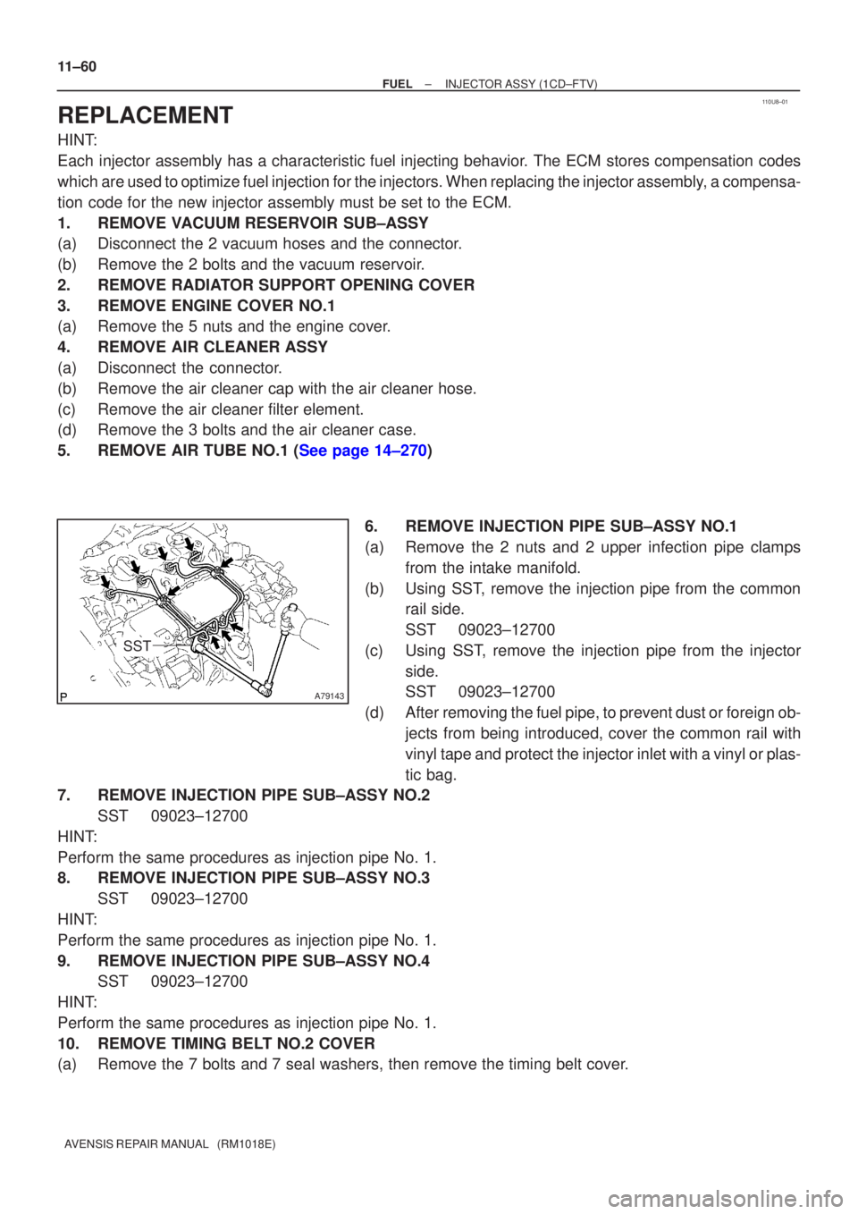
5.REMOVE AIR TUBE NO.1 (See page 14±270) 6. REMOVE INJECTION PIPE SUB±ASSY NO.1
(a) Remove the 2 nuts and 2 upper infection pipe clampsfrom the intake manifold.
(b) Using SST, remove the injection pipe from the common rail side.
SST 09023±12700
(c) Using SST, remove the injection pipe from the injector side.
SST 09023±12700
(d) After removing the fuel pipe, to prevent dust or foreign ob- jects from being introduced, cover the common rail with
vinyl tape and protect the injector inlet with a vinyl or plas-
tic bag.
7. REMOVE INJECTION PIPE SUB±ASSY NO.2
SST 09023±12700
HINT:
Perform the same procedures as injection pipe No. 1.
8. REMOVE INJECTION PIPE SUB±ASSY NO.3 SST 09023±12700
HINT:
Perform the same procedures as injection pipe No. 1.
9. REMOVE INJECTION PIPE SUB±ASSY NO.4 SST 09023±12700
HINT:
Perform the same procedures as injection pipe No. 1.
10. REMOVE TIMING BELT NO.2 COVER
(a) Remove the 7 bolts and 7 seal washers, then remove the timing belt cover\
.
Page 860 of 1690
550YS±01
I35345Claw
I35346
I35347
I35348
55±100
±
HEATER & AIR CONDITIONER HEATER ASSY
AVENSIS REPAIR MANUAL (RM1018E)
HEATER ASSY
REPLACEMENT
1.REMOVE AIR CLEANER ASSY (See page 11±82)
2.REMOVE FUEL FILTER ASSY (See page 11±82) 3. REMOVE AIR DUCT NO.3
(a) Release the claw fitting and remove the bolt and the en-gine room relay No.2 block.
(b) Remove the clip and the air duct No.3.
4. DISCONNECT HEATER INLET WATER HOSE
(a) Using pliers, grip the claws of the clip and slide the clip to disconnect the heater inlet water hose.
HINT:
Prepare a support plate and waste to catch the leaked coolant.
5. DISCONNECT HEATER WATER INLET HOSE A
(a) Using pliers, grip the claws of the clip and slide the clip to disconnect the heater inlet water hose A.
HINT:
Prepare a support plate and waste to catch the leaked coolant.
Page 861 of 1690
I35349
I35350
I35350
I35349
±
HEATER & AIR CONDITIONER HEATER ASSY
55±101
AVENSIS REPAIR MANUAL (RM1018E)
6. REMOVE HEATER ASSY
(a) Using pliers, grip the claws of the clip and slide the clip to
disconnect the heater fuel hose.
HINT:
Prepare a support plate and waste to catch the leaked fuel.
(b) Disconnect the connector.
(c) Remove the 2 bolts and the heater assy.
7. INSTALL HEATER ASSY
(a) Install the heater assy with the 2 bolts. Torque: 7.5 N �m (76 kgf �cm, 66 in. �lbf)
(b) Connect the connector.
(c) Install the heater fuel hose.
HINT:
Prepare a support plate and waste to catch the leaked fuel.
8.INSTALL FUEL FILTER ASSY (See page 11±82)
9.INSTALL AIR CLEANER ASSY (See page 11±82)
10.ADD ENGINE COOLANT (See page 16±44)
11.CHECK FOR ENGINE COOLANT LEAKS (See page 16±37)
12.CHECK FUEL LEAK (See page 11±56)
Page 968 of 1690
A79440
Union To Connector Tube Hose
Fuel Filter Assy Vacuum Reservoir Sub±assy
43 (440, 32)
43 (440, 32)
� Gasket
� GasketCompression Spring
Floor Panel Brace Front Exhaust Pipe Assy Front
Compression Spring
N´m (kgf´cm, ft´lbf)
: Specified torque
� Non±reusable part
Intercooler Air Hose
� Gasket
7.5 (76, 66 in.�lbf)
Exhaust Pipe Assy
30 (302, 22)
7.5 (76, 66 in.�lbf)
Heater Bracket
Heater Pump Assy25 (255, 18)
25 (255, 18)
7.5 (76, 66 in.�lbf)
18 (178, 13)
7.5 (76, 66 in.�lbf)
w/ Cold Area:
w/ Cold Area:
w/ Cold Area:
8.3 (85, 73 in.�lbf)
Air Tube No. 1
± INTAKETURBOCHARGER SUB±ASSY (1CD±FTV)
13±9
AVENSIS REPAIR MANUAL (RM1018E)
Page 970 of 1690
1306Z±01
A79155
A80093
A79158
±
INTAKE TURBOCHARGER SUB±ASSY(1CD±FTV)
13±11
AVENSIS REPAIR MANUAL (RM1018E)
REPLACEMENT
1.REMOVE ENGINE UNDER COVER SUB±ASSY NO.1
2.DRAIN ENGINE COOLANT(See page 16±44)
3.REMOVE RADIATOR SUPPORT OPENING COVER
4.REMOVE ENGINE COVER NO.1
(a)Remove the 5 nuts and the engine cover.
5.REMOVE VACUUM RESERVOIR SUB±ASSY
(a)Disconnect the 2 vacuum hoses and the connector.
(b)Remove the 2 bolts and the vacuum reservoir.
6.REMOVE AIR CLEANER ASSY
(a)Disconnect the PCV hose and the connector.
(b)Remove the air cleaner cap with the air cleaner hose.
(c)Remove the air cleaner filter element.
(d)Remove the 3 bolts and the air cleaner case. 7.REMOVE INTERCOOLER AIR HOSE
(a)Remove the 3 bolts and nut, separate the air tube No.1.
(b)Loosen the hose clamp bolts and remove the air hoseNo.1.
8.REMOVE FUEL FILTER ASSY(See page 11±82) 9. SEPARATE HEATER PUMP ASSY (W/ COLD AREA)
(a) Remove the nut and disconnect the connector.
(b) Separate the heater pump.
Page 975 of 1690

������������A80106
A
A
B
B
A79163
13±16
±
INTAKE TURBOCHARGER SUB±ASSY(1CD±FTV)
AVENSIS REPAIR MANUAL (RM1018E)
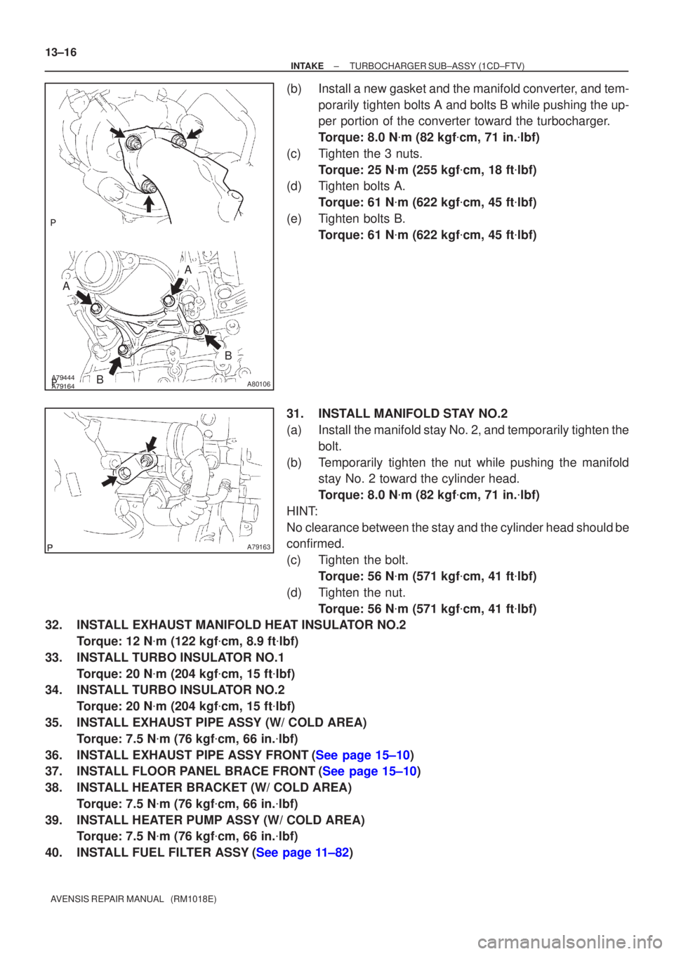
(b)Install a new gasket and the manifold converter, and tem- porarily tighten bolts A and bolts B while pushing the up-
per portion of the converter toward the turbocharger.
Torque: 8.0 N �m (82 kgf �cm, 71 in. �lbf)
(c)Tighten the 3 nuts. Torque: 25 N �m (255 kgf �cm, 18 ft �lbf)
(d)Tighten bolts A.
Torque: 61 N �m (622 kgf �cm, 45 ft �lbf)
(e)Tighten bolts B. Torque: 61 N �m (622 kgf �cm, 45 ft �lbf)
31.INSTALL MANIFOLD STAY NO.2
(a)Install the manifold stay No. 2, and temporarily tighten the bolt.
(b)Temporarily tighten the nut while pushing the manifold stay No. 2 toward the cylinder head.
Torque: 8.0 N �m (82 kgf �cm, 71 in. �lbf)
HINT:
No clearance between the stay and the cylinder head should be
confirmed.
(c)Tighten the bolt. Torque: 56 N �m (571 kgf �cm, 41 ft �lbf)
(d)Tighten the nut. Torque: 56 N �m (571 kgf �cm, 41 ft �lbf)
32.INSTALL EXHAUST MANIFOLD HEAT INSULATOR NO.2
Torque: 12 N �m (122 kgf �cm, 8.9 ft �lbf)
33.INSTALL TURBO INSULATOR NO.1 Torque: 20 N �m (204 kgf �cm, 15 ft �lbf)
34.INSTALL TURBO INSULATOR NO.2
Torque: 20 N �m (204 kgf �cm, 15 ft �lbf)
35.INSTALL EXHAUST PIPE ASSY (W/ COLD AREA) Torque: 7.5 N �m (76 kgf �cm, 66 in. �lbf)
36.INSTALL EXHAUST PIPE ASSY FRONT(See page 15±10)
37.INSTALL FLOOR PANEL BRACE FRONT(See page 15±10)
38. INSTALL HEATER BRACKET (W/ COLD AREA) Torque: 7.5 N �m (76 kgf �cm, 66 in. �lbf)
39. INSTALL HEATER PUMP ASSY (W/ COLD AREA) Torque: 7.5 N �m (76 kgf �cm, 66 in. �lbf)
40.INSTALL FUEL FILTER ASSY(See page 11±82)
Page 1008 of 1690

D01556
WRONG
D01563
01±16
± INTRODUCTIONREPAIR INSTRUCTION
AVENSIS REPAIR MANUAL (RM1018E)
(±) terminal cable is disconnected. If necessary, be
sure to initialize the system.
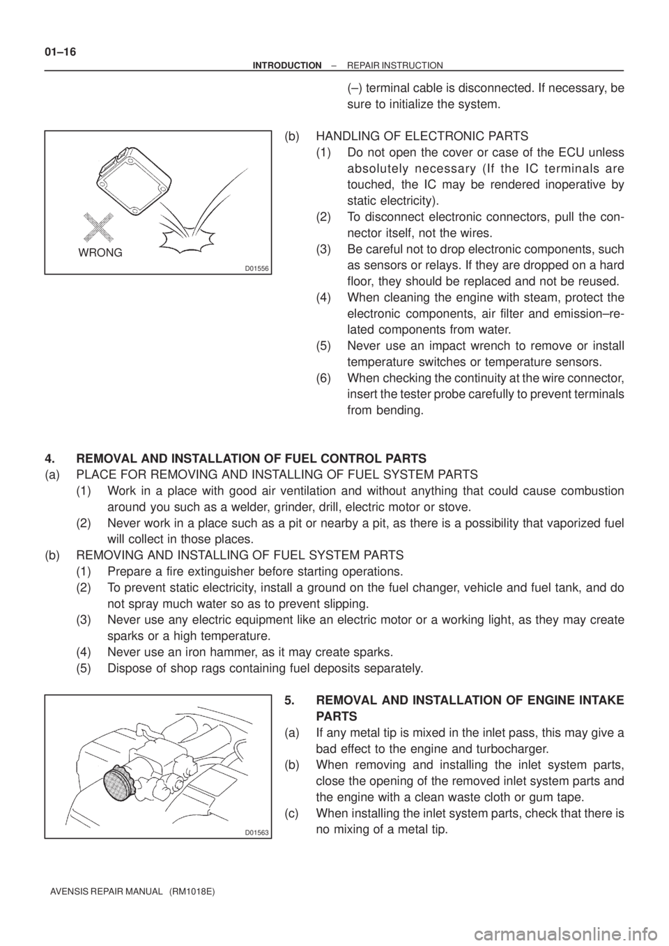
(b) HANDLING OF ELECTRONIC PARTS
(1) Do not open the cover or case of the ECU unless
absolutely necessary (If the IC terminals are
touched, the IC may be rendered inoperative by
static electricity).
(2) To disconnect electronic connectors, pull the con-
nector itself, not the wires.
(3) Be careful not to drop electronic components, such
as sensors or relays. If they are dropped on a hard
floor, they should be replaced and not be reused.
(4) When cleaning the engine with steam, protect the
electronic components, air filter and emission±re-
lated components from water.
(5) Never use an impact wrench to remove or install
temperature switches or temperature sensors.
(6) When checking the continuity at the wire connector,
insert the tester probe carefully to prevent terminals
from bending.
4. REMOVAL AND INSTALLATION OF FUEL CONTROL PARTS
(a) PLACE FOR REMOVING AND INSTALLING OF FUEL SYSTEM PARTS
(1) Work in a place with good air ventilation and without anything that could cause combustion
around you such as a welder, grinder, drill, electric motor or stove.
(2) Never work in a place such as a pit or nearby a pit, as there is a possibility that vaporized fuel
will collect in those places.
(b) REMOVING AND INSTALLING OF FUEL SYSTEM PARTS
(1) Prepare a fire extinguisher before starting operations.
(2) To prevent static electricity, install a ground on the fuel changer, vehicle and fuel tank, and do
not spray much water so as to prevent slipping.
(3) Never use any electric equipment like an electric motor or a working light, as they may create
sparks or a high temperature.
(4) Never use an iron hammer, as it may create sparks.
(5) Dispose of shop rags containing fuel deposits separately.
5. REMOVAL AND INSTALLATION OF ENGINE INTAKE
PARTS
(a) If any metal tip is mixed in the inlet pass, this may give a
bad effect to the engine and turbocharger.
(b) When removing and installing the inlet system parts,
close the opening of the removed inlet system parts and
the engine with a clean waste cloth or gum tape.
(c) When installing the inlet system parts, check that there is
no mixing of a metal tip.
Page 1019 of 1690

± INTRODUCTIONTERMS
01±43
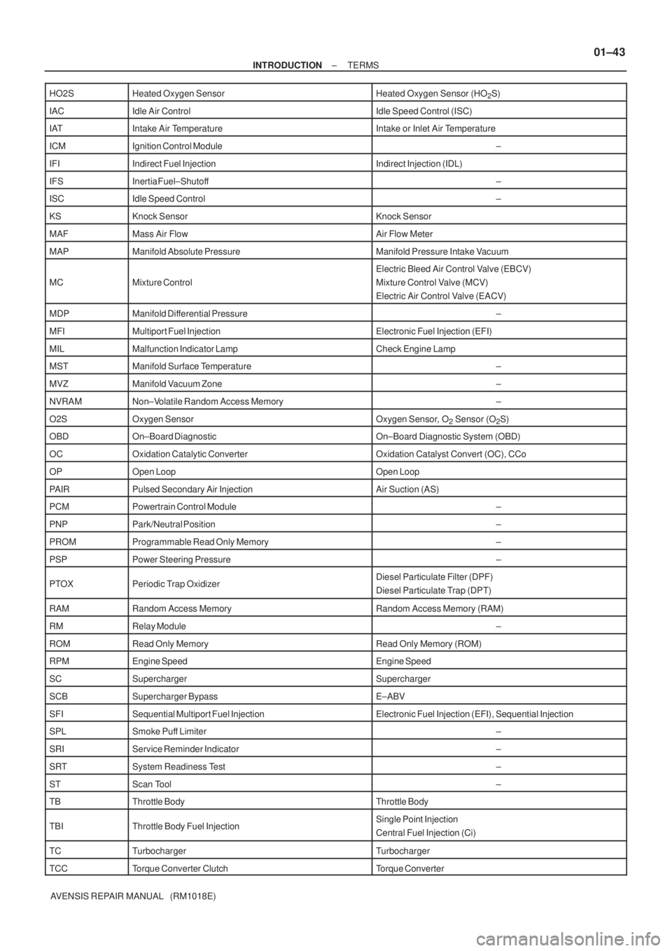
AVENSIS REPAIR MANUAL (RM1018E) HO2S
Heated Oxygen SensorHeated Oxygen Sensor (HO2S)
IACIdle Air ControlIdle Speed Control (ISC)
IATIntake Air TemperatureIntake or Inlet Air Temperature
ICMIgnition Control Module±
IFIIndirect Fuel InjectionIndirect Injection (IDL)
IFSInertia Fuel±Shutoff±
ISCIdle Speed Control±
KSKnock SensorKnock Sensor
MAFMass Air FlowAir Flow Meter
MAPManifold Absolute PressureManifold Pressure Intake Vacuum
MCMixture Control
Electric Bleed Air Control Valve (EBCV)
Mixture Control Valve (MCV)
Electric Air Control Valve (EACV)
MDPManifold Differential Pressure±
MFIMultiport Fuel InjectionElectronic Fuel Injection (EFI)
MILMalfunction Indicator LampCheck Engine Lamp
MSTManifold Surface Temperature±
MVZManifold Vacuum Zone±
NVRAMNon±Volatile Random Access Memory±
O2SOxygen SensorOxygen Sensor, O2 Sensor (O2S)
OBDOn±Board DiagnosticOn±Board Diagnostic System (OBD)
OCOxidation Catalytic ConverterOxidation Catalyst Convert (OC), CCo
OPOpen LoopOpen Loop
PAIRPulsed Secondary Air InjectionAir Suction (AS)
PCMPowertrain Control Module±
PNPPark/Neutral Position±
PROMProgrammable Read Only Memory±
PSPPower Steering Pressure±
PTOXPeriodic Trap OxidizerDiesel Particulate Filter (DPF)
Diesel Particulate Trap (DPT)
RAMRandom Access MemoryRandom Access Memory (RAM)
RMRelay Module±
ROMRead Only MemoryRead Only Memory (ROM)
RPMEngine SpeedEngine Speed
SCSuperchargerSupercharger
SCBSupercharger BypassE±ABV
SFISequential Multiport Fuel InjectionElectronic Fuel Injection (EFI), Sequential Injection
SPLSmoke Puff Limiter±
SRIService Reminder Indicator±
SRTSystem Readiness Test±
STScan Tool±
TBThrottle BodyThrottle Body
TBIThrottle Body Fuel InjectionSingle Point Injection
Central Fuel Injection (Ci)
TCTurbochargerTurbocharger
TCCTorque Converter ClutchTorque Converter