Page 564 of 1690
A76702
Accelerator Control Cable Assy
Heater Inlet Water Hose
Fuel Pipe Clamp
Fuel Tube Sub±assy
Heater Outlet Water Hose
Air Cleaner Cap
W/ Hose
Air Cleaner Filter
Element Sub±assy
Air Cleaner Case Sub±assy Battery Clamp
Sub±assy
Battery
Battery Tray
Battery Carrier
12.8 (131, 9)
N´m (kgf´cm, ft´lbf)
: Specified torque
Union to Connector Tube Hose
Air Cleaner Clamp
Bracket
5.0 (51, 44 in.�lbf)
Fuel Vapor Feed Hose No.1
Fuel Vapor Feed Hose No.3
5.0 (51, 44 in.�lbf)
Oil Cooler
Inlet Hose
Oil Cooler
Outlet Hose
X4
VSV Connector
Mass Air Flow
Meter Connector
14±20
± ENGINE MECHANICALPARTIAL ENGINE ASSY (1ZZ±FE/3ZZ±FE)
AVENSIS REPAIR MANUAL (RM1018E)
Page 728 of 1690

110UD±01
A79188
A80091SST
A79190
11±82
± FUELFUEL FILTER ASSY (1CD±FTV)
AVENSIS REPAIR MANUAL (RM1018E)
FUEL FILTER ASSY (1CD±FTV)
REPLACEMENT
1. REMOVE AIR CLEANER ASSY
(a) Disconnect the connector.
(b) Remove the air cleaner cap with the air cleaner hose.
(c) Remove the air cleaner filter element.
(d) Remove the 3 bolts and the air cleaner case.
2. REMOVE FUEL FILTER ASSY
(a) Disconnect the 2 fuel hose from the fuel filter. (STD or COLD)
(b) Disconnect the 3 fuel hose from the fuel filter. (W/ ADDTIONAL HEATER)
(c) Disconnect the 2 connectors.
(d) Remove the 2 bolts and the fuel filter.
3. DRAIN FUEL
(a) Loosen the drain plug, and drain the fuel from the fuel filter.
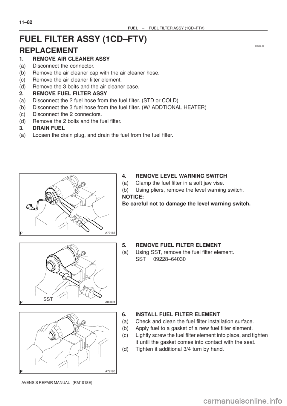
4. REMOVE LEVEL WARNING SWITCH
(a) Clamp the fuel filter in a soft jaw vise.
(b) Using pliers, remove the level warning switch.
NOTICE:
Be careful not to damage the level warning switch.
5. REMOVE FUEL FILTER ELEMENT
(a) Using SST, remove the fuel filter element.
SST 09228±64030
6. INSTALL FUEL FILTER ELEMENT
(a) Check and clean the fuel filter installation surface.
(b) Apply fuel to a gasket of a new fuel filter element.
(c) Lightly screw the fuel filter element into place, and tighten
it until the gasket comes into contact with the seat.
(d) Tighten it additional 3/4 turn by hand.
Page 729 of 1690
±
FUEL FUEL FILTER ASSY(1CD±FTV)
11±83
AVENSIS REPAIR MANUAL (RM1018E)
7.INSTALL LEVEL WARNING SWITCH
(a)Install a new O±ring to the level warning switch.
(b)Apply fuel to the O±ring of the level warning switch.
(c)Install the level warning switch to the fuel filter by hand.
8.INSTALL FUEL FILTER ASSY
Torque: 18 N �m (178 kgf �cm, 13 ft �lbf)
9.INSTALL AIR CLEANER ASSY
Torque: 7.0 N �m (71 kgf �cm, 62 in. �lbf)
10.CHECK FOR FUEL LEAKS(See page 11±60)
Page 761 of 1690

No.1 Fuel Pipe
Fuel Tube Connector
SST
(Clip)
SST (T joint)SST
SST
(Hose)
B12975
11±20
± FUELFUEL SYSTEM (1AZ±FE)
AVENSIS REPAIR MANUAL (RM1018E)
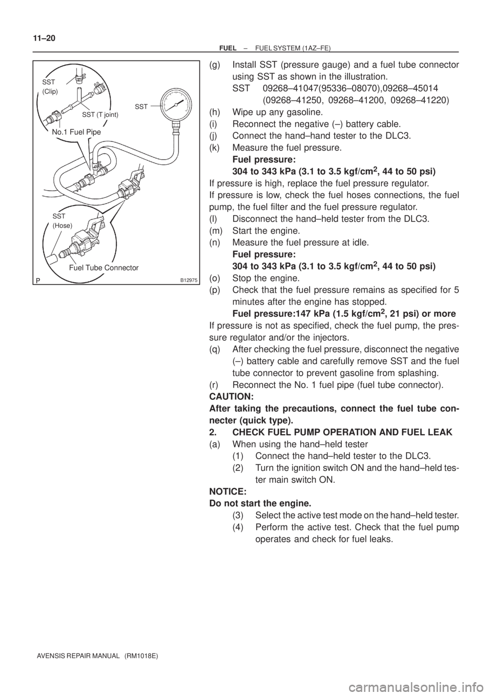
(g) Install SST (pressure gauge) and a fuel tube connector
using SST as shown in the illustration.
SST 09268±41047(95336±08070),09268±45014
(09268±41250, 09268±41200, 09268±41220)
(h) Wipe up any gasoline.
(i) Reconnect the negative (±) battery cable.
(j) Connect the hand±hand tester to the DLC3.
(k) Measure the fuel pressure.
Fuel pressure:
304 to 343 kPa (3.1 to 3.5 kgf/cm
2, 44 to 50 psi)
If pressure is high, replace the fuel pressure regulator.
If pressure is low, check the fuel hoses connections, the fuel
pump, the fuel filter and the fuel pressure regulator.
(l) Disconnect the hand±held tester from the DLC3.
(m) Start the engine.
(n) Measure the fuel pressure at idle.
Fuel pressure:
304 to 343 kPa (3.1 to 3.5 kgf/cm
2, 44 to 50 psi)
(o) Stop the engine.
(p) Check that the fuel pressure remains as specified for 5
minutes after the engine has stopped.
Fuel pressure:147 kPa (1.5 kgf/cm
2, 21 psi) or more
If pressure is not as specified, check the fuel pump, the pres-
sure regulator and/or the injectors.
(q) After checking the fuel pressure, disconnect the negative
(±) battery cable and carefully remove SST and the fuel
tube connector to prevent gasoline from splashing.
(r) Reconnect the No. 1 fuel pipe (fuel tube connector).
CAUTION:
After taking the precautions, connect the fuel tube con-
necter (quick type).
2. CHECK FUEL PUMP OPERATION AND FUEL LEAK
(a) When using the hand±held tester
(1) Connect the hand±held tester to the DLC3.
(2) Turn the ignition switch ON and the hand±held tes-
ter main switch ON.
NOTICE:
Do not start the engine.
(3) Select the active test mode on the hand±held tester.
(4) Perform the active test. Check that the fuel pump
operates and check for fuel leaks.
Page 772 of 1690

No.1 Fuel Pipe
Fuel Tube Connector
SST
(Clip)
SST (T joint)SST
SST
(Hose)
B12975
11±6
± FUELFUEL SYSTEM (1ZZ±FE/3ZZ±FE)
AVENSIS REPAIR MANUAL (RM1018E)
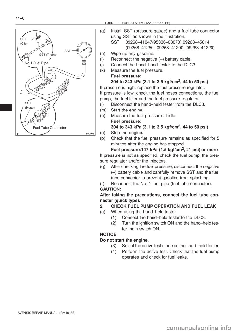
(g) Install SST (pressure gauge) and a fuel tube connector
using SST as shown in the illustration.
SST 09268±41047(95336±08070),09268±45014
(09268±41250, 09268±41200, 09268±41220)
(h) Wipe up any gasoline.
(i) Reconnect the negative (±) battery cable.
(j) Connect the hand±hand tester to the DLC3.
(k) Measure the fuel pressure.
Fuel pressure:
304 to 343 kPa (3.1 to 3.5 kgf/cm
2, 44 to 50 psi)
If pressure is high, replace the fuel pressure regulator.
If pressure is low, check the fuel hoses connections, the fuel
pump, the fuel filter and the fuel pressure regulator.
(l) Disconnect the hand±held tester from the DLC3.
(m) Start the engine.
(n) Measure the fuel pressure at idle.
Fuel pressure:
304 to 343 kPa (3.1 to 3.5 kgf/cm
2, 44 to 50 psi)
(o) Stop the engine.
(p) Check that the fuel pressure remains as specified for 5
minutes after the engine has stopped.
Fuel pressure:147 kPa (1.5 kgf/cm
2, 21 psi) or more
If pressure is not as specified, check the fuel pump, the pres-
sure regulator and/or the injectors.
(q) After checking the fuel pressure, disconnect the negative
(±) battery cable and carefully remove SST and the fuel
tube connector to prevent gasoline from splashing.
(r) Reconnect the No. 1 fuel pipe (fuel tube connector).
CAUTION:
After taking the precautions, connect the fuel tube con-
necter (quick type).
2. CHECK FUEL PUMP OPERATION AND FUEL LEAK
(a) When using the hand±held tester
(1) Connect the hand±held tester to the DLC3.
(2) Turn the ignition switch ON and the hand±held tes-
ter main switch ON.
NOTICE:
Do not start the engine.
(3) Select the active test mode on the hand±held tester.
(4) Perform the active test. Check that the fuel pump
operates and check for fuel leaks.
Page 780 of 1690

No.1 Fuel Pipe
Fuel Tube Connector
SST
(Clip)
SST (T joint)SST
SST
(Hose)
B12975
11±34
± FUELFUEL SYSTEM (1AZ±FSE)
AVENSIS REPAIR MANUAL (RM1018E)
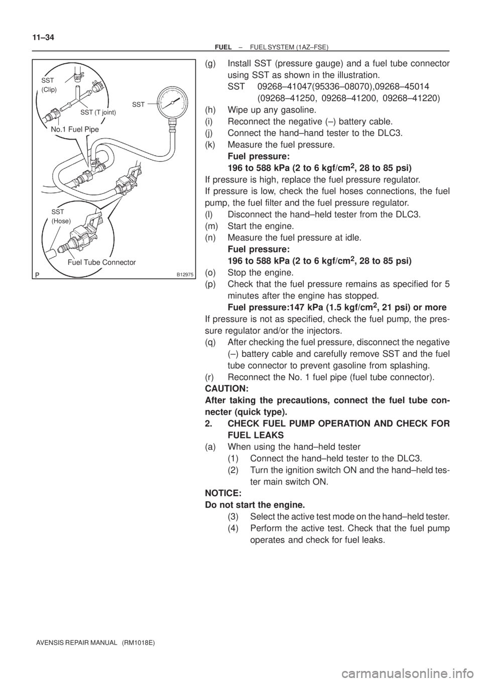
(g) Install SST (pressure gauge) and a fuel tube connector
using SST as shown in the illustration.
SST 09268±41047(95336±08070),09268±45014
(09268±41250, 09268±41200, 09268±41220)
(h) Wipe up any gasoline.
(i) Reconnect the negative (±) battery cable.
(j) Connect the hand±hand tester to the DLC3.
(k) Measure the fuel pressure.
Fuel pressure:
196 to 588 kPa (2 to 6 kgf/cm
2, 28 to 85 psi)
If pressure is high, replace the fuel pressure regulator.
If pressure is low, check the fuel hoses connections, the fuel
pump, the fuel filter and the fuel pressure regulator.
(l) Disconnect the hand±held tester from the DLC3.
(m) Start the engine.
(n) Measure the fuel pressure at idle.
Fuel pressure:
196 to 588 kPa (2 to 6 kgf/cm
2, 28 to 85 psi)
(o) Stop the engine.
(p) Check that the fuel pressure remains as specified for 5
minutes after the engine has stopped.
Fuel pressure:147 kPa (1.5 kgf/cm
2, 21 psi) or more
If pressure is not as specified, check the fuel pump, the pres-
sure regulator and/or the injectors.
(q) After checking the fuel pressure, disconnect the negative
(±) battery cable and carefully remove SST and the fuel
tube connector to prevent gasoline from splashing.
(r) Reconnect the No. 1 fuel pipe (fuel tube connector).
CAUTION:
After taking the precautions, connect the fuel tube con-
necter (quick type).
2. CHECK FUEL PUMP OPERATION AND CHECK FOR
FUEL LEAKS
(a) When using the hand±held tester
(1) Connect the hand±held tester to the DLC3.
(2) Turn the ignition switch ON and the hand±held tes-
ter main switch ON.
NOTICE:
Do not start the engine.
(3) Select the active test mode on the hand±held tester.
(4) Perform the active test. Check that the fuel pump
operates and check for fuel leaks.
Page 809 of 1690
A79436
5.0 (51, 44 in.�lbf)
* 42 (428, 31)
46 (469, 34)
* 31 (316, 23)
34 (347, 25)
* 31 (316, 23)
34 (347, 25)
Injection Pipe Clamp No. 2
Injection Pipe Sub±assy
� Fuel Inlet Pipe Sub±assy
64 (650, 47)
Injection Pump
Drive Pulley
� O±ring Oil Level Gage Guide
: Specified torqueN´m (kgf´cm, ft´lbf)
* Use SST
18 (184, 13)
Oil Level Gage Sub±assy Injection or
Supply Pump Assy
21 (210, 15)
21 (210, 15)
Water Inlet
8.8 (90, 78 in.�lbf)
� Gasket
5.0 (51, 44 in.�lbf)
Intake Manifold
Insulator No. 1
* 42 (428, 31)
46 (469, 34)
Injection Pump to Fuel Filter
Fuel Hose or Pipe
Injection Pump to Fuel Pipe
Fuel Hose
11±68
± FUELINJECTION OR SUPPLY PUMP ASSY (1CD±FTV)
AVENSIS REPAIR MANUAL (RM1018E)
Page 812 of 1690
A79150
A79151
A79152
A62166
SST
±
FUEL INJECTION OR SUPPLY PUMP ASSY(1CD±FTV)
11±71
AVENSIS REPAIR MANUAL (RM1018E)
29.REMOVE INTAKE MANIFOLD INSULATOR NO.1
(a)Remove the 2 bolts and the intake manifold insulator.
30.REMOVE OIL LEVEL GAGE SUB±ASSY
31.REMOVE OIL LEVEL GAGE GUIDE(See page 17±22)
32.REMOVE WATER INLET(See page 16±50) 33. DISCONNECT INJECTION PUMP TO FUEL PIPE FUELHOSE
(a) Disconnect the injection pump to fuel pipe fuel hose from the supply pump.
34. DISCONNECT INJECTION PUMP TO FUEL FILTER FUEL HOSE OR PIPE
(a) Disconnect the injection pump to fuel filter fuel hose or pipe from the supply pump.
35. REMOVE INJECTION PUMP DRIVE PULLEY
(a) Using SST, remove the pulley nut. SST 09960±10010 (09962±01000, 09963±01000)