Page 107 of 1690

4200D±04
D30053
LHD Steering Position Type:
Pedal Height Adjust Point
Push Rod
Play and
Free Play
Adjust
PointPush Rod
Play
Pedal Height
RHD Steering Position Type:
Push Rod Play and
Free Play Adjust Point
Pedal Height
Adjust Point
Push Rod
Play
Pedal Height
42±2
± CLUTCHCLUTCH PEDAL SUB±ASSY (MTM)
AVENSIS REPAIR MANUAL (RM1018E)
CLUTCH PEDAL SUB±ASSY (MTM)
ADJUSTMENT
1. INSPECT AND ADJUST CLUTCH PEDAL SUB±ASSY
(a) Turn over the floor carpet.
(b) Check that the pedal height is correct.
Pedal height from asphalt sheet:
LHD Steering Position Type:
1CD±FTV Engine Type
154.0 to 164.0 mm (6.063 to 6.457 in.)
Others:
139.6 to 149.6 mm (5.496 to 5.890 in.)
RHD Steering Position Type:
1CD±FTV Engine Type
158.4 to 168.4 mm (6.236 to 6.630 in.)
Others:
148.4 to 158.4 mm (5.843 to 6.236 in.)
(c) Adjust the pedal height.
(1) Loosen the lock nut and turn the stopper bolt until
the height is correct. Tighten the lock nut.
Torque: 25 N�m (250 kgf�cm, 18 ft�lbf)
(d) Check that the pedal free play and push rod play are cor-
rect.
(1) Depress the pedal until clutch resistance is felt.
Pedal free play: 5.0 to 15.0 mm (0.197 to 0591 in.)
(2) Gently depress the pedal until the resistance begins
to increase a little.
Push rod play at pedal top:
1.0 to 5.0 mm (0.039 to 0.197 in.)
Page 108 of 1690
 or more
Release Point
Full Stroke
End Position
± CLUTCHCLUTCH PEDAL SUB±ASSY (MTM)
42±3
AVENSIS REPAIR MANUAL (RM1018E)
(e) Adjust the pedal free pla")
CL0102Pedal Free Play
CL0512
25 mm (0.98 in.) or more
Release Point
Full Stroke
End Position
± CLUTCHCLUTCH PEDAL SUB±ASSY (MTM)
42±3
AVENSIS REPAIR MANUAL (RM1018E)
(e) Adjust the pedal free play and push rod play.
(1) Loosen the lock nut and turn the push rod until the
free play and push rod play are correct.
(2) Tighten the lock nut.
(3) After adjusting the pedal free play, check the pedal
height.
(4) Connect the air duct and install the lower finish pan-
el.
(f) Check the clutch release point.
(1) Pull the parking brake lever and install wheel stop-
per.
(2) Start the engine and idle.
(3) Without depressing the clutch pedal, slowly adjust
the shift lever to the reverse position until the gears
contact.
(4) Gradually depress the clutch pedal and measure
the stroke distance from the point that the gear
noise stops (release point) up to the full stroke end
position.
Standard distance: 25 mm (0.98 in.) or more
(From pedal stroke end position to release point)
If the distance is not as specified, perform the following opera-
tions.
�Check pedal height.
�Check push rod play and pedal free play.
�Bleed the clutch line.
�Check the clutch cover assy and disc assy.
Page 109 of 1690
4202T±02
D30054
LHD Steering Position Type:
w/o Turn Over:
Clutch Master Cylinder
Push Rod Clevis w/ Hole Pin
Clutch Pedal Bush
Clutch Master
Cylinder Push Rod
Clevis Bush
Clutch Pedal
Pad Clutch Pedal Bush
Clutch Pedal Sub±assy Clutch Pedal Support Sub±assyClip
19 (195, 14)
37 (375, 27)
12 (120, 9)
w/ Turn Over:
Turn Over Spring
Seat Compression Spring
MP Grease
N�m (kgf�cm, ft�lbf) : Specified torqueClutch Pedal Turn Over Bush
Clutch Pedal No.1 Cushion
19 (195, 14)
Clutch Master Cylinder
Push Rod Clevis w/ Hole PinClip
37 (375, 27)
Clutch Pedal Support Sub±assy12 (120, 9)
� Clutch Pedal Bush
Clutch Pedal Sub±assy
Clutch Master
Cylinder Push Rod
Clevis Bush
�
Clutch Pedal
Pad
Clutch Pedal No.1 Cushion
�Non±reusable partBush Clutch Pedal
Clutch Pedal Spring 1CD±FTV Engine Type:
Clutch Pedal Spring
Clutch Start Switch Assy
16 (160, 12)
Clutch Pedal Turn Over Bush
42±4
± CLUTCHCLUTCH PEDAL SUB±ASSY (MTM)
AVENSIS REPAIR MANUAL (RM1018E)
COMPONENTS
Page 110 of 1690

D30304
RHD Power Steering Type:
w/o Turn Over:
Clutch Master Cylinder
Push Rod Clevis w/ Hole Pin
Clutch Pedal SpringClutch Pedal Bush
Clutch Master
Cylinder Push Rod
Clevis Bush
Clutch Pedal
Pad Clutch Pedal Bush
Clutch Pedal Sub±assy Clip
19 (195, 14)
37 (375, 27)
12 (120, 9)
Clutch Pedal No.1 Cushion
w/ Turn Over:
MP Grease
N�m (kgf�cm, ft�lbf) : Specified torque
Clutch Master Cylinder
Push Rod Clevis w/ Hole Pin
Clip
37 (375, 27)
Turn Over Spring
Seat Compression Spring
Clutch Pedal Support Sub±assy
Clutch Master
Cylinder Push Rod
Clevis Bush
Clutch Pedal No.1 Cushion
Clutch Pedal
Pad Clutch Pedal No.1 CushionClutch Pedal Sub±assyClutch Pedal
Turn Over Bush
19 (195, 14)
�Non±reusable part� Clutch Pedal Bush� Clutch Pedal Bush Clutch Pedal Support Sub±assy
1CD±FTV Engine Type:
Clutch Pedal Spring
19 (195, 14)
Clutch Pedal Turn Over Bush
19 (195, 14)Clutch Start Switch Assy
12 (120, 9)
Clutch Pedal No.1 Cushion
16 (160, 12)
± CLUTCHCLUTCH PEDAL SUB±ASSY (MTM)
42±5
AVENSIS REPAIR MANUAL (RM1018E)
Page 117 of 1690
4202X±03
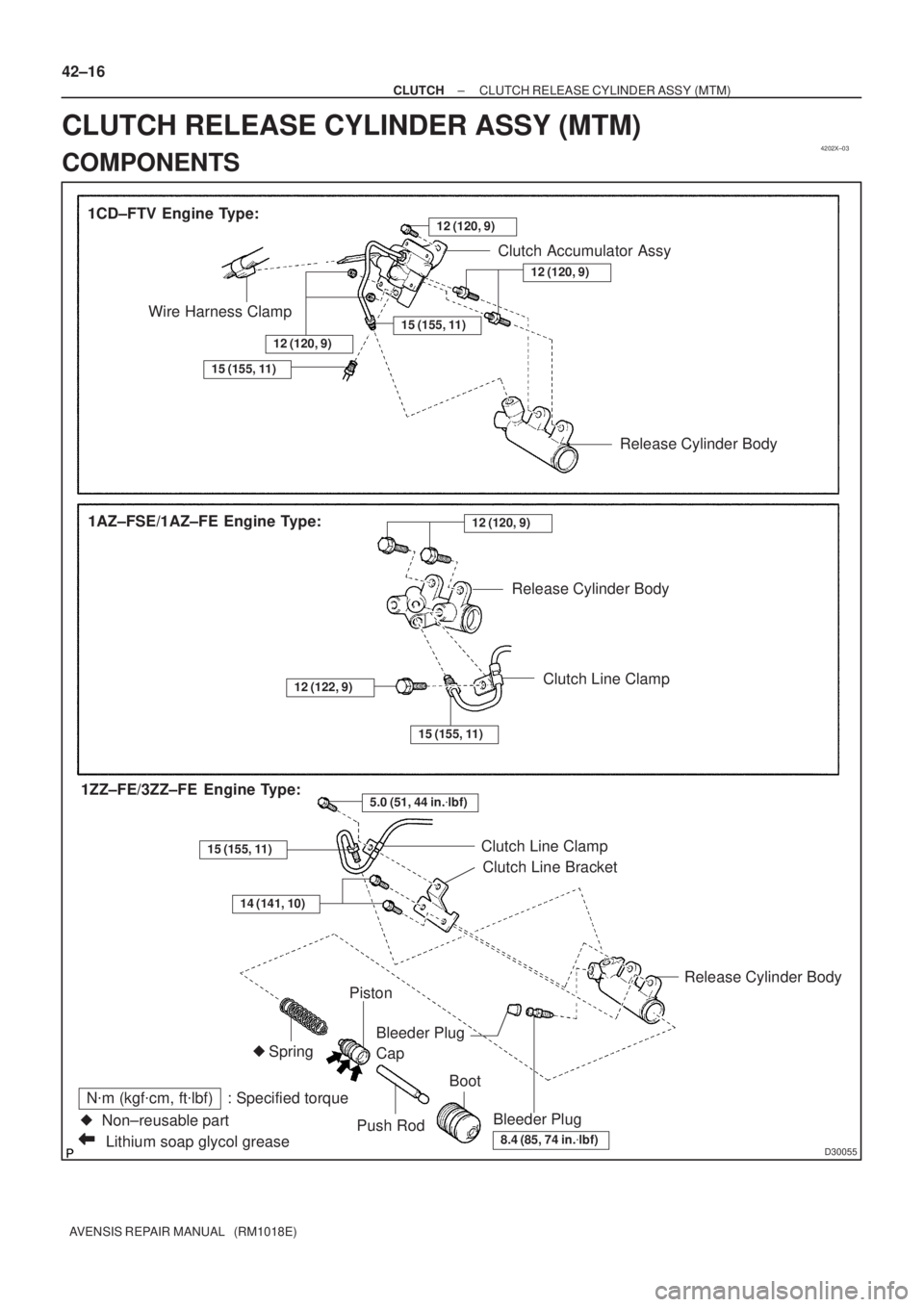
D30055Lithium soap glycol grease
N�m (kgf�cm, ft�lbf) : Specified torque
�Non±reusable part 1CD±FTV Engine Type:
Bleeder PlugRelease Cylinder Body
Piston
Push RodBoot Bleeder Plug
Cap
8.4 (85, 74 in.�lbf)
Wire Harness ClampClutch Accumulator Assy
Spring
1AZ±FSE/1AZ±FE Engine Type:
15 (155, 11)
12 (120, 9)
�
12 (120, 9)
Release Cylinder Body
12 (120, 9)
Release Cylinder Body
Clutch Line Clamp
Clutch Line Bracket
15 (155, 11)
12 (122, 9)
5.0 (51, 44 in.�lbf)1ZZ±FE/3ZZ±FE Engine Type:
15 (155, 11)Clutch Line Clamp
14 (141, 10)
15 (155, 11)
12 (120, 9)
42±16
± CLUTCHCLUTCH RELEASE CYLINDER ASSY (MTM)
AVENSIS REPAIR MANUAL (RM1018E)
CLUTCH RELEASE CYLINDER ASSY (MTM)
COMPONENTS
Page 118 of 1690
4206F±01
D30487
SST(s)
1ZZ±FE/3ZZ±FE Engine Type:
1AZ±FE/1AZ±FSE Engine Type:SST(s)
D30814
±
CLUTCH CLUTCH RELEASE CYLINDER ASSY (MTM)
42±17
AVENSIS REPAIR MANUAL (RM1018E)
OVERHAUL
1. REMOVE BATTERY (1CD±FTV ENGINE TYPE)
2.REMOVE AIR TUBE NO.1 (1CD±FTV ENGINE TYPE) (See page 14±286)
3. DISCONNECT CLUTCH RELEASE CYLINDER TOFLEXIBLE HOSE TUBE (EXCEPT 1CD±FTV ENGINE
TYPE)
(a) Using SST(s), disconnect the flexible hose tube. SST 09023±00100
HINT:
Use a container to catch the fluid.
4. REMOVE CLUTCH ACCUMULATOR ASSY (1CD±FTV ENGINE TYPE)
(a) Disconnect the wire harness clamp.
(b) Using SST(s), disconnect the 2 flexible hose tubes. SST 09023±00100
HINT:
Use a container to catch the fluid.
(c) Remove the 2 nuts, bolt and clutch accumulator assy.
Page 119 of 1690

AVENSIS REPAIR MANUAL (RM1018E)
5. REMOVE CLUTCH RELEASE CYLINDER ASSY
(")
D30488
1ZZ±FE/3ZZ±FE Engine Type:
1AZ±FE/1AZ±FSE Engine Type:
D26804
42±18
± CLUTCHCLUTCH RELEASE CYLINDER ASSY (MTM)
AVENSIS REPAIR MANUAL (RM1018E)
5. REMOVE CLUTCH RELEASE CYLINDER ASSY
(EXCEPT 1CD±FTV ENGINE TYPE)
(a) 1ZZ±FE/3ZZ±FE Engine Type:
Remove the 3 bolts, clutch release cylinder assy, and
clutch line bracket.
(b) 1AZ±FE/1AZ±FSE Engine Type:
Remove the 3 bolts and clutch release cylinder assy.
6. REMOVE CLUTCH RELEASE CYLINDER ASSY
(1CD±FTV ENGINE TYPE)
(a) Using a 12 mm deep socket wrench, remove the 2 bolts
and clutch release cylinder assy.
7. REMOVE CLUTCH RELEASE CYLINDER KIT
(a) Remove the boot from the cylinder body.
(b) Remove the push rod from the cylinder body.
(c) Remove the piston from the cylinder body.
NOTICE:
Be careful not to damage the inside of the cylinder body.
(d) Remove the spring from the cylinder body.
(e) Remove the bleeder plug cap from the bleeder plug.
8. REMOVE RELEASE CYLINDER BLEEDER PLUG
9. INSTALL RELEASE CYLINDER BLEEDER PLUG
Torque: 8.3 N�m (85 kgf�cm, 73 in.�lbf)
Page 120 of 1690

(1)
(1)
(1)
(2) (2)
± CLUTCHCLUTCH RELEASE CYLINDER ASSY (MTM)
42±19
AVENSIS REPAIR MANUAL (RM1018E)
10. INSTAL")
CL0672
D26804
D30488
1ZZ±FE/3ZZ±FE Engine Type:
1AZ±FE/1AZ±FSE Engine Type:(1)
(1)
(1)
(1)
(2) (2)
± CLUTCHCLUTCH RELEASE CYLINDER ASSY (MTM)
42±19
AVENSIS REPAIR MANUAL (RM1018E)
10. INSTALL CLUTCH RELEASE CYLINDER KIT
(a) Install the bleeder plug cap to the bleeder plug.
(b) Install a new spring to the cylinder body.
(c) Coat the parts with lithium soap base glycol grease, as
shown in the illustration.
(d) Install the piston to the cylinder body.
NOTICE:
Be careful not to damage the inside of the cylinder body.
(e) Install the push rod to the cylinder body.
(f) Install the boot to the cylinder body.
11. INSTALL CLUTCH RELEASE CYLINDER ASSY
(1CD±FTV ENGINE TYPE)
(a) Using a 12 mm deep socket wrench, install the clutch re-
lease cylinder assy with the 2 bolts.
Torque: 12 N�m (120 kgf�cm, 9 ft�lbf)
12. INSTALL CLUTCH RELEASE CYLINDER ASSY
(EXCEPT 1CD±FTV ENGINE TYPE)
(a) 1ZZ±FE/3ZZ±FE Engine Type:
(1) Install the clutch release cylinder and clutch line
bracket with the 2 bolts.
Torque: 14 N�m (141 kgf�cm, 10 ft�lbf)
(2) Install the flexible hose tube with the bolt.
Torque: 5.0 N�m (51 kgf�cm, 44 in.�lbf)
(b) 1AZ±FE/1AZ±FSE Engine Type:
(1) Install the clutch release cylinder with the 2 bolts.
Torque: 12 N�m (120 kgf�cm, 9 ft�lbf)
(2) Install the flexible hose tube with the bolt.
Torque: 12 N�m (122 kgf�cm, 9 ft�lbf)


1ZZ±FE/3ZZ±FE Engine Type:
1AZ±FE/1AZ±FSE Engine Type:SST(s)
D30814
±
CLUTCH CLUTCH RELEASE CYLINDER ASSY (MTM)
42±17
AVENSIS REPAIR MANUAL (RM1018E)
OVERHAUL
1. REMOV")